DATASHEET
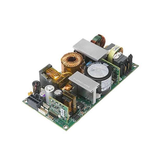
CLP0512 Open Frame Power Supply
90 - 265Vac Input; 12Vdc Output; 550W Output Power; 5V Standby 5V@1A
Description
In a s
l 3 x 6-inch footprint, the 12Vdc
open frame power supply delivers greater than 90
typical power e f f i c i e n c y and 450W capability at 45ºC and 1m/s airflow with derating at higher temperatures
or lower airflows. Protection features include output
overvoltage
and
(OTP).
Applications include: Industrial Equipment | Telecommunications Equipment | Networks, Routers, Switchers
Features
•
Compact size 76.2 mm x 152.4 mm x 35 mm (3 in x 6 in x
1.38 in) with density of 21.8 W/in3
•
Output overvoltage protection
•
•
Universal AC Input Range (90 - 265VAC )
Minimum of 11ms of holdup time at 550W out
•
•
Output voltage of 12V (adjustable ±5%)
Parallelable with output current sharing
•
•
Standby output of 5V @ 1A
Active power factor corrected input
•
•
Maximum output current of 45.8A @ 12Vout (550W)
Conducted EMI - meets CISPR22 (EN55022) and FCC Class
B requirements
•
High efficiency (>90% at Full Load, 230VAC in )
•
•
550W capability at 115 VIN, 50
ambient, 400lfm airflow
with derating at higher temperatures or lower airflows
Meets IEC61000-4-5, Level 4 (2kV/4kV) and ANSI C62.41
(6kV)
•
Compliant to RoHS II EU Directive 2011/65/EU
•
420W output at 90 VIN for sealed enclosure applications,
with enclosure outside surface temp at 55
and
enclosure inside ambient at 85
•
UL and cUL approved to UL/CSA60950-1, TUV
(EN60950-1), CE Mark (for LVD) and CB Report available
•
Output overcurrent protection (non-latching)
•
ISO** 9001 and ISO 14001 certified manufacturing facilities
•
Overtemperature protection
•
AC OK signal
•
Dual input fusing option - Line & Return
See footnotes on page 4
Page 1
© 2020 ABB. All rights reserved.
�Technical Specifications
Absolute Maximum Ratings
Stresses over the absolute maximum ratings can cause permanent damage to the device. These are absolute stress ratings
only. Functional operation of the device is not implied at these or any other conditions over those given in the operations
sections of the data sheet. Exposure to absolute maximum ratings for extended periods can adversely affect the device
reliability.
Parameter
Device
Min
Max
Unit
All
90
265
Vac
All
90
275
Vac
All
-40
85
°C
Storage Temperature
All
-40
85
°C
Humidity (non-condensing)
All
5
95
%
Altitude
All
5000
m
Isolation Voltage—Input to output
All
3000
Vac
Input to safety ground
All
1500
Vac
Outputs to safety ground
All
50
Vac
Input Voltage - Continuous Operation
For up to 10 seconds operation
Operating Ambient Temperature
(see Thermal Considerations section)
Electrical Specifications
Parameter
Device
Min
Typ
Max
Unit
Operating Input Voltage
Input Source Frequency
Input Current (VIN = 90Vac)
Input Power Factor (230Vac, Full Load)
Inrush Transient Current (VIN = 265Vac, Tamb = 25ºC)
Leakage Current to earth ground (VIN = 265Vac)
Output Voltage Setpoint
Output Voltage Tolerance (due to set point, temperature variations, load
All
All
All
All
All
All
All
90
47
115/230
50/60
6.8
265
63
Vac
Hz
ARMS
0.95
60
3.5
A Peak
mA
Vdc
All
-2
2
%
Output Voltage Adjustment Range
Output Remote Sense Range
All
All
11.4
12.6
250
Vdc
mVdc
Output Load Regulation
All
1
%Vout
Output Line Regulation
All
0.5
%Vout
Output Ripple and Noise – measured with 0.1µF ceramic capacitor
and 10µF electrolytic capacitor in parallel Peak-to-peak (20MHz
All
180
mV p-p
Dynamic Load Response – 50% to 100% load transient,
1A/µs slew rate
Output voltage deviation
and line regulation)
12
Bandwidth; output ripple specification is met over 0to 85 oC)
All
5%
%
Settling Time
All
500
µs
Output Current
All
0
45.8
Adc
Output Current Limit Inception
Maximum Output Capacitance
All
All
110
145
10000
% IO,max
µF
Standby Output Voltage
Standby Output Current
All except
All except
-continued on next page-
See footnotes on page 4
Page 2
© 2020 ABB. All rights reserved.
5
Vdc
1
Adc
�Technical Specifications (continued)
Electrical Specifications con’t.
Parameter
Device
Min
Typ
Max
Unit
Efficiency VIN = 230Vac—20% load
50% load
100% load
All
All
All
87
92
92.7
%
%
%
Efficiency: VIN = 115Vac— 20% load
All
86
%
50% load
100% load
Holdup Time2 — VIN = 115Vac, 550W load
VIN = 230Vac, 450W load
All
All
All
All
91
91
%
%
ms
ms
11
11
General Specifications
Parameter
Device
Symbol
Typ
Unit
All
MTBF
>750,000
Hours
463
16.3
g
oz.
Calculated Reliability based on Telcordia SR-332 Issue 2:
Method 1 Case 3 (VIN=230Vac, 80% full load, TA = 40ºC, airflow
200LFM, 90% confidence)
Weight
All
Feature Specifications
Parameter
Device
Min
Typ
Max
Unit
All except
0.2
mA
All except
0.5
V
1.1
5.5
50
µA
V
ms
On/Off Signal Interface – signal referenced to GND
Logic Low (Power Supply ON)
Input Low Current
Input Low Voltage
Logic High (Power Supply OFF)
Input High Current
Input Voltage
Delay from ON/OFF being enabled to start of output voltage rise
All except
All except
All except
Output Voltage Rise Time (from 10 to 90% of final value)
All
Delay from Input being applied to all outputs being in regulation
All
Output Overvoltage Protection
All
2.5
20
13.8
ms
800
Ms
16
Vdc
Input Undervoltage lockout2
Turn-on Threshold (100% load)
All
86
Vac
Turn-off Threshold (100% load)
All
81
Vac
DC OK – open collector, High when output available
Sink Current
All except
4
mA
Maximum Collector Voltage
All except
12
V
Sink Current
All except
4
mA
Maximum Collector Voltage
All except
12
V
AC OK – open collector, High when output available
See footnotes on page 4
Page 3
© 2020 ABB. All rights reserved.
�Technical Specifications (continued)
Safety Specifications
Parameter
Device
Specification
Dielectric Withstand Voltage (between input and output)
All
Minimum of 4,250Vdc for 1 minute
Insulation Resistance (between input and output)
All
Minimum of 5 MΩ
All
Class 1, IEC60950, EN60950, with the following
deviations: Nemko, UL 60950 (Recognized Component), cUL (Canadian Approval by UL)
Safety Standards
Environmental Specifications
Parameter
Device
Specification
Radiated Emissions3
Conducted Emissions
ESD
Radiated Susceptibility4
All
All
All
All
CISPR22 Class B with 3dB margin
CISPR22 Class B with 6dB margin
IEC 61000-4-2, Level 3
IEC 61000-4-3, Level 3
Electrical Fast Transient Common Mode
All
IEC 61000-4-4, Level 3
may be observed during an event > 5% for 20 us
application dependent)
All
IEC 61000-4-5, Level 4
Conducted RF Immunity
All
Input Voltage Dips
All
Input Harmonics
All
IEC 61000-4-6, Level 3
Output stays within regulation for either ½ cycle interruption or 25% dip from
nominal line for 1 second
IEC61000-3-2
Shock and Vibration
All
Per IPC-9592B, Class II
Surge Immunity (note-overshoot or undershoot
Footnotes
*UL is a registered trademark of Underwriters Laboratories, Inc.
†
CSA is a registered trademark of Canadian Standards Association.
‡
VDE is a registered trademark of Verband Deutscher Elektrotechniker e..V.
** ISO is a registered trademark of the International Organization of Standard
1
Holdup time may be lower at cold temperatures
2
Undervoltage lockout threshold may vary with output load current level – decreasing as load goes lower
3
Shall meet when tested in a suitable enclosure
4
Shall meet when tested in a suitable enclosure
Page 4
© 2020 ABB. All rights reserved.
�Technical Specifications (continued)
Characteristic Curves (CLP0512)
The following figures provide typical characteristics for the CLP0512 power supply.
OUTPUT VOLTAGE
VO (V) (200mV/div)
IO (20A)/(div)
OUTPUT VOLTAGE
Vo (V) (200mV/div)
Vpk-pk:67mV
OUTPUT CURRENT
Figure 1: Power Supply Efficiency Versus Output Current
TIME, t (10µs/div)
TIME, t (20µs/div)
Figure 2. Typical output ripple and noise (VIN = 230Vac, 100% load )
Figure 3. Transient Response to Dynamic Load Change from
50% to 100% at VIN = 230Vac
Page 5
© 2020 ABB. All rights reserved.
�Technical Specifications (continu
Characteristic Curves con’t. (CLP0512)
INPUT VOLTAGE (Red)
VIN (V) (200V/div)
INPUT VOLTAGE (Red)
VIN (V) (200V/div)
OUTPUT VOLTAGE
Vo (V) (10v/div)
OUTPUT VOLTAGE
Vo (V) (10V/div)
The following figures provide typical characteristics for the CLP0512 power supply.
TIME, t (50µs/div)
Figure 4. Typical Start-up (VIN = 90Vac, Full Load)
Figure 5. Typical Start-up (VIN = 230V, Full Load)
Hold up time: 14.1mS
INPUT VOLTAGE (Red)
VIN (V) (200V/div)
INPUT VOLTAGE (Red)
VIN (V) (100V/div)
OUTPUT VOLTAGE
Vo (V) (10/div)
Hold up time: 14.1mS
OUTPUT VOLTAGE
Vo (V) (2V/div)
TIME, t (10µs/div)
TIME, t (10µs/div)
TIME, t (10µs/div)
Figure 6. Typical Hold-up Waveforms (VIN = 115Vac, 100% Load)
Figure 7. Typical Hold-up Waveforms (VIN = 230V, 100% Load)
Page 6
© 2020 ABB. All rights reserved.
�Technical Specifications (continued)
Power Derating for Forced Air Flow Application (CLP0512)
Air flow direction: Long Side (refer to Figure 2: Preferred Airflow Direction for Cooling
Power Derating for Conduction Cooling (CLP0512)
Enclosure Application; No load inside enclosure
Page 7
© 2020 ABB. All rights reserved.
Enclosure Application; with 420W resistive load inside enclosure
Enclosure Outside
Surface (°C)
Enclosure Inside
Ambient (°C)
Resistive Load ( W )
on CLP0512
55
85
420
�Technical Specifications (continued)
Safety Considerations
The
supply operates normally once the output current is brought back
into its specified range.
power supply is intended for inclusion in other
and the installer must ensure that it is complied
with all
of the end application.
product
is only for inclusion by professional installers within other
and must
be
The power supply
as a
Component)
Overvoltage protection is a feature of the CLP0512 power
supply that protects both the load and the power supply from
an output overvoltage condition. When an overvoltage occurs,
meet Class 1,
with the
Overvoltage Protection
60950
(Canadian Approval by
Feature Descriptions
Standby Power Supply
A standby output of 5V in the CLP0512 power supply comes on
when AC input in the operating range is applied. 5V standby
power is not isolated with main output.
Remote On/Off
The CLP0512 power supply features a TTL-compatible On/Off
control input. The power supply turns ON when the On/Off
input goes low, and turns OFF when the input goes high. Note
that if the On/Off pin is left unconnected, the power supply
main output will turn ON when AC input is present.
the power supply shuts down and latches off until the
overvoltage condition is removed. It is necessary to recycle
the input to restart the power supply when this protection
is activated.
Overtemperature Protection
The CLP0512 also features overtemperature protection in order
to provide additional protection in a fault condition. The power
supply is equipped with a thermal shutdown circuit which detects
excessive internal temperatures and shuts the unit down. Once
the power supply goes into overtemperature shutdown, it will
cool before attempting to restart. The overtemperature
protection circuit will typically kick in when the unit is operated at
550W output with an ambient temperature of 49ºC and 1m/s
(200LFM) airflow and 115Vac.
Input Undervoltage Lockout
At input voltages below the input under-voltage lockout limit,
power supply operation is disabled. The power supply will begin
to operate at an input voltage above the under-voltage lockout
turn-on threshold.
DC OK
The CLP0512 provides a DC OK signal that indicates when
the output has come up and is in regulation. This is an
open-collector type signal that goes high when the output
Is available and within regulation.
AC OK
The CLP0512 provides an AC OK signal that indicates when
Output Voltage Adjustment
the Input Vin is in operational range. This is an
open- collector type signal that goes High when the Input
The output voltage can be adjusted between 11.4V and 12.6V using
Vo
a potentiometer on the power supply.
referenced to Vout return.
Remote Sense
Power Good LED
The power supply has both positive and negative remote sense
A green LED on board the power supply illuminates when the main
connections that can be connected to the positive and negative
rails of the main output near the load. The power supply operates
even without the remote sense connections being made.
Overcurrent Protection
To provide protection in a fault condition (output overload), the
power supply is equipped with internal current-limiting circuitry
and can endure current limiting continuously. At the point of
current-limit inception, the unit enters hiccup mode. The power
Page 8
© 2020 ABB. All rights reserved.
s within Range. This signal is isolated from Vin and
output voltage is above 10V.
�Technical Specifications (continued)
Paralleling with Active Output Current Sharing
(option)
conductive pads are used to transfer heat from the top and bottom
The CLP0512 is capable of being employed in a paralleling scheme,
Power Derating Curves/Enclosure Application.
of the power supply into the enclosure. Under such conditions, the
power supply is capable of reduced power operation as shown in
following are some design attributes that need to be carefully
considered prior to attempting a parallel operation with multiple
CLP0512’s. With the following design criteria the CLP0512 will load
share at an accuracy of +/-5%, when the total current draw is at
levels above 20% of max overall loading.
•
Current share signals of each power supply to be connected.
•
An external Oring function needs to be employed at the Vout
(+) signal. An oring diode or a Mosfet & controller scheme can
be used.
•
The 5V Standby Return SHOULD NEVER be connected with
the VOUT-(RETURN ). 5V stby returns will need to be
connected together, the 5V stby Vout(+) leg remain
separate. The 5V stby output is not designed to be
paralleled, if there is a desire for these to be paralleled for
load sharing, then other considerations need to be included
as well. Contact your local ABB sales rep for FAE involvement.
•
In the parallel scheme the remote sense function needs to be
unused and remote sense signals left floating.
Assembling
Please use metal screw to mount the unit and make sure
4 mounting holes connected to Earth well.
In Applications were the power supply is enclosed, special
attention to clearances between the supply and the enclosure
should be a min. 3.5mm on all sides for improved safety. For
additional protection a layer of Kapton tape, 3 mil in thickness
covering the whole surface under the supply is recommend. If a
cover is used a 3 mil Kapton Tape covering the whole cover is also
recommend. Please contact your local ABB FAE if further
Fig. 1. Example arrangement of the CLP0512 for sealed
enclosure applications.
Thermal conductivity should be 3.0 W/m-K for thermal
pad application and 1kV+ isolation, example:
Thermal gap pad:
http://www.bergquistcompany.com/pdfs/dataSheets/
PDS_GP_HC3_0714%20v7.pdf
Thermal gap pad:
https://www.lairdtech.com/products/tputty-502
information is needed.
Thermal Considerations
Heat Transfer Via Convection
The power supply can be operated in a variety of thermal
Increased airflow through the power supply enhances the heat
environments; however sufficient cooling should be provided to
ensure reliable operation.
Considerations include ambient temperature, airflow, power
transfer via convection. Fig 2 shows the preferred airflow
direction. Contact your technical representative for derating
information in other airflow directions.
supply dissipation and the need for increased reliability. A
reduction in the operating temperature of the power supply will
result in increased reliability. The power supply can deliver 550W
capability at 50ºC and 400LFM airflow with derating at higher
temperatures or lower airflows.
Operation in a Sealed Enclosure
The CLP0512 power supply can also be operated in a sealed
enclosure or in an environment where cooling is primarily via
conduction. Figure 10 shows an arrangement where thermally
Page 9
© 2020 ABB. All rights reserved.
Fig. 2. Preferred airflow direction for cooling
�Technical Specifications (continued)
Mechanical Outline (CLP0512)
Page 10
© 2020 ABB. All rights reserved.
�Technical Specifications (continued)
Connector Information
Connector on
Power Supply
Connector Housing
Crimp Terminal
TPA
AC Input Connector
(HDR200)
Molex 41671-3473
Molex 09-50-3031
or equivalent
or equivalent
Molex 08-52-0071
or equivalent
\
DC Output Connector
(HDR600)
Molex 172298-1210
Molex 172258-1110
Molex 172253-3023
Molex 172264-1008
or equivalent
or equivalent
or equivalent
or equivalent
FCI 98414-G04-10ULF
FCI 90311-010LF
or equivalent
or equivalent
Connector
Auxiliary Connector
(HDR801)
FCI 10044403
(22~24AWG)
\
or equivalent
TE 110series
Ground Pin (TERM200)
Receptacles
TE P/N: 63756-1
eg:63093-1 18~14AWG
or equivalent
Pinout Information
AC Input Connector (HDR200)
INT 1
INT 2
L
N
DC Output Connector (HDR600)
Pins 1 - 5
Pins 6-10
12 VOUT
12VRTN
Auxiliary Connector (HDR801)
Pin A1 - SV Standby
Pin A2 - SV Standby
Pin A3 - AC_OK
Pin B1 - ISHARE
Pin B2 - SV Standby Return
Pin B3 - SV Standby Return
Pin A4 - REMOTE SENSE +
Pin B4 - DC_OK
Pin A5 - REMOTE SENSE -
Pin B5 - ON/OFF
Ordering Information
Device
Code
Input
Voltage
Range
Output
Voltage
Output
Current
On/Off
Control
Standby
Supply
Temperature
Range
Comcode
CLP0512FPXX
XZ01A
90-265Vac
12.0Vdc
45.8A
Negative
Logic
5V @ 1A
-40 to 85ºC
CLP0512FPXXXZ01A
Page 11
© 2020 ABB. All rights reserved.
�ABB
601 Shiloh Rd.
Plano, TX USA
Go.ABB/Industrial
We reserve the right to make technical changes or modify the
We reserve all rights in this document and in the subject matter and
contents of this document without prior notice. With regard
illustrations contained therein. Any reproduction, disclosure to third
to purchase orders, the agreed particulars shall prevail.
parties or utilization of its contents – in whole or in parts – is
ABB does not accept any responsibility whatsoever
forbidden without prior written consent of ABB.
for potential errors or possible lack of information in this
document.
Copyright© 2020 ABB
All rights reserved
Page 12
© 2020 ABB. All rights reserved.
�


 工商网监
湘ICP备2023018690号
工商网监
湘ICP备2023018690号
