MCP2200
USB to UART with Isolation
Demo Board
User’s Guide
2015 Microchip Technology Inc.
DS50002352A
�Note the following details of the code protection feature on Microchip devices:
•
Microchip products meet the specification contained in their particular Microchip Data Sheet.
•
Microchip believes that its family of products is one of the most secure families of its kind on the market today, when used in the
intended manner and under normal conditions.
•
There are dishonest and possibly illegal methods used to breach the code protection feature. All of these methods, to our
knowledge, require using the Microchip products in a manner outside the operating specifications contained in Microchip’s Data
Sheets. Most likely, the person doing so is engaged in theft of intellectual property.
•
Microchip is willing to work with the customer who is concerned about the integrity of their code.
•
Neither Microchip nor any other semiconductor manufacturer can guarantee the security of their code. Code protection does not
mean that we are guaranteeing the product as “unbreakable.”
Code protection is constantly evolving. We at Microchip are committed to continuously improving the code protection features of our
products. Attempts to break Microchip’s code protection feature may be a violation of the Digital Millennium Copyright Act. If such acts
allow unauthorized access to your software or other copyrighted work, you may have a right to sue for relief under that Act.
Information contained in this publication regarding device
applications and the like is provided only for your convenience
and may be superseded by updates. It is your responsibility to
ensure that your application meets with your specifications.
MICROCHIP MAKES NO REPRESENTATIONS OR
WARRANTIES OF ANY KIND WHETHER EXPRESS OR
IMPLIED, WRITTEN OR ORAL, STATUTORY OR
OTHERWISE, RELATED TO THE INFORMATION,
INCLUDING BUT NOT LIMITED TO ITS CONDITION,
QUALITY, PERFORMANCE, MERCHANTABILITY OR
FITNESS FOR PURPOSE. Microchip disclaims all liability
arising from this information and its use. Use of Microchip
devices in life support and/or safety applications is entirely at
the buyer’s risk, and the buyer agrees to defend, indemnify and
hold harmless Microchip from any and all damages, claims,
suits, or expenses resulting from such use. No licenses are
conveyed, implicitly or otherwise, under any Microchip
intellectual property rights.
Trademarks
The Microchip name and logo, the Microchip logo, dsPIC,
FlashFlex, flexPWR, JukeBlox, KEELOQ, KEELOQ logo, Kleer,
LANCheck, MediaLB, MOST, MOST logo, MPLAB,
OptoLyzer, PIC, PICSTART, PIC32 logo, RightTouch, SpyNIC,
SST, SST Logo, SuperFlash and UNI/O are registered
trademarks of Microchip Technology Incorporated in the
U.S.A. and other countries.
The Embedded Control Solutions Company and mTouch are
registered trademarks of Microchip Technology Incorporated
in the U.S.A.
Analog-for-the-Digital Age, BodyCom, chipKIT, chipKIT logo,
CodeGuard, dsPICDEM, dsPICDEM.net, ECAN, In-Circuit
Serial Programming, ICSP, Inter-Chip Connectivity, KleerNet,
KleerNet logo, MiWi, MPASM, MPF, MPLAB Certified logo,
MPLIB, MPLINK, MultiTRAK, NetDetach, Omniscient Code
Generation, PICDEM, PICDEM.net, PICkit, PICtail,
RightTouch logo, REAL ICE, SQI, Serial Quad I/O, Total
Endurance, TSHARC, USBCheck, VariSense, ViewSpan,
WiperLock, Wireless DNA, and ZENA are trademarks of
Microchip Technology Incorporated in the U.S.A. and other
countries.
SQTP is a service mark of Microchip Technology Incorporated
in the U.S.A.
Silicon Storage Technology is a registered trademark of
Microchip Technology Inc. in other countries.
GestIC is a registered trademarks of Microchip Technology
Germany II GmbH & Co. KG, a subsidiary of Microchip
Technology Inc., in other countries.
All other trademarks mentioned herein are property of their
respective companies.
© 2015, Microchip Technology Incorporated, Printed in the
U.S.A., All Rights Reserved.
ISBN: 978-1-63277-264-0
QUALITY MANAGEMENT SYSTEM
CERTIFIED BY DNV
== ISO/TS 16949 ==
DS50002352A-page 2
Microchip received ISO/TS-16949:2009 certification for its worldwide
headquarters, design and wafer fabrication facilities in Chandler and
Tempe, Arizona; Gresham, Oregon and design centers in California
and India. The Company’s quality system processes and procedures
are for its PIC® MCUs and dsPIC® DSCs, KEELOQ® code hopping
devices, Serial EEPROMs, microperipherals, nonvolatile memory and
analog products. In addition, Microchip’s quality system for the design
and manufacture of development systems is ISO 9001:2000 certified.
2015 Microchip Technology Inc.
�Object of Declaration: MCP2200 USB to UART with Isolation Demo Board
2015 Microchip Technology Inc.
DS50002352A-page 3
�MCP2200 USB to UART with Isolation Demo Board User’s Guide
NOTES:
DS50002352A-page 4
2015 Microchip Technology Inc.
�MCP2200 USB TO UART
WITH ISOLATION DEMO BOARD
USER’S GUIDE
Table of Contents
Preface ........................................................................................................................... 7
Introduction............................................................................................................ 7
Document Layout .................................................................................................. 7
Conventions Used in this Guide ............................................................................ 8
Recommended Reading........................................................................................ 9
The Microchip Web Site ........................................................................................ 9
Customer Support ................................................................................................. 9
Revision History .................................................................................................... 9
Chapter 1. Product Overview
1.1 Introduction ................................................................................................... 11
1.2 What is the MCP2200 USB to UART with Isolation
Demo Board? ......................................................................................... 11
1.3 What the MCP2200 USB to UART with Isolation
Demo Board Kit Contains ....................................................................... 11
Chapter 2. Installation and Operation
2.1 Introduction ................................................................................................... 13
2.2 Software Setup ............................................................................................. 13
2.3 Software Operation ...................................................................................... 14
Appendix A. Schematics and Layouts
A.1 Introduction .................................................................................................. 17
A.2 Board – Schematic ....................................................................................... 18
A.3 Board – Top Copper and Silk ...................................................................... 19
A.4 Board – Top Copper ................................................................................... 19
A.5 Board – Bottom Copper .............................................................................. 19
Appendix B. Bill of Materials (BOM)
Worldwide Sales and Service .................................................................................... 22
2015 Microchip Technology Inc.
DS50002352A-page 5
�MCP2200 USB to UART with Isolation Demo Board User’s Guide
NOTES:
DS50002352A-page 6
2015 Microchip Technology Inc.
�MCP2200 USB TO UART
WITH ISOLATION DEMO BOARD
USER’S GUIDE
Preface
NOTICE TO CUSTOMERS
All documentation becomes dated, and this manual is no exception. Microchip tools and
documentation are constantly evolving to meet customer needs, so some actual dialogs
and/or tool descriptions may differ from those in this document. Please refer to our web site
(www.microchip.com) to obtain the latest documentation available.
Documents are identified with a “DS” number. This number is located on the bottom of each
page, in front of the page number. The numbering convention for the DS number is
“DSXXXXXXXXA”, where “XXXXXXXX” is the document number and “A” is the revision level
of the document.
For the most up-to-date information on development tools, see the MPLAB® IDE online help.
Select the Help menu, and then Topics to open a list of available online help files.
INTRODUCTION
This chapter contains general information that will be useful to know before using
the MCP2200 USB to UART with Isolation Demo Board. Items discussed in this
chapter include:
•
•
•
•
•
•
Document Layout
Conventions Used in this Guide
Recommended Reading
The Microchip Web Site
Customer Support
Revision History
DOCUMENT LAYOUT
This document describes how to use the MCP2200 USB to UART with Isolation Demo
Board as a development tool to emulate and debug firmware on a target board. The
document is organized as follows:
• Chapter 1. “Product Overview”– Important information about the MCP2200
USB to UART with Isolation Demo Board.
• Chapter 2. “Installation and Operation” – This chapter includes a detailed
description of each function of the demo board and instructions for how to begin
using the board.
• Appendix A. “Schematics and Layouts” – Shows the schematic and layout
diagrams for the MCP2200 USB to UART with Isolation Demo Board.
• Appendix B. “Bill of Materials (BOM)” – Lists the parts used to build the
MCP2200 USB to UART with Isolation Demo Board.
2015 Microchip Technology Inc.
DS50002352A-page 7
�MCP2200 USB to UART with Isolation Demo Board User’s Guide
CONVENTIONS USED IN THIS GUIDE
This manual uses the following documentation conventions:
DOCUMENTATION CONVENTIONS
Description
Arial font:
Italic characters
Initial caps
Quotes
Underlined, Italic text with
right angle bracket
Bold characters
N‘Rnnnn
Text in angle brackets < >
Courier New font:
Plain Courier New
Represents
Referenced books
Emphasized text
A window
A dialog
A menu selection
A field name in a window or
dialog
A menu path
MPLAB® IDE User’s Guide
...is the only compiler...
the Output window
the Settings dialog
select Enable Programmer
“Save project before build”
A dialog button
A tab
A number in verilog format,
where N is the total number of
digits, R is the radix and n is a
digit.
A key on the keyboard
Click OK
Click the Power tab
4‘b0010, 2‘hF1
Italic Courier New
Sample source code
Filenames
File paths
Keywords
Command-line options
Bit values
Constants
A variable argument
Square brackets [ ]
Optional arguments
Curly brackets and pipe
character: { | }
Ellipses...
Choice of mutually exclusive
arguments; an OR selection
Replaces repeated text
Represents code supplied by
user
DS50002352A-page 8
Examples
File>Save
Press ,
#define START
autoexec.bat
c:\mcc18\h
_asm, _endasm, static
-Opa+, -Opa0, 1
0xFF, ‘A’
file.o, where file can be
any valid filename
mcc18 [options] file
[options]
errorlevel {0|1}
var_name [,
var_name...]
void main (void)
{ ...
}
2015 Microchip Technology Inc.
�Preface
RECOMMENDED READING
This user's guide describes how to use MCP2200 USB to UART with Isolation Demo
Board. Another useful document is listed below. The following Microchip document is
available and recommended as a supplemental reference resource:
• MCP2200 Data Sheet - “USB 2.0 to UART Protocol Converter with GPIO”
(DS22228)
This data sheet provides detailed information regarding the MCP2200 product.
THE MICROCHIP WEB SITE
Microchip provides online support via our web site at www.microchip.com. This web
site is used as a means to make files and information easily available to customers.
Accessible by using your favorite Internet browser, the web site contains the following
information:
• Product Support – Data sheets and errata, application notes and sample
programs, design resources, user’s guides and hardware support documents,
latest software releases and archived software
• General Technical Support – Frequently Asked Questions (FAQs), technical
support requests, online discussion groups, Microchip consultant program
member listing
• Business of Microchip – Product selector and ordering guides, latest Microchip
press releases, listing of seminars and events, listings of Microchip sales offices,
distributors and factory representatives
CUSTOMER SUPPORT
Users of Microchip products can receive assistance through several channels:
•
•
•
•
Distributor or Representative
Local Sales Office
Field Application Engineer (FAE)
Technical Support
Customers should contact their distributor, representative or field application engineer
(FAE) for support. Local sales offices are also available to help customers. A listing of
sales offices and locations is included in the back of this document.
Technical support is available through the web site at:
http://www.microchip.com/support.
REVISION HISTORY
Revision A (May 2015)
Original release of this document.
2015 Microchip Technology Inc.
DS50002352A-page 9
�MCP2200 USB to UART with Isolation Demo Board User’s Guide
NOTES:
DS50002352A-page 10
2015 Microchip Technology Inc.
�MCP2200 USB TO UART
WITH ISOLATION DEMO BOARD
USER’S GUIDE
Chapter 1. Product Overview
1.1
INTRODUCTION
This chapter provides an overview of the MCP2200 USB to UART with Isolation Demo
Board and covers the following topics:
• What is the MCP2200 USB to UART with Isolation Demo Board?
• What the MCP2200 USB to UART with Isolation Demo Board kit contains
1.2
WHAT IS THE MCP2200 USB TO UART WITH ISOLATION DEMO BOARD?
The MCP2200 USB to UART with Isolation Demo Board is a USB to UART
development and evaluation board for the MCP2200 device. This board is powered
from the host’s USB port. Two of the MCP2200 GPIO pins (GP6 and GP7) are
connected to LEDs used to indicate the USB to UART traffic when the associated pins
are configured as TxLED and RxLED pins, respectively. The isolated side is powered
externally with 3V to 5.5V. The board offers 3.75 kV AC of electrical isolation for power
and UART signals.
Microchip Technology Inc. provides a software package to be used with this board that
can be downloaded from Microchip’s web site. This PC software is used to
evaluate/demonstrate the MCP2200 as a Virtual Com Port (VCP) device. This software
also allows custom device configurations.
A DLL is included to allow the development of the custom configurations and software
applications to control the GPIOs, that can be downloaded from the product/board
web page.
1.3
WHAT THE MCP2200 USB TO UART WITH ISOLATION DEMO BOARD KIT
CONTAINS
The MCP2200 USB to UART with Isolation Demo Board kit includes:
•
•
•
•
MCP2200 USB to UART with Isolation Demo Board (ADM00276)
Mini USB Cable
ABS Protective Case
Important Information Sheet
2015 Microchip Technology Inc.
DS50002352A-page 11
�MCP2200 USB to UART with Isolation Demo Board User’s Guide
NOTES:
DS50002352A-page 12
2015 Microchip Technology Inc.
�MCP2200 USB TO UART
WITH ISOLATION DEMO BOARD
USER’S GUIDE
Chapter 2. Installation and Operation
2.1
INTRODUCTION
The MCP2200 USB to UART with Isolation Demo Board is designed to demonstrate the
device in a VCP environment, where an electrical isolation is needed between the USB host
and the targeted UART system.
The MCP2200 USB to UART with Isolation Demo Board has the following features:
• Dedicated Tx LED (green) and Rx LED (red) to indicate the USB to UART traffic
• Isolated power LED (green) that indicates the presence of power on the isolated side
• Mini USB connector
• 6-pin PICkit™ Serial header with the UART (Tx and Rx) signals and power signals
(VDD and GND)
• Isolated transceiver powered externally from the isolated side with 3V to 5.5V that can
be used as a voltage level translator
2.2
SOFTWARE SETUP
To set up the board software, first download the support material (software and drivers) from
the board’s page on the Microchip web site.
1. Connect the board to a USB port on a Windows or Linux system. Wait for the
operating system to detect and install the device.
2. For Linux machines, the driver installation is not required unless the support for USB
CDC ACM class is not present. Please read the Linux Driver Readme file on the
board’s web page for more details.
3. For MAC OS read the MCP2200/MCP2221 Mac Driver Information from the product
web page.
4. If required, the MCP2200 Configuration Utility software can be installed.
Note 1:
2:
3:
If the software fails to start and the message box indicates a “Code 10 error”
message, a Microsoft update may be required. The update (KB943198) can
be downloaded from http://support.microsoft.com/kb/943198.
The default VID is 0x04D8, licensed to Microchip. The default PID for the
MCP2200 is 0x00DF. Changing the VID assumes you own a license from the
USB consortium, while changing the PID assumes you have licensed one
from Microchip.
Please consult the MCP2200 Windows Driver Readme document on the
MCP2200 webpage for a complete list of known windows installation issues.
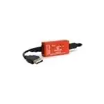
FIGURE 2-1:
2015 Microchip Technology Inc.
MCP2200 USB to UART with Isolation Demo Board
DS50002352A-page 13
�MCP2200 USB to UART with Isolation Demo Board User’s Guide
2.3
SOFTWARE OPERATION
The board operates as a USB to UART converter. In addition, the software can be used
to control the I/O lines and set custom configurations.
2.3.1
USB to UART Operation
The board can be connected to a USB host and to a UART signal (or signals) of the
targeted system. If the host application sends a “Set Line Coding” command (sets the
UART baud rate), the MCP2200 will automatically switch to the correct baud rate.
MCP2200 supports the following UART data format: eight data bits, one stop bit,
no parity. Setting other parameters than the supported ones will not return an error, but
the board will still operate using eight data bits, one stop bit and no parity. The “no error
return” behavior was chosen in order to prevent crashes from certain terminal software
that cannot handle properly the rejection of the selected parameters.
2.3.2
Configuration Software
The PC software allows the user to evaluate functionality and set custom
configurations. Figure 2-2 shows the main screen.
FIGURE 2-2:
DS50002352A-page 14
Main Software Screen
2015 Microchip Technology Inc.
�The software is designed to help in the development of custom configurations. The
following functionalities can be modified to meet the custom/user’s requirements:
• Vendor ID (VID) and Product ID (PID): The default VID is 0x04D8, which is
assigned to Microchip by the USB IF. The VID can be changed to another VID if
authorized by the owner of the assignment. Contact the USB IF for more information.
The default PID for the MCP2200 device is 0x00DF and can be used “as-is”.
Microchip’s Vendor ID can be sublicensed by obtaining a new Product ID from
Microchip Technology Inc. See the product or board page for link and instructions
to the sublicensing agreement. This is required only if the Microchip’s Vendor ID is
used. Changing the Vendor ID to another assigned and authorized VID does not
require any sublicensing from Microchip.
• Baud rate: A pull-down box allows a selection of the most commonly used baud
rates.
• I/O Config: This function is a binary 8-bit value that configures the I/O port to
input (logic ‘1’) or output (logic ‘0’).
• Output Default: It is the default value for the port pins configured as output. This
is also an 8-bit binary value.
• Tx/Rx LEDs: By checking this box, the LED functions are enabled on GP6 and
GP7. The “LED Function” and “Blink Duration” must be configured.
• Hardware Flow Control: This function enables the RTS and CTS pins for UART
handshaking. Not used on this board since the pins are not connected.
• USBCFG Pin: Enables the USBCFG pin on GP1. Not used on this board since
the pin is not connected.
• Suspend Pin: Enables the SSPND pin functionality on GP0. Not used on this
board since the pin is not connected.
• UART Polarity: Enables the inverse polarity for the UART pins.
• String Descriptors: Enter custom Manufacturer and Product string descriptors.
• Update VID/PID Button: This button updates the software to use the VID and
PID in the “New” boxes. For example, if the PID is changed to 0xFFFF, the
software will keep using the original 0x00DF until the Update VID/PID button is
pressed. After this, the software will switch to the 0xFFFF PID.
CAUTION
Care must be taken when changing the VID or PID because the software will be unable
to communicate to the board if a mismatch occurs.
2015 Microchip Technology Inc.
DS50002352A-page 15
�MCP2200 USB to UART with Isolation Demo Board User’s Guide
NOTES:
DS50002352A-page 16
2015 Microchip Technology Inc.
�MCP2200 USB TO UART
WITH ISOLATION DEMO BOARD
USER’S GUIDE
Appendix A. Schematics and Layouts
A.1
INTRODUCTION
This appendix contains the following schematics and layouts for the MCP2200 USB to
UART with Isolation Demo Board:
•
•
•
•
Board – Schematic
Board – Top Copper and Silk
Board – Top Copper
Board – Bottom Copper
2015 Microchip Technology Inc.
DS50002352A-page 17
�BOARD – SCHEMATIC
DATAVIEW PO RT
USB
5V_USB
5V_USB
C1
5V_USB
4.7k
0603
X1
C5
12 MHz
18 pF
0603
GND_USB
C6
18 pF
0603
GND_USB
GND_USB
1
2
3
4
5
6
7
8
9
10
U1
VDD
VSS
OSC1
D+
OSC2
DRST
VUSB
GP7/TxLED GP0
GP6/RxLED GP1
GP5
GP2
GP4
CTS
GP3
RX
TX
RTS
MCP2200
R2
R3
1k
0603
1k
0603
USB_N
USB_P
20
19
18
17
16
15
14
13
12
11
GND_USB
USB_P
USB_N
GND_USB
LD1
LD2
RED
J1
USB MINI-B Female
GND_USB
0.1 uF
0603
GND_USB
MCP2200_RX
MCP2200_TX
5V_USB
5V_USB
3.3D
U2
1
VDD1
2
VOA
3
VIB
4
GND1
J2
8
VDD2
7
VIA
6
VOB
5
GND2
3.3D
RX
TX
3.3D
FOD8012
GND_USB
GND_USB
R4
1k
0603
GND
C4
0.1 uF
0603
LD3
0.1 uF
0603
GREEN
GND
GND
5V_USB
VBUS
DD+
ID
GND
C2
C3
GREEN
1
2
3
4
5
0
R1
0.1 uF
0603
MCP2200
6
5
4
3
2
1
RX
GND
3.3D
TX
HDR-2.54 Female 1x6
PICkit ™ Serial
2015 Microchip Technology Inc.
MCP2200 USB to UART with Isolation Demo Board User’s Guide
DS50002352A-page 18
A.2
�A.3
BOARD – TOP COPPER AND SILK
A.4
BOARD – TOP COPPER
A.5
BOARD – BOTTOM COPPER
2015 Microchip Technology Inc.
DS50002352A-page 19
�MCP2200 USB to UART with Isolation Demo Board User’s Guide
NOTES:
DS50002352A-page 20
2015 Microchip Technology Inc.
�MCP2200 USB TO UART
WITH ISOLATION DEMO BOARD
USER’S GUIDE
Appendix B. Bill of Materials (BOM)
TABLE B-1:
BILL OF MATERIALS (BOM)
Qty
Reference
4
C1, C2, C3, C4
Cap. ceramic 0.1 µF 16V 10% X7R SMD
0603
2
C5, C6
Cap. ceramic 18 pF 50V 5% NP0 SMD 0603 Kemet®
C0603C180J5GACTU
1
CBL1
Mech. HW cable USB-A Male to Mini
USB-B Male 3 ft Black
Katerno
10UM-02103BK
1
J1
Conn. USB Mini-B Female SMD R/A
Hirose Electric Co.,
Ltd.
UX60-MB-5ST
1
J2
PPPC061LGBN-RC
2
LD1, LD3
Conn. HDR-2.54 Female 1x6 Gold TH R/A Sullins Connector
Solutions
Diode LED Green 2.2V 25 mA 10 mcd
Kingbright Corp.
Diffuse RAD 1.8 mm
1
LD2
Diode LED Red 1.85V 30 mA 200 mcd
Diffuse RAD 1.8 mm
Kingbright Corp.
WP4060SRD
3
M1, M2, M3
Mech. HW stand-off LED T1-3/4 0.120"
Black
Bivar, Inc.
LTM-120
1
R1
Res. TKF 4.7k 5% 1/10W SMD 0603
Yageo Corporation
3
R2, R3, R4
Res. TKF 1k 5% 1/10W SMD 0603
Panasonic - ECG
ERJ-3GEYJ102V
1
U1
MCHP Interface USB UART
MCP2200-I/SS SSOP-20
MCP2200-I/SS
1
U2
IC Photo FOD8012 Bi-Dir 3.3V and 5V
SOIC-8
Microchip
Technology Inc.
Fairchild
Semiconductor®
1
X1
Crystal 12 MHz 18 pF SMD HC49/US
Abracon®
Corporation
ABLS-12.000MHZ-B4-T
1
Enclosure
Custom Enclosure
—
N/A
Note 1:
Description
Manufacturer
Samsung
Electro-Mechanics
America, Inc.
®
Part Number
CL10B104KO8NNNC
WP4060GD
RC0603JR-074K7L
FOD8012
The components listed in this Bill of Materials are representative of the PCB assembly. The
released BOM used in manufacturing uses all RoHS-compliant components.
2015 Microchip Technology Inc.
DS50002352A-page 21
�Worldwide Sales and Service
AMERICAS
ASIA/PACIFIC
ASIA/PACIFIC
EUROPE
Corporate Office
2355 West Chandler Blvd.
Chandler, AZ 85224-6199
Tel: 480-792-7200
Fax: 480-792-7277
Technical Support:
http://www.microchip.com/
support
Web Address:
www.microchip.com
Asia Pacific Office
Suites 3707-14, 37th Floor
Tower 6, The Gateway
Harbour City, Kowloon
Hong Kong
Tel: 852-2943-5100
Fax: 852-2401-3431
China - Xiamen
Tel: 86-592-2388138
Fax: 86-592-2388130
China - Zhuhai
Tel: 86-756-3210040
Fax: 86-756-3210049
Austria - Wels
Tel: 43-7242-2244-39
Fax: 43-7242-2244-393
Denmark - Copenhagen
Tel: 45-4450-2828
Fax: 45-4485-2829
India - Bangalore
Tel: 91-80-3090-4444
Fax: 91-80-3090-4123
France - Paris
Tel: 33-1-69-53-63-20
Fax: 33-1-69-30-90-79
India - New Delhi
Tel: 91-11-4160-8631
Fax: 91-11-4160-8632
Germany - Dusseldorf
Tel: 49-2129-3766400
Atlanta
Duluth, GA
Tel: 678-957-9614
Fax: 678-957-1455
Austin, TX
Tel: 512-257-3370
Boston
Westborough, MA
Tel: 774-760-0087
Fax: 774-760-0088
Chicago
Itasca, IL
Tel: 630-285-0071
Fax: 630-285-0075
Cleveland
Independence, OH
Tel: 216-447-0464
Fax: 216-447-0643
Australia - Sydney
Tel: 61-2-9868-6733
Fax: 61-2-9868-6755
China - Beijing
Tel: 86-10-8569-7000
Fax: 86-10-8528-2104
China - Chengdu
Tel: 86-28-8665-5511
Fax: 86-28-8665-7889
China - Chongqing
Tel: 86-23-8980-9588
Fax: 86-23-8980-9500
China - Dongguan
Tel: 86-769-8702-9880
China - Hangzhou
Tel: 86-571-8792-8115
Fax: 86-571-8792-8116
India - Pune
Tel: 91-20-3019-1500
Japan - Osaka
Tel: 81-6-6152-7160
Fax: 81-6-6152-9310
Japan - Tokyo
Tel: 81-3-6880- 3770
Fax: 81-3-6880-3771
Korea - Daegu
Tel: 82-53-744-4301
Fax: 82-53-744-4302
China - Hong Kong SAR
Tel: 852-2943-5100
Fax: 852-2401-3431
Korea - Seoul
Tel: 82-2-554-7200
Fax: 82-2-558-5932 or
82-2-558-5934
China - Nanjing
Tel: 86-25-8473-2460
Fax: 86-25-8473-2470
Malaysia - Kuala Lumpur
Tel: 60-3-6201-9857
Fax: 60-3-6201-9859
Detroit
Novi, MI
Tel: 248-848-4000
China - Qingdao
Tel: 86-532-8502-7355
Fax: 86-532-8502-7205
Malaysia - Penang
Tel: 60-4-227-8870
Fax: 60-4-227-4068
Houston, TX
Tel: 281-894-5983
China - Shanghai
Tel: 86-21-5407-5533
Fax: 86-21-5407-5066
Philippines - Manila
Tel: 63-2-634-9065
Fax: 63-2-634-9069
China - Shenyang
Tel: 86-24-2334-2829
Fax: 86-24-2334-2393
Singapore
Tel: 65-6334-8870
Fax: 65-6334-8850
China - Shenzhen
Tel: 86-755-8864-2200
Fax: 86-755-8203-1760
Taiwan - Hsin Chu
Tel: 886-3-5778-366
Fax: 886-3-5770-955
China - Wuhan
Tel: 86-27-5980-5300
Fax: 86-27-5980-5118
Taiwan - Kaohsiung
Tel: 886-7-213-7828
Dallas
Addison, TX
Tel: 972-818-7423
Fax: 972-818-2924
Indianapolis
Noblesville, IN
Tel: 317-773-8323
Fax: 317-773-5453
Los Angeles
Mission Viejo, CA
Tel: 949-462-9523
Fax: 949-462-9608
New York, NY
Tel: 631-435-6000
San Jose, CA
Tel: 408-735-9110
Canada - Toronto
Tel: 905-673-0699
Fax: 905-673-6509
China - Xian
Tel: 86-29-8833-7252
Fax: 86-29-8833-7256
Germany - Munich
Tel: 49-89-627-144-0
Fax: 49-89-627-144-44
Germany - Pforzheim
Tel: 49-7231-424750
Italy - Milan
Tel: 39-0331-742611
Fax: 39-0331-466781
Italy - Venice
Tel: 39-049-7625286
Netherlands - Drunen
Tel: 31-416-690399
Fax: 31-416-690340
Poland - Warsaw
Tel: 48-22-3325737
Spain - Madrid
Tel: 34-91-708-08-90
Fax: 34-91-708-08-91
Sweden - Stockholm
Tel: 46-8-5090-4654
UK - Wokingham
Tel: 44-118-921-5800
Fax: 44-118-921-5820
Taiwan - Taipei
Tel: 886-2-2508-8600
Fax: 886-2-2508-0102
Thailand - Bangkok
Tel: 66-2-694-1351
Fax: 66-2-694-1350
01/27/15
DS50002352A-page 22
2015 Microchip Technology Inc.
�


 工商网监
湘ICP备2023018690号
工商网监
湘ICP备2023018690号
