RN-41-SM / RN-42-SM
www.rovingnetworks.com
rn-41sm-ds 7/12/2010
Class 1 / Class 2 Bluetooth®
Socket Module
Features
•
Socket module with UART interface
•
3.3/5V logic CMOS I/O (RS-232 as well)
•
Fully qualified Bluetooth 2.1/2.0/1.2/1.1 module
•
•
Bluetooth v2.1+EDR support
Low power (8-30mA connected, 2mA idle)
•
UART supports baud rates from 1200 to 3Mbit
•
Sustained SPP data rates - 240Kbps (slave),
300Kbps (master)
•
HCI data rates - 1.5Mbps sustained, 3.0Mbps
burst in HCI mode
•
HCI mode, or SPP/DUN software stacks
available.
•
Embedded Bluetooth stack profiles included
(requires no host stack): GAP, SDP, RFCOMM
and L2CAP, with SPP, DUN and HID profiles.
•
RS232 on board with power enable on IO pin.
•
Bluetooth SIG Qualified, End Product Listing
•
Class 1 high power amplifier (RN-41-SM only)
with on board ceramic RF chip antenna.
o Certifications: FCC, ICS, CE
o Environmentally friendly, RoHS compliant
Applications
•
•
•
•
•
•
Cable replacement
Barcode scanners
Measurement and monitoring systems
Industrial sensors and controls
Medical devices
Asset tacking
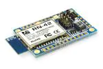
Description
The RN-41-SM / RN-42-SM is a though hole, low
power and highly flexible Bluetooth socket module .
This module supports SPP/DUN and HCI Bluetooth
interface protocols, is simple to design in and fully
certified. With its high performance on chip antenna
and support for Bluetooth® Enhanced Data Rate
(EDR), the RN-41 / RN-42 delivers up to 3 Mbps data
rate for distances to 100M / 20M. The RN-41/RN-42
socket module is the perfect method for adding
Bluetooth wireless capability to existing products
without redesign, saving you significant time and
money.
Block Diagram
Crystal
VCC
GND
RF
Switch
CSR BlueCore-04
External
PA
BALUN
PIO4
PIO5
PIO6
USB
UART
PCM
Flash
Memory
809 University Avenue • Los Gatos, CA 95032 • Tel (408) 395-6539 • info@RovingNetworks.com
�RN-41-SM/RN-42-SM Data Sheet
www.rovingnetworks.com
7/12/2010
Overview
•
•
•
•
•
•
•
•
•
•
Baud rate speeds: 1200bps up to 921Kbps, non-standard baud rates can be programmed.
RN-41: Class 1 radio, 330’ (100m) distance, 12dBm output transmitter, -80dBm typical receive sensitivity
RN-42: Class 2 radio, 60’ (20m) distance, 4dBm output transmitter, -80dBm typical receive sensitivity
Frequency 2402 ~ 2480MHz,
FHSS/GFSK modulation, 79 channels at 1MHz intervals
Secure communications, 128 bit encryption
Error correction for guaranteed packet delivery
UART local and over-the-air RF configuration
Auto-discovery/pairing requires no software configuration (instant cable replacement).
Auto-connect master, IO pin (DTR) and character based trigger modes
Environmental Conditions
Parameter
Temperature Range (Operating)
Temperature Range (Storage)
Relative Humidity (Operating)
Relative Humidity (Storage)
Value
o
o
-40 C ~ 85 C
o
o
-40 C ~ 85 C
≤90%
≤90%
Electrical Characteristics (RN-41-SM)
Parameter
Supply Voltage (DC)
Min
3.0
RX Supply Current
TX Supply Current
Typ.
3.3
35
65
Max.
3.3V on
Header A,
16V on
Header B
60
85
Unit
V
mA
mA
Average power consumption
Standby/Idle (default settings)
Connected (normal mode)
Connected (low power Sniff)
Standby/Idle (Deep sleep enabled)
250uA
25
30
8
2.5
mA
mA
mA
mA
Electrical Characteristics (RN-42-SM)
Parameter
Supply Voltage (DC)
Min
3.0
Typ.
3.3
Max.
3.3V on
Header A,
16V on
Header B
Unit
V
Average power consumption
Radio ON* (Discovery or Inquiry
window time)
Connected Idle (No Sniff)
Connected Idle (Sniff 100 milli secs)
Connected with data transfer
Deep Sleep Idle mode
40
40
mA
25
12
45
26
mA
mA
mA
uA
50
809 University Avenue • Los Gatos, CA 95032 • Tel (408) 395-6539 • info@RovingNetworks.com
~2~
�RN-41-SM/RN-42-SM Data Sheet
www.rovingnetworks.com
7/12/2010
Radio Characteristics (RN-41)
Parameter
Sensitivity @ 0.1%BER
RF Transmit Power
Initial Carrier Frequency
Tolerance
Freq.
(GHz)
2.402
2.441
2.480
2.402
2.441
2.480
2.402
2.441
2.480
20dB bandwidth for modulated
carrier
Drift (Five slots packet)
Drift Rate
∆f1avg Max Modulation
∆f2avg Min Modulation
2.402
2.441
2.480
2.402
2.441
2.480
Min
Typ
Max
Bluetooth
Specification
15.0
15.0
15.0
-
-80
-80
-80
16.0
16.0
16.0
5
5
5
-86
-86
-86
≤ -70
75
75
75
75
-
900
1000
≤ 1000
kHz
140
140
140
140
140
140
15
13
165
165
165
190
190
190
175
175
175
-
40
20
kHz
kHz
kHz
kHz
kHz
kHz
kHz
kHz
Min
Typ
Max
0
0
0
-
-80
-80
-80
2
2
2
5
5
5
-86
-86
-86
4
4
4
75
75
75
-
900
1000
≤ 1000
kHz
140
140
140
140
140
140
15
13
165
165
165
190
190
190
175
175
175
-
40
20
kHz
kHz
kHz
kHz
kHz
kHz
kHz
kHz
≤ 15
>140
115
Units
dBm
dBm
dBm
dBm
dBm
dBm
kHz
kHz
kHz
Radio Characteristics (RN-42)
Parameter
Sensitivity @ 0.1%BER
RF Transmit Power
Initial Carrier Frequency
Tolerance
Freq.
(GHz)
2.402
2.441
2.480
2.402
2.441
2.480
2.402
2.441
2.480
20dB bandwidth for modulated
carrier
Drift (Five slots packet)
Drift Rate
∆f1avg Max Modulation
∆f2avg Min Modulation
2.402
2.441
2.480
2.402
2.441
2.480
Bluetooth
Specification
≤ -70
≤4
75
>140
115
Units
dBm
dBm
dBm
dBm
dBm
dBm
kHz
kHz
kHz
809 University Avenue • Los Gatos, CA 95032 • Tel (408) 395-6539 • info@RovingNetworks.com
~3~
�RN-41-SM/RN-42-SM Data Sheet
www.rovingnetworks.com
7/12/2010
Pin Description
NOTE: The RN-41 and the RN-42 are pin and functionally compatible.
Header A
1
2
3
4
5
6
7
8
9
10
11
12
RN-41-SM/
RN-42-SM
Top View
Header A
24
23
22
21
20
19
18
17
16
15
14
13
1 2 3 4 5 6
Header B
3/5V TTL signaling
5-16 VDC power
Signals on Header A except pins 4, 5, 6 and 7 have the following logic levels.
Input logic level LOW is from -0.4 v to 0.8 V, input high is from 2.1 to 3.4V.
Output logic level LOW max is 0.2 and output HIGH is minimum is 2.8.
All I/O’s except reset default to weak pull down.
Header A
Pin
Name
Description
Default State
1
2
PIO6
PIO7
Input with weak pulldown
Input with weak pulldown
3
4
5
6
7
8
RESET
RX
TX
RTS
CTS
VB2
9
10
SHUT
DOWN
PRS
Set BT master (HIGH=auto-master mode)
Set Baud rate (HIGH = force 9600, LOW = 115K or firmware
setting)
Active LOW reset
RS232 receive input (see note below)
RS232 transmit output (see note below)
RS232 RTS (see note below)
RS232 CTS (see note below)
Analog battery monitor signal (Not currently supported in
firmware)
Shuts down power to the entire module.
11
12
VCC 3.3
GND
Input to RN41 with 1K pullup
No Connect
Active LOW
RS232 power
Short to pin 11 VCC to enable RS232
3.3V regulated power input
Ground
809 University Avenue • Los Gatos, CA 95032 • Tel (408) 395-6539 • info@RovingNetworks.com
~4~
�RN-41-SM/RN-42-SM Data Sheet
www.rovingnetworks.com
7/12/2010
13
14
15
16
17
18
19
20
VB1
PIO8
PIO9
PIO10
PIO11
RXDB
TXDB
RTSB
Analog battery monitor signal
Status (RF data rx/tx)
IO
IO (remote DTR signal)
IO (remote RTS signal )
UART receive
UART transmit
UART RTS, goes HIGH to disable host transmitter
No Connect
Output
Input with weak pulldown
Input with weak pulldown
Input with weak pulldown
Input
Output
Output
21
22
23
24
CTSB
PIO2
PIO3
PIO4
UART CTS, if set HIGH, disables TX transmitter
Status, HIGH when connected, LOW otherwise
Auto discovery = HIGH
Set factory defaults
input
Output from RN41
Input t with weak pulldown
Input with weak pulldown
Note: When connecting to the RS232 signals on header A: You must connect pin 10 (PRS) to pin 11
(VCC). This powers the RS232 chip. Also make sure that R6 and R8 are installed (default condition).
Header B
1
2
3
4
5
6
RX
TX
RTS
CTS
VDD
GND
Receive UART
Input to module
Transmit UART
RTS UART, goes HIGH to disable host transmitter
CTS UART, if set HIGH, disables transmitter
5-16 VDC
Ground
Output from module
Tie to RTS if NOT driven
Note: To use Header B you must remove resistors R6 and R8. Removing these resistors disconnects
the RX (header A pin 4) and CTS (header A pin 7) signals from the RS232 chip.
R6
R8
809 University Avenue • Los Gatos, CA 95032 • Tel (408) 395-6539 • info@RovingNetworks.com
~5~
�RN-41-SM/RN-42-SM Data Sheet
www.rovingnetworks.com
7/12/2010
Jumper Settings
The bank of headers on the top of the module control PIO4,
PIO5, PIO6 and PIO7 and correspond directly to the external
switches on the Firefly Bluetooth serial adapter.
Default Baudrate
Auto Master
Auto Discovery
Factory Reset
Default Baudrate
OFF = 115K (can be overridden by software baud rate configuration command),
ON = 9600 (ignores software baudrate configuration)
Auto Discovery
In slave mode, sets a special class of device that is used the master to auto connect. If
Switch 3 also ON, the device performs a search, stores, and connects to a remote slave
which has this switch 2 set.
Auto Master
Device acts as Bluetooth master, auto-connects to a stored remote address. First set the
Bluetooth address of the slave device using the SR command or through instant cable
replacement settings.
Restore Factory Defaults Set this switch ON, power up unit, and toggle the switch from ON to OFF 3 times to
return the unit to factory settings.
Status LEDs
The Green LED indicates the status of the Bluetooth connection and when the device is in configuration mode.
MODE
GREEN LED
Fast, 10 x per second
2 times per second
1 time per second
On Solid
In Configuration mode
Boot up, Remote Configurable
Discoverable/Idle
Connected
RED LED
Data over the UART
809 University Avenue • Los Gatos, CA 95032 • Tel (408) 395-6539 • info@RovingNetworks.com
~6~
�RN-41-SM/RN-42-SM Data Sheet
www.rovingnetworks.com
7/12/2010
Hardware Connections and Power
Placing 3.3Vdc into the PIO’s outputs will permanently damage the radio modules. The failure mode is short
across GND and VCC. Use a 10KΩ resistor in series or a 10KΩ pull up resistor for input and output PIO’s
respectively.
•
•
•
Make sure to connect a common ground when using the external TX, RX inputs 0 – 3.3Vdc.
For a 3 wire DB-9 interface (tx, rx, gnd only) connect/short CTS to RTS, Factory default is hardware flow
control enabled CTS and RTS connected.
When using a 5.0Vdc Input, PIO’s require a voltage divider. A good choice is 10K ohm series with 20K to
Ground. PIO’s are 0-3.3Vdc not 5 volt tolerant.
Hardware Communications Connections for Modules
RN-41-SM / RN-42-SM TX � RX of the application Micro Controller Unit (MCU)
RN-41-SM / RN-42-SM RX TX of the application Micro Controller Unit (MCU)
RN-41-SM / RN-42-SM RTS � CTS of the application Micro Controller Unit (MCU)
RN-41-SM / RN-42-SM CTS RTS of the application Micro Controller Unit (MCU)
809 University Avenue • Los Gatos, CA 95032 • Tel (408) 395-6539 • info@RovingNetworks.com
~7~
�RN-41-SM/RN-42-SM Data Sheet
www.rovingnetworks.com
7/12/2010
Mechanical Dimensions
0.900
0.820
0.080
Hole Dia.
0.100
0.200
Hole Dia.
0.032
Pad Dia.
0.050
0.080
1.300
RN-41-SM / RNTop View
1.230
0.100
0.080
0.050
0.050
Hole Dia.
0.035
Pad Dia.
0.060
0.200
0.850
809 University Avenue • Los Gatos, CA 95032 • Tel (408) 395-6539 • info@RovingNetworks.com
~8~
�RN-41-SM/RN-42-SM Data Sheet
www.rovingnetworks.com
7/12/2010
Design Concerns
1. Reset circuit. RN-41-SM / RN-42-SM contains a 1k pullup to VCC, the polarity of reset on the RN-41 / RN-42 is
ACTIVE LOW. A power on reset circuit with delay is OPTIONAL on the reset pin of the module. It should only be
required if the input power supply has a very slow ramp, or tends to bounce or have instability on power up. Use
microcontroller GPIO to control reset once power is stable. Also can be driven from low cost power supervisor
chips available, such as MCP809, MCP102/121, and Torex XC61F.
2. Factory reset PIO4. Connect this pin to a switch, or jumper, or resistor for access. Can be used to reset the
module to FACTORY DEFAULTS and is often critical in situations where the module has been mis-configured. To
set Factory defaults: set pin HIGH, apply power, then toggle 4 times.
3. Connection status. PIO2 is an output which directly reflects the connection state, it goes HIGH when
connected, and LOW otherwise.
4. HCI mode. The RN41-SM module must be loaded with special firmware to run in HCI mode. When in HCI mode
the standard SPP/DUN applications are disabled.
5. Shutdown mode. Pin 9 Shutdown has a pullup to 3.3V. If you pull this pin LOW it shuts down the on board
regulator putting the module in micropower mode. Shutdown also turns off the power to the RS-232 chip so you
can hook the module to a battery and a remote microcontroller like a PIC you can go super low power, wake up
connect send data go to sleep.
6. Minimizing Radio interference The areas under the antenna should not have surface traces, GND planes, or
exposed vias,or metal enclosures for optimal radio performance the antenna
Compliance Information
Category
Radio
Country
USA
FCC ID:
Standard
FCC CFR47 Part 15 C, para 15.247
T9J-R41-1
EUROPE
EN 300 328-1
EN 300 328-2 2.4GHz
CANADA
IC Canada ID:
IC RSS-210 low power comm. device
6514A-RN411
EMC
USA
EUROPE
FCC CFR47 Part 15 subclass B
EN 55022 Class B radiated
EN61000-4-2 ESD immunity
EN61000-4-3 radiated field
EN61000-4-6 RF immunity
EN61000-4-8 power magnetic immunity
Bluetooth
LISTED
B013180
Environmental
RoHS
RoHS compliant
809 University Avenue • Los Gatos, CA 95032 • Tel (408) 395-6539 • info@RovingNetworks.com
~9~
�RN-41-SM/RN-42-SM Data Sheet
www.rovingnetworks.com
7/12/2010
Ordering Information
Part Number
RN-41-SM
RN-42-SM
Description
Socket module with RN-41 (Class 1), No headers installed. Standard 3/5 V
UART and RS232 interface, firmware (SPP/DUN Master and Slave)
Socket module with RN-42 (Class 2), No headers installed. Standard 3/5 V
UART and RS232 interface, firmware (SPP/DUN Master and Slave)
For other configurations, contact Roving Networks directly.
Visit http://www.rovingnetworks.com/buynow.php for current pricing and a list of distributors carrying our
products.
Copyright © 2009 Roving Networks. All rights reserved.
The Bluetooth trademark and logo are registered trademarks and are owned by the Bluetooth SIG, Inc. All other
trademarks are property of their respective owners.
Roving Networks reserves the right to make corrections, modifications, and other changes to its products,
documentation and services at any time. Customers should obtain the latest relevant information before placing
orders and should verify that such information is current and complete.
Roving Networks assumes no liability for applications assistance or customer product design. Customers are
responsible for their products and applications using Roving Networks components. To minimize the risks associated
with customer products and applications, customers should provide adequate design and operating safeguards.
Roving Networks products are not authorized for use in safety-critical applications (such as life support) where a
failure of the Roving Networks product would reasonably be expected to cause severe personal injury or death,
unless officers of the parties have executed an agreement specifically governing such use.
809 University Avenue • Los Gatos, CA 95032 • Tel (408) 395-6539 • info@RovingNetworks.com
~ 10 ~
�


 工商网监
湘ICP备2023018690号
工商网监
湘ICP备2023018690号
