Data Sheet
ZL30241 Single Channel Precision
Universal Clock Generator and NCO
Ordering Information
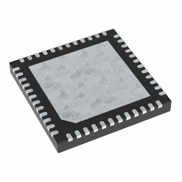
ZL30241LDG1 48 Pin QFN Tray
ZL30241LDF1 48 Pin QFN Tape/Reel
Matte Tin
-40oC to +85oC
Package size: 7 x 7 mm
Features
Outputs
•
PLL
•
•
One PLL with ultra low jitter
–
Up to 275 fs RMS jitter for integer mode
Supports integer, fractional and ratio modes
–
Up to 400 fs RMS jitter for fractional mode
–
Ratio mode for flexible FEC rate support
Inputs
•
Synthesizes two different frequencies from the PLL
Crystals, crystal oscillator or reference (singled ended or
differential) inputs
–
Crystal Input range from 22 MHz to 54 MHz
–
Crystal oscillator or single-ended reference input
from 22 MHz to 180 MHz
–
Differential reference input from 22 to 864 MHz
Configuration
•
Generates clock signals at power-up per user defined
custom configuration (factory programmable)
•
Dynamically configurable
configuration registers
via
SPI
and
•
Each output is independently configurable to support
LVDS, LVPECL, HCSL, LVCMOS
•
Generates any output frequency from 12 MHz to
914 MHz
•
Generates output from crystal, a crystal oscillator or
reference
•
NCO accuracy less than 0.1 ppb in fractional mode
Applications
volatile
•
Clocks for NPUs, FPGAs, 10G CDRs, high-speed ADC,
PCIe interface devices, Ethernet switches and PHYs
•
Timing for optical, storage, networking and broadcast
video applications
Single Ended/
Differential
In_p
In_n
Single Ended/
Differential
Input
Divider
PLL1
Divider
1
Single Ended/
Differential
Divider
2
Single Ended/
Differential
PLL
XO1
Crystal
Input 1
XO2
Figure 1 •
Configuration and
Status
External Filters
SPI
Filter 1
RefOut Enable
RefOut_p
RefOut_n
Output Enable1
Out1_p
Out1_n
Output Enable2
Out2_p
Out2_n
Block Diagram
November 2012
© 2012 Microsemi Corporation
1
�ZL30241
Data Sheet
Table of Contents
1.0 Pin Diagram . . . . . . . . . . . . . . . . . . . . . . . . . . . . . . . . . . . . . . . . . . . . . . . . . . . . . . . . . . . . . . . . . . . . . . . . . . . 5
2.0 Pin Description. . . . . . . . . . . . . . . . . . . . . . . . . . . . . . . . . . . . . . . . . . . . . . . . . . . . . . . . . . . . . . . . . . . . . . . . . 5
3.0 Description . . . . . . . . . . . . . . . . . . . . . . . . . . . . . . . . . . . . . . . . . . . . . . . . . . . . . . . . . . . . . . . . . . . . . . . . . . . . 8
3.1 Input Configuration . . . . . . . . . . . . . . . . . . . . . . . . . . . . . . . . . . . . . . . . . . . . . . . . . . . . . . . . . . . . . . . . . . . 8
3.2 Output Configuration . . . . . . . . . . . . . . . . . . . . . . . . . . . . . . . . . . . . . . . . . . . . . . . . . . . . . . . . . . . . . . . . . 11
3.2.1 Output Control Pins . . . . . . . . . . . . . . . . . . . . . . . . . . . . . . . . . . . . . . . . . . . . . . . . . . . . . . . . . . . . . 12
3.2.2 Output Electrical Format - (LVCMOS, LVDS, LVPECL, or HCSL). . . . . . . . . . . . . . . . . . . . . . . . . . 12
3.3 Reference Input . . . . . . . . . . . . . . . . . . . . . . . . . . . . . . . . . . . . . . . . . . . . . . . . . . . . . . . . . . . . . . . . . . . . . 12
3.4 Crystal Oscillator . . . . . . . . . . . . . . . . . . . . . . . . . . . . . . . . . . . . . . . . . . . . . . . . . . . . . . . . . . . . . . . . . . . . 13
3.5 PLLs . . . . . . . . . . . . . . . . . . . . . . . . . . . . . . . . . . . . . . . . . . . . . . . . . . . . . . . . . . . . . . . . . . . . . . . . . . . . . 13
3.5.1 Integer Mode . . . . . . . . . . . . . . . . . . . . . . . . . . . . . . . . . . . . . . . . . . . . . . . . . . . . . . . . . . . . . . . . . . 14
3.5.2 Fractional Mode . . . . . . . . . . . . . . . . . . . . . . . . . . . . . . . . . . . . . . . . . . . . . . . . . . . . . . . . . . . . . . . . 14
3.5.3 Ratio Mode. . . . . . . . . . . . . . . . . . . . . . . . . . . . . . . . . . . . . . . . . . . . . . . . . . . . . . . . . . . . . . . . . . . . 14
3.6 Output Dividers . . . . . . . . . . . . . . . . . . . . . . . . . . . . . . . . . . . . . . . . . . . . . . . . . . . . . . . . . . . . . . . . . . . . . 14
3.7 Status Indicators . . . . . . . . . . . . . . . . . . . . . . . . . . . . . . . . . . . . . . . . . . . . . . . . . . . . . . . . . . . . . . . . . . . . 15
3.8 Resets . . . . . . . . . . . . . . . . . . . . . . . . . . . . . . . . . . . . . . . . . . . . . . . . . . . . . . . . . . . . . . . . . . . . . . . . . . . . 15
4.0 SPI Programming . . . . . . . . . . . . . . . . . . . . . . . . . . . . . . . . . . . . . . . . . . . . . . . . . . . . . . . . . . . . . . . . . . . . . . 15
5.0 Register Map . . . . . . . . . . . . . . . . . . . . . . . . . . . . . . . . . . . . . . . . . . . . . . . . . . . . . . . . . . . . . . . . . . . . . . . . . 18
6.0 Detailed Register Map . . . . . . . . . . . . . . . . . . . . . . . . . . . . . . . . . . . . . . . . . . . . . . . . . . . . . . . . . . . . . . . . . . 19
7.0 AC and DC Electrical Characteristics . . . . . . . . . . . . . . . . . . . . . . . . . . . . . . . . . . . . . . . . . . . . . . . . . . . . . 30
8.0 Performance Characteristics . . . . . . . . . . . . . . . . . . . . . . . . . . . . . . . . . . . . . . . . . . . . . . . . . . . . . . . . . . . . 37
9.0 Thermal Characteristics . . . . . . . . . . . . . . . . . . . . . . . . . . . . . . . . . . . . . . . . . . . . . . . . . . . . . . . . . . . . . . . . 38
10.0 Mechanical Drawing . . . . . . . . . . . . . . . . . . . . . . . . . . . . . . . . . . . . . . . . . . . . . . . . . . . . . . . . . . . . . . . . . . 39
2
Microsemi Corporation
�ZL30241
Data Sheet
List of Figures
Figure 1 • Block Diagram . . . . . . . . . . . . . . . . . . . . . . . . . . . . . . . . . . . . . . . . . . . . . . . . . . . . . . . . . . . . . . . . . . . . . 1
Figure 2 - Input Termination - LVCMOS . . . . . . . . . . . . . . . . . . . . . . . . . . . . . . . . . . . . . . . . . . . . . . . . . . . . . . . . . . 9
Figure 3 - Input Termination - LVDS. . . . . . . . . . . . . . . . . . . . . . . . . . . . . . . . . . . . . . . . . . . . . . . . . . . . . . . . . . . . . 9
Figure 4 - Input Termination - LVPECL AC coupled. . . . . . . . . . . . . . . . . . . . . . . . . . . . . . . . . . . . . . . . . . . . . . . . 10
Figure 5 - Input Termination - LVPECL DC coupled. . . . . . . . . . . . . . . . . . . . . . . . . . . . . . . . . . . . . . . . . . . . . . . . 10
Figure 6 - Input Termination - HCSL . . . . . . . . . . . . . . . . . . . . . . . . . . . . . . . . . . . . . . . . . . . . . . . . . . . . . . . . . . . 11
Figure 7 - Output Enable/Disable. . . . . . . . . . . . . . . . . . . . . . . . . . . . . . . . . . . . . . . . . . . . . . . . . . . . . . . . . . . . . . 11
Figure 8 - Example SPI Read . . . . . . . . . . . . . . . . . . . . . . . . . . . . . . . . . . . . . . . . . . . . . . . . . . . . . . . . . . . . . . . . 16
Figure 9 - Read (opcode 2) cycle. . . . . . . . . . . . . . . . . . . . . . . . . . . . . . . . . . . . . . . . . . . . . . . . . . . . . . . . . . . . . . 16
Figure 10 - Write (opcode 1) cycle . . . . . . . . . . . . . . . . . . . . . . . . . . . . . . . . . . . . . . . . . . . . . . . . . . . . . . . . . . . . . 17
Figure 11 - Switching Waveforms . . . . . . . . . . . . . . . . . . . . . . . . . . . . . . . . . . . . . . . . . . . . . . . . . . . . . . . . . . . . . 33
Figure 12 - LVDS Output Load & Test Circuit. . . . . . . . . . . . . . . . . . . . . . . . . . . . . . . . . . . . . . . . . . . . . . . . . . . . . 33
Figure 13 - LVCMOS Output Load & Test Circuit. . . . . . . . . . . . . . . . . . . . . . . . . . . . . . . . . . . . . . . . . . . . . . . . . . 34
Figure 14 - LVPECL Output Load & Test Circuit . . . . . . . . . . . . . . . . . . . . . . . . . . . . . . . . . . . . . . . . . . . . . . . . . . 34
Figure 15 - HCSL Output Loads & Test Circuits. . . . . . . . . . . . . . . . . . . . . . . . . . . . . . . . . . . . . . . . . . . . . . . . . . . 34
Figure 16 - Serial Peripheral Interface Timing - Master Read (opcode 2) cycle . . . . . . . . . . . . . . . . . . . . . . . . . . 36
Figure 17 - Serial Peripheral Interface Timing - Master Write (opcode 1) cycle. . . . . . . . . . . . . . . . . . . . . . . . . . . 36
3
Microsemi Corporation
�ZL30241
Data Sheet
List of Tables
Table 1 - Pin Description . . . . . . . . . . . . . . . . . . . . . . . . . . . . . . . . . . . . . . . . . . . . . . . . . . . . . . . . . . . . . . . . . . . . . 5
Table 2 - Input modes . . . . . . . . . . . . . . . . . . . . . . . . . . . . . . . . . . . . . . . . . . . . . . . . . . . . . . . . . . . . . . . . . . . . . . . 8
Table 3 - Output modes . . . . . . . . . . . . . . . . . . . . . . . . . . . . . . . . . . . . . . . . . . . . . . . . . . . . . . . . . . . . . . . . . . . . . 11
Table 5 - Xtal_gain[3:0] Values. . . . . . . . . . . . . . . . . . . . . . . . . . . . . . . . . . . . . . . . . . . . . . . . . . . . . . . . . . . . . . . . 13
Table 4 - Reference Input (In_p/In_n) Selection . . . . . . . . . . . . . . . . . . . . . . . . . . . . . . . . . . . . . . . . . . . . . . . . . . 13
Table 6 - Interpretation of S Parameter in Ratio Mode. . . . . . . . . . . . . . . . . . . . . . . . . . . . . . . . . . . . . . . . . . . . . . 14
Table 7 - SPI Operation Codes . . . . . . . . . . . . . . . . . . . . . . . . . . . . . . . . . . . . . . . . . . . . . . . . . . . . . . . . . . . . . . . 16
Table 8 - Register Map . . . . . . . . . . . . . . . . . . . . . . . . . . . . . . . . . . . . . . . . . . . . . . . . . . . . . . . . . . . . . . . . . . . . . . 18
Table 9 - Thermal Care . . . . . . . . . . . . . . . . . . . . . . . . . . . . . . . . . . . . . . . . . . . . . . . . . . . . . . . . . . . . . . . . . . . . . 38
4
Microsemi Corporation
�Data Sheet
ZL30241
Pin Diagram
48
47
46
45
44
43
42
41
40
39
38
37
VDDA6
VDD
NC
NC
RefOut_p
RefOut_n
In_p
In_n
In_VCM
XO1
XO2
VDDA5
1.0
1
2
3
4
5
6
7
8
9
10
11
12
36
35
34
33
32
31
30
29
28
27
26
25
48 Pin QFN
(Top View)
7mm x 7mm Package
Pin Pitch 0.5mm
VSS
NC
NC
NC
NC
VDDA4
NC
NC
NC
NC
PD1_b
VDDA3
FILTER1+
FILTER1OE1
OE2
SDO
CSB\PROG
SCK
SDI
NC
NC
NC
NC
13
14
15
16
17
18
19
20
21
22
23
24
VSSO1
OUT1_p
OUT1_n
VDDO1
VDDA1
VDDO2
OUT2_p
OUT2_n
VSSO2
VSS
OEREF
VDDA2
2.0
Pin Description
Pin Name
48
QFN
Pin #
Name
In_p
In_n
42
41
Input
In_VCM
40
Input Bias
XO1
XO2
39
38
OUT1_p
OUT1_n
2
3
Type
INPUT
Selectable
Description
Input (singled ended or differential).
Can be selected as the reference clock for
PLL1, and/or the Reference Clock Output.
When not used for a single ended crystal
oscillator, it can be differential with a DC bias
provided by the In_VCM pin.
DC
When In_p/In_n act as a differential input, this
pin connects to the midpoint of the two 50 ohm
internal termination resistors.
Crystal Input 1
INPUT
External Crystal should be connected to these
pins to drive the internal oscillator reference.
This input can be used as the reference for
PLL1 and/or the Reference Clock Output.
Clock Output 1
OUTPUT
Clock Output derived from PLL1. Supports
frequencies up to the device maximum. When
used in LVCMOS mode, OUT1_p is the active
pin and OUT1_n is not used and is High-Z.
Selectable1
Table 1 - Pin Description
5
Microsemi Corporation
�Data Sheet
ZL30241
Pin Name
48
QFN
Pin #
Name
Type
Description
INPUT
LVCMOS
Output Enable for Clock Output 1. Active High,
When the output is disabled, it places OUT1_p
& OUT1_n into High-Z state.
This pin is internally pulled-up to VDD through
75 kohms.
OUTPUT
Selectable1
Clock Output derived from PLL1. Supports
frequencies up to the device maximum. When
used in LVCMOS mode, OUT2_p is the active
pin. OUT2_n is not used and is High-Z.
INPUT
LVCMOS
Output Enable for Clock Output 2. Active High,
When the output is disabled, it places OUT2_p
& OUT2_n into High-Z state.
This pin is internally pulled-up to VDD through
75 kohms.
OUTPUT
Selectable1
Reference Clock Output. Provides a copy of the
Reference Input (or Crystal input) frequency.
OE1
15
Output Enable 1
OUT2_p
OUT2_n
7
8
Clock Output 2
OE2
16
Output Enable 2
RefOut_p
RefOut_n
44
43
Reference
Output
OEREF
11
Output Enable for
REFOUT
INPUT
LVCMOS
Output Enable for Reference Output. Active
High.
When the output is disabled, it places RefOut_p
& RefOut_n into High-Z state.
This pin is internally pulled-up to VDD through
50 kohms.
SCK
19
Serial Clock
INPUT
LVCMOS
Clock Input for SPI control.
SDI
20
Serial Data In
INPUT
LVCMOS
Data Input for SPI control.
SDO
17
Serial Data Out
OUTPUT
LVCMOS
Data Output for SPI control.
CSB
18
Chip Select
INPUT
LVCMOS
Chip Select for SPI control.
This pin also functions as a programming pin for
the internal fuses. If this pin is held above 3.3 V,
then the device will accept SPI commands to
program internal fuses.
This pin is internally pulled-up to VDD through
75 kohms.
FILTER1+
FILTER1-
13
14
PLL1 Filter
Analog
CP external Filter capacitor input and return for
PLL1
PD1_b
26
Power Down 1
(Inverted)
INPUT
LVCMOS
Active Low Power Down pin for PLL1. When
active, PLL1 enters power down state; all
outputs from PLL1 are disabled, High-Z.
This pin is internally pulled-down to VSS
through 50 kohms.
Table 1 - Pin Description
6
Microsemi Corporation
�Data Sheet
ZL30241
Pin Name
48
QFN
Pin #
Name
Type
Description
VDD
47
Core Power
SUPPLY
+Power
VSS
10, 36
Device GND
-Power
VDDA1
VDDA2
VDDA3
VDDA4
VDDA5
VDDA6
5
12
25
31
37
48
Analog Power
SUPPLY
+Power
2.5 V or 3.3 V Analog Power Supply
VDDO1
VDDO2
4
6
Clock Output
Power Supply
SUPPLY
+Power
Respective Power Supply pins for individual
Clock Outputs.
VSSO1
VSSO2
1
9
Clock Output
GND’s
-Power
Return path GND pins for respective Clock
Outputs
NC
21, 22,
23, 24,
27, 28,
29, 30,
32, 33,
34, 35,
45, 46
No connection
NC
2.5 V or 3.3 V Power Supply for device core.
Device GND
Leave unconnected
Table 1 - Pin Description
1
Selectable Pins can be programmed to support LVCMOS, LVDS, LVPECL or HCSL.
7
Microsemi Corporation
�Data Sheet
ZL30241
3.0
Description
The ZL30241 is a single PLL clock generator with two programmable outputs. The PLL with either a crystal, crystal
oscillator or external reference input frequency, produce up to two related output frequencies. Each output can
select between LVCMOS, LVDS, LVPECL, and HCSL. The input crystal is a low cost fundamental mode type, and
the ZL30241 provides programmable gain and load capacitors for the crystal inputs. Alternatively, a multi-standard
input reference can be used with a dedicated divider. The crystal or external reference is also available as an output
bypassing the PLL for test purposes.
For the PLL, three modes of operation can be selected: integer mode, fractional mode, and ratio mode. The integer
mode provides lowest noise and behaves like a conventional PLL with whole number dividers. The device will get
interger mode performance even with 3 fractional bits in use allowing eights in the feedback divider without
increasing the jitter.
The fractional mode allows the feedback divider to have an 8 bit integer part and 28 bit fractional part, resulting in a
frequency resolution of 0.1 ppb or better. Finally, the ratio mode offers frequency translation of an N + X/Y nature,
ideal for frequency translation applications like SONET and OTN.
The PLL has a VCO that operates between 3053 MHz and 3677 MHz. There are two output dividers on the PLL,
with a range of 4 to 259. In order to prevent a “frequency hole” between 750.6 MHz and 777.5 MHz, a special
divide by 4.5 mode is also included. Any output frequency between 12 MHz and 914 MHz can be produced on the
differential output.
Additional features include loss of lock indicators and high speed SPI control. The ZL30241 has factory
programmed defaults and may also be configured through the SPI port.
3.1
Input Configuration
The In_p/In_n pins can take one of four modes.
Refmode [1:0]
Mode
00
LVCMOS
01
LVDS
10
LVPECL
11
HCSL
Table 2 - Input modes
8
Microsemi Corporation
�Data Sheet
ZL30241
For LVCMOS mode, the external components are shown in Figure 2..
VDD_driver
VDD
CMOS
Driver
Zo = 50 Ohms
In_p
In_n
NC
In_VCM
1 kohm
Figure 2 - Input Termination - LVCMOS
For LVDS mode, the external components are shown in Figure 3.
VDD_driver
VDD
Zo = 50 Ohms
In_p
LVDS
Driver
In_n
Zo = 50 Ohms
NC
Figure 3 - Input Termination - LVDS
9
Microsemi Corporation
In_VCM
�Data Sheet
ZL30241
For LVPECL mode, the external components are shown in Figure 4 for AC coupled and Figure 5 for DC coupled.
VDD_driver
VDD
500 Ohms
Zo = 50 Ohms
In_p
LVPECL
Driver
In_n
Zo = 50 Ohms
200 Ohms
200 Ohms
In_VCM
500 Ohms
Figure 4 - Input Termination - LVPECL AC coupled
VDD_driver
VDD
Zo = 50 Ohms
In_p
LVPECL
Driver
In_n
Zo = 50 Ohms
In_VCM
50 Ohms
Figure 5 - Input Termination - LVPECL DC coupled
10
Microsemi Corporation
�Data Sheet
ZL30241
For HCSL mode, the external components are shown in Figure 6.
VDD_driver
VDD
Zo = 50 Ohms
In_p
HCSL
Driver
In_n
Zo = 50 Ohms
In_VCM
Figure 6 - Input Termination - HCSL
3.2
Output Configuration
There are three separate output buffers on the ZL30241. The PLL has two outputs and the input frequency can also
bypass the PLL to a additional output buffer. The three buffers can be configured for LVCMOS, LVDS, LVPECL or
HCSL. Each output has an output enable pin (OE), and each output may be enabled or disabled from this pin or a
bit in the register set. For each output, the modes are defined in Table 3.
OutnMode [1:0]
Mode
00
LVCMOS
01
LVDS
10
LVPECL
11
HCSL
Table 3 - Output modes
Each output is by default enabled or disabled by a logical AND of the OEn hardware pin value accessible in register
2 and the SPI bit. The logical behavior of all relevant bits are shown in Figure 7.
OEn_override
0
OEn pin
SPI OEn
1
PU1_b
or SPI for PLL1
VDD for OE[1:2]
VSS for OEref
Figure 7 - Output Enable/Disable
11
Microsemi Corporation
�ZL30241
3.2.1
Data Sheet
Output Control Pins
The outputs are controlled by either a hardware OE pin or a OE register based on the value in the override bit in the
register. The default values of the override bits are zero, so the hardware pins controls the outputs. When the
hardware pin in enabled, the OEn SPI bit is read-only showing the current state of the realted hardware pin.
The OE1 and OE2 pins have 75 k pull-up resistors, while the OERef pin has a 50 k pull-down resistor.
To disable the hardware pin control, the associated override bit can be set in SPI register 0x2. When the ‘override’
bit is set to ‘1’, the external OE pin is ignored, and its value is no longer passed into register 0x2. Instead the value
of the OEn bit in register 0x2 is used in its place, and can be set through the SPI. Under this configuration, both the
override bit and OEn bit in register 0x2 must be set to ‘1’ to enable the output.
When an output changes from disabled to enabled, there is an approximately 2 microsecond delay before it begins
switching. During this delay, the outputs will settle to the appropriate DC levels according to the configured mode.
After this initial delay, the outputs will begin switching with precise periods and no ‘runt’ pulses.
When an output changes from enabled to disabled, it will stop switching at the appropriate DC levels according to
the configured mode. After it has stopped, the biases will be disabled and the output will be set to high impedance.
3.2.2
Output Electrical Format - (LVCMOS, LVDS, LVPECL, or HCSL)
The output format (mode) may be factory programmed and the output will operate in that mode at every power-up.
In addition, the mode may be changed by writing the new value into register 0x4 via the SPI. Although all three
output buffers are independent, the enables and modes may be programmed simultaneously.
Note that all of the output modes are differential except the LVCMOS mode. When LVCMOS is selected, the
positive output pin has the LVCMOS signal, and the negative (inverting) output pin is high impedance. In LVCMOS
mode, the output should be series terminated, or unterminated. Series termination consists of a 33 ohm resistor
placed within 0.25 inches of the ZL30241 package to absorb the reflections in the driven 50 ohm transmission line.
Differential output modes are highly recommended to preserve the high performance of the ZL30241, and also to
reduce noise pickup and generation.
3.3
Reference Input
Two input references are available for the PLL: a crystal oscillator which accepts fundamental crystals from 22 MHz
to 54 MHz and an external reference that may be supplied as a differential or single ended signal. Likewise, either
reference may be selected for an optional output buffer that supports LVCMOS, LVDS, LVPECL or HCSL.
Register 0x2 contains the reference select control bits. Register 0x3 contains the configuration bits for the input
reference buffer, prescaler, and reference output.
Three device pins are associated with the input signal: In_p, In_n and In_VCM. For differential signals, In_p and
In_n are the signal and In_VCM is the terminating voltage. A LVCMOS single ended signal needs to be applied to
In_p. The input signal is applied to a reference divider before being used by the PLL..
Note that the noise properties of the PLL reference matter a great deal to the output noise. At offset frequencies
below the PLL loop bandwidth, the PLL tracks and multiplies the reference phase noise. The crystal input offers a
very low phase noise reference, ensuring the output phase noise near the carrier is low. When selecting the input
reference, ensure the phase noise of the source is adequately low to meet the system noise requirements.
The reference divider is programmed via the refdiv[3:0] value in register 3; it divides by N+1 for a range of 1 to 16.
The In_p/In_n pins will accept LVCMOS, LVDS, LVPECL or HCSL signals. The register 0x3 bit 17, diff_ref_sel
must be set to 0 to select LVCMOS, and 1 for any differential signal. When LVCMOS is selected, it is applied to
REFIN (pin 42). When a LVCMOS signal is used, it must be applied to In_p.
12
Microsemi Corporation
�Data Sheet
ZL30241
diff_ref_sel
Reference_signal
0
LVCMOS
1
differential ( LVDS, LVPECL or HCSL)
Table 4 - Reference Input (In_p/In_n) Selection
The RefOut_p/RefOut_n pins may be used to buffer the prescaled input signal or crystal oscillator. Like the other
outputs, it may be set to LVPECL, LVDS, HCSL, or LVCMOS formats. Register 0x3, bit 19, is the refmux_sel, which
determines if the reference input signal or the crystal oscillator is provided on RefOut_p/RefOut_n.
3.4
Crystal Oscillator
The quartz crystal input (XO1/XO2) accept standard 8-12pf AT cut crystals from 22 MHz to 54 MHz. Since the
negative resistance required for such a spread of crystals varies considerably, a programmable gain is provided in
7 steps. Microsemi recommends a gain of 5 or above to help ensure start-up in all conditions. To aid in trimming the
crystal, programmable on-chip load capacitors are available. In general, for lowest phase noise, the highest
frequency crystal, compatible with the applications cost and other requirements, should be used. If integer modes
of PLL operation are possible, the crystal should be selected so that the multiplication is an integer value for lowest
noise.
The gain of the crystal oscillator is set via 3 bits. Register 0x4, bit 15 is xtal_ftrim; set this bit if the crystal is 33 MHz
or lower. Xtal_gain[2:0] are found in register 0x4, bits 10:8. The values in this register depend on the crystal load
caps, ESR, and frequency value. Recommendations are given below. The xtal_gain should be the minimum
value that insures startup at maximum temperature for the maximum ESR value of the crystal.
Crystal
Frequency
(MHz)
ESR=25
ESR=35
ESR=45
xtal=ftrim
22
0
1
3
1
27
1
2
4
1
33
2
3
5
1
34
1
2
3
0
39
2
3
4
0
44
3
4
5
0
49
4
5
6
0
54
5
6
7
0
Table 5 - Xtal_gain[3:0] Values
Crystal load capacitors should be on the PCB and the on-chip load capacitors can then be used to trim for
component variation.
Register 0x4, bits 14:12, xtal_cap[2:0] set the on-chip load capacitance. The value in
xtal_cap can then be used to optimize the load. It is also acceptable to set xtal_cap to 0, and trim the crystal load
with the PCB capacitors only.
3.5
PLLs
The PLL in the ZL30241consists of an input reference frequency, a phase/frequency detector, loop filter, VCO, feedback divider,
and two output dividers. The feedback divider can operate in three distinct modes: integer, fractional and ratio.
13
Microsemi Corporation
�ZL30241
Data Sheet
•
The integer mode behaves like a traditional integer value PLL, where the feedback divisor is an integer. Due
to the internal structure of this PLL, values divisible for 1/8 will give the same high performance as integer
values.
•
The fractional mode allows the feedback divider to take on a value of the form Qm.n, where m (the integer
part) is 8 bits and n (the fractional part) is 28 bits.
•
The ratio mode would typically be used for FEC (Forward Error Correction) rate translation. The feedback
divider will take on values of the form A + (1/8)(B +C/D). In this mode, the C and D have 16 bit resolution.
For all modes, the relation of the input frequency (fin), output frequency (fout), feedback divider (fbdiv) and output divider (outdiv)
is:
.
finfout = fbdiv
------------------------outdiv
The VCO frequency is (fout*outdiv).
3.5.1
Integer Mode
Integer mode will provide the lowest possible phase noise. To operate in this mode, set S=0 in register 0x7. The integer part of
the feedback value is placed in divval[35:28] in register 0x6. Since the integer mode can take multiples of 1/8 without a
degradation in phase noise, three more fractional bits may be programmed in divval[27:25], and still operate with high integerlike performance without adding modulator noise (M=0). In Q notation, Q8.3 numbers may be entered in divval[35:25] in integer
mode. The remainder of the bits in divval should be set to 0.
3.5.2
Fractional Mode
The fractional mode allows Q8.28 numbers to be placed in divval In fractional mode, M must be set to 2 or the PLL will ignore the
lower 25 fractional bits. S should be set to 0 to use all fractional mode bits in this mode.
3.5.3
Ratio Mode
The ratio mode is needed when frequency translation is required. This mode is triggered by setting the rational_mode bit to 1 in
register 0x7 (bit 10) and setting M=2. It is recommended that S=0 in this mode.
The format of the feedback divider equation will change depending on the value of S. With the recommended S value of 0, it will
have the form of A + (1/8)(B +C/D). A is put in divval[35:28] while B is placed in divval[27:25]. C is placed in divval[24:9] and the
modulus[15:0] bits hold D. B may be 0 to 7. C and D are 16 bit values, where D must be greater than C.
Note that the modulus value is split with modulus[15:6] and modulus[5:0] which are found in different registers. Modulus[5:0] is in
register 0x6 (bits 9:4) and modulus[15:6] in register 0x7 (bits 9:0).
Other values of S will product the feedback divider values in Table 6.
Value of S
Divider Value
0
A + (1/8)(B +C/D)
1
A + (1/4)(B +C/D)
2
A + (1/2)(B +C/D)
3
A + C/D
Table 6 - Interpretation of S Parameter in Ratio Mode
3.6
Output Dividers
The VCO output is divided down to the required output frequency; there is one divider per output. The output
dividers are found in register 5.
14
Microsemi Corporation
�ZL30241
Data Sheet
As a special case, for frequencies between 750 MHz and 778 MHz which cannot be accessed with divider of 4 or 5,
a divider of 4.5 is provided. To divide by 4.5, set the outn_4p5. When this bit is set, the associated output divider will
ignore the value in register 5 and divide by 4.5.
In any case that the change to the feedback divider is small, i.e., a change in phase or a few ppm in frequency, the
output frequencies will change smoothly with no sudden phase step. The change in the feedback divider will be
instantaneous, but the VCO response will be smoothed by the loop filter. Thus any changes small enough not to
cause lock disturbance will be smooth and continuous.
3.7
Status Indicators
The lock status of the PLL may be monitored via the pllx_lock bit in register 15, bit 21. A value of "1" indicates lock,
and is the normal condition. A 0 indicates out of lock, or the absence of a reference (either input signal or crystal).
3.8
Resets
The ZL30241 does not need a reset after power is applied, but some other configuration changes require a reset of
the associated subsystem in the device. If the feedback divisor (fbdiv), M, or S value is changed in a PLL, then the
corresponding fbdiv_resetn (register 0x7 bit 14) bit needs to be toggled. If the output divisor (register 0x5) value is
changed, output1_2_reset (register 0x7, bit 13) needs to be toggled.
4.0
SPI Programming
At power up, the ZL30241 takes on the values programmed by the factory. Thereafter, the SPI may be used to
overwrite any value. Care should be taken not to overwrite the factory-programmed calibrations (registers 10
through 14). The maximum SPI clock rate is 10 MHz. All transfers are multiples of 8-bit bytes, and are read and
written with most significant byte first, and most significant bit first.
Serial Peripheral Interface Description
1. SCK is the clock input to the SPI interface.
2. SDI is the data input to the SPI interface. Data must be valid by the rising edge of SCK.
3. SDO is the data output from the SPI interface. Data at SDO will be valid 12 ns after the rising edge of the clock.
4. CSB is the active-low enable signal for the SPI. The rising edge of CSB disables the SPI controller on the slave
device. In the disabled state, the SPI controller will not respond to events on SCK or SDI, and SDO is in a highimpedance state. The falling edge of CSB enables the SPI for read/write access, and resets it to the initial state
(awaiting the control/address byte). Register contents are not reset or otherwise altered by cycling CSB.
5. Multiple SPI slave devices may communicate with the same SPI master by sharing SDO, SDI, and SCK, and
addressing each device with its individual CSB signal.
6. Upon power-up, all SPI read/write register contents are set to default values. For those registers associated with
fuse addresses, the state of the fuse determines the default value.
7. The SPI master initiates a data transfer by dropping CSB to enable the slave device, followed by eight bits of
data applied synchronously with eight pulses of SCK. The first four bits define the opcode, and the last four bits
define the register to be addressed. The data stream is shown in the following diagram:
15
Microsemi Corporation
�Data Sheet
ZL30241
CSB
SCK
SDI
OP[3]
SDO
SDO output is defined to be zero during the command and address input cycles
OP[2]
OP[1]
OP[0]
ADDR[3] ADDR[2] ADDR[1] ADDR[0]
Figure 8 - Example SPI Read
The register addresses ADDR[3:0] define an address space for up to 16 registers. The opcode OP[3:0] is not fully
utilized in this implementation. The following four opcodes are defined by the interface:
OP[3:0]
Operation
0000
no-op
0001
write data
0010
read data
0011
reserved
Table 7 - SPI Operation Codes
The default state for CSB high is opcode zero, or no-op. The “read” opcodes are followed by one or more series of
eight SCK pulses. Data from the register addressed by ADDR are placed on SDO, msb first. The number of eightpulse cycles is determined by the type of register defined at address ADDR. The “write” opcodes are followed by
one or more series of eight SCK pulses, with data to be written to the addressed register placed on SDI and valid at
the rising edge of SCK.
The core circuits of the chip see the new contents of each byte on the falling edge of the eighth SCK pulse, with the
exception of registers 6 and 8, all bits of which are updated simultaneously on the falling edge of the eighth SCK
pulse of the last (5th) byte.
CSB must be held low through the entire operation
CSB
SCK
any data on SDI are ignored
SDI
SDO
data[7]
data[6]
data[5]
data[4]
data[3]
data[2]
SDO data valid
Figure 9 - Read (opcode 2) cycle
16
Microsemi Corporation
data[1]
data[0]
�Data Sheet
ZL30241
CSB must be held low through the entire operation
CSB
SCK
SDI
SDO
data[7]
data[6]
data[5]
data[4]
data[3]
data[2]
data[1]
SDO output is defined to be zero during the data input cycle
Figure 10 - Write (opcode 1) cycle
17
Microsemi Corporation
data[0]
�Data Sheet
ZL30241
5.0
Register Map
The device is controlled by accessing registers through the SPI interface.
Reg_Addr
(Hex)
Size
(Bytes)
Register
Name
Default Value
(Hex)
Description
Type
Miscellaneous Registers
0x0
4
Chip_id
0x13100000
Chip Identification
R
0x1
6
Product_id
Product Identification
R
0x2
3
Device_Config1
0x00AA0A
External pin read back and
override
R/W
0x3
4
Device_Config2
0x100F0000
Reference buffer/divider,
interpolated value increment,
and miscellaneous
R/W
0x4
2
Buffer_config
Input and output buffer
configuration
R/W
0x5
4
Output_divider
0x00000000
Control the value of the output
dividers
R/W
0x6
5
PLL1_config1
0x000000000E
Control the value of the feedback divider in PLL1
R/W
0x7
5
PLL1_config2
0x0000000000
Control PLL1 parameters
R/W
0x8
5
Reserved
-
Reserved
-
0x9
5
Reserved
-
Reserved
-
0xA
2
Reserved
-
Reserved
-
0xB
4
Reserved
-
Reserved
-
0xC
4
PLL1 band
0x00000000
Control the PLL1 band
R/W
0xD
4
Reserved
-
Reserved
-
0xE
4
Reserved
-
Reserved
-
0xF
3
PLL_lock
0x060000
Determine if either PLL is
locked
R
0x7AF000000000
0x0000
Table 8 - Register Map
18
Microsemi Corporation
�Data Sheet
ZL30241
6.0
Detailed Register Map
Register_Address: 0x0
Register Name: Chip_id
Default Value: 0x13100000
Type: R
Bit Field
Function Name
Description
31:16
Chip_id[15:0]
For ZL30241, chip_id = 0x1310
15:0
Reserved
Leave as default
Register_Address: 0x1
Register Name: Product_id
Default Value: 0x7AF000000000
Type: R
Bit Field
31:0
Function Name
Product_id[31:0]
Description
Common value for all ZL3024x products
Register_Address: 0x2
Register Name: Device_config1
Default Value: 0x00AA0A
Type: R/W
Bit Field
Function Name
Description
23:20
Reserved
Leave as default
19
Reserved
Leave as default
18
Reserved
Leave as default
17
OERef
Output enable for the reference output
16
OERef_override
If this bit is 0, the reference output is controlled by the OERef pin.
If this bit is 1, the reference output is controlled by bit 17.
15
Reserved
Leave as default
14
Reserved
Leave as default
13
Reserved
Leave as default
12
Reserved
Leave as default
19
Microsemi Corporation
�Data Sheet
ZL30241
Register_Address: 0x2
Register Name: Device_config1
Default Value: 0x00AA0A
Type: R/W
Bit Field
Function Name
Description
11
OE2
Output 2 enable
10
OE2_override
If this bit is 0, output 2 is controlled by the OE2 pin.
If this bit is 1, output 2 is controlled by bit 11.
9
OE1
Output 1 enable
8
OE1_override
If this bit is 0, output 1 is controlled by the OE1 pin.
If this bit is 1, output 1 is controlled by bit 9.
7
Reserved
Leave as default
6
Reserved
Leave as default
5
Refsel1
Control of PLL1 reference selection multiplexer
Selection:
0 - The input for PLL1 is XO1/XO2.
1 - The input for PLL1 is In_p/In_n
4
Reserved
Leave as default (set to 1)
3
Reserved
Leave as default
2
Reserved
Leave as default
1
PU1
Power up PLL1
0
Reserved
Leave as default (set to 1)
Register_Address: 0x3
Register Name: Device_config2
Default Value: 0x100F0000
Type: R/W
Bit Field
31:30
Function Name
Refmode[1:0]
Description
Determine the mode of the reference output (RefOut_p/RefOut_n)
Selection:
0b11 -HCSL
0b10 -LVPECL
0b01 -LVDS
0b00 -LVCMOS
29:28
Reserved
(differential)
(differential)
(differential)
(single ended) - default
Leave as default (en_refdiv = 1, en_act_det= 1)
20
Microsemi Corporation
�Data Sheet
ZL30241
Register_Address: 0x3
Register Name: Device_config2
Default Value: 0x100F0000
Type: R/W
Bit Field
27
Function Name
refmux_sel
Description
Reference Multiplexer:
Selection:
0 - Reference output from Crystal Input 1 (XO1/XO2)
1 - Reference output from In_p/In_n
26
xtal_enable
Enables the XO1/XO2 crystal input 1 function
25
diff_ref_sel
Sets the mode for In_p/In_n
Selection:
0 - CMOS (singled ended) - Input signal on In_p
Note: In_n should not be connected
1 - Differential - Input signal on In_p/In_n pair
24
Reserved
Leave as default
Ref_div[3:0]
Reference divider is (bits[23:20] + 1)
Range: 1 (0x0) to 16 (0xF)
19
Reserved
Leave as default (Set to 1)
18
Reserved
Leave as default (Set to 1)
17
Reserved
Leave as default (Set to 1)
16
Reserved
Leave as default (Set to 1)
15:12
Reserved
Leave as default
11
Reserved
Leave as default
10
Reserved
Leave as default
9
out2_4p5 mode
When this bit is 1, an output divisor of 4.5 is selected for output 2
8
out1_4p5 mode
When this bit is 1, an output divisor of 4.5 is selected for output 1
Reserved
Leave as default
23:20
7:0
21
Microsemi Corporation
�Data Sheet
ZL30241
Register_Address: 0x4
Register Name:Buffer_configure
Default Value: 0x0000
Type: R/W
Bit Field
15
14:12
11
10:8
Function Name
Description
xtal_ftrim
Set based on crystal frequency
Set bit to 1 of crystal is below 33 MHz, otherwise set to 0.
xtal_cap[2:0]
The crystal I/O pins have an internal load capacitance according to the
equation (10 + 2 * xtal_cap) pF. The 3-bit value ranges from 0 to 7, so
the minimum capacitive load is 10 pF, and the maximum is 24 pF.
Reserved
Leave as default
xtal_gain[3:0]
Sets the gain in the crystal input 1 (XO1/XO2) amplifier.
The application note has suggested values for this parameter based on
the crystal’s equivalent series resistance (ESR) and nominal frequency.
7:6
Reserved
Leave as default
5:4
Reserved
Leave as default
3:2
Out2mode[1:0]
Mode for output 2
Selection:
0b11 -HCSL
0b10 -LVPECL
0b01 -LVDS
0b00 -LVCMOS
1:0
Out1mode[1:0]
(differential)
(differential)
(differential)
(single ended)
Mode for output 1- See description for bits 7:6
Register_Address: 0x5
Register Name: Output_divider
Default Value: 0x00000000
Type: R/W
Bit Field
Function Name
Description
31:24
Reserved
Leave as default
23:16
Reserved
Leave as default
22
Microsemi Corporation
�Data Sheet
ZL30241
Register_Address: 0x5
Register Name: Output_divider
Default Value: 0x00000000
Type: R/W
Bit Field
15:8
Function Name
output2_div[7:0]
Description
Output divider 2 can be set to 4 to 259
For values 4 to 255, the output divider is set to the value of bits 15:8.
For values 0 to 3:
Value
output2_div
0
256
1
257
2
258
3
259
For the output4_div = 4.5, see register 3, Device_config2, bit 9.
7:0
output1_div[7:0]
Output divider 1 can be set to 4 to 259
For values 4 to 255, the output divider is set to the value of bits 7:0.
For values 0 to 3:
Value
output1_div
0
256
1
257
2
258
3
259
For the output4_div = 4.5, see register 3, Device_config2, bit 8.
23
Microsemi Corporation
�Data Sheet
ZL30241
Register_Address: 0x6
Register Name: PLL1_config1
Default Value: 0x0000000000
Type: R/W
Bit Field
39:4
Function Name
divval[35:0]
Description
Feedback Divider Value
If rational1 = 0, the divider value for PLL1 uses bits [40:5] for the
feedback divider. The top 8 bits represent the integer part and the bottom
28 bits represent the fixed-point part of the divider.
if rational = 1, then the S (see Register 7) controls the interpretation of
the feedback value:
If S=0, fbdiv = A + (1/8)(B+C/D) where A is in divval[35:28], B is in
divval[27:25], C is in divval [24:9] and D is in modulus[15:0].
If S=1, fbdiv = A + (1/4)(B+C/D) where A is in divval[35:28], B is in
divval[27:26], C is in divval [24:9] and D is in modulus[15:0].
If S=2, fbdiv = A + (1/2)(B+C/D) where A is in divval[35:28], B is in
divval[27], C is in divval[24:9] and D is in modulus[15:0].
If S=3, fbdiv = A + C/D where A is in divval[35:28], C is in divval[24:9]
and D is in modulus[15:0]. (B is ignored.)
Note: Modulus [15:6] is found in register 0x7, bit 9:0 and Modulus [5:0] is in
divval[5:0] when using rational mode.
3:0
Reserved
Leave as default
Register_Address: 0x7
Register Name: PLL1_config2
Default Value: 0x0000000000
Type: R/W
Bit Field
Function Name
Description
39:37
N1[2:0]
Reserved - Leave as default
36:32
dscale1[4:0]
Reserved - Leave as default
31:29
M1[2:0]
PLL1 MASH order (value 0 - 4)
24
Microsemi Corporation
�Data Sheet
ZL30241
Register_Address: 0x7
Register Name: PLL1_config2
Default Value: 0x0000000000
Type: R/W
Bit Field
28:24
Function Name
fsel1[4:0]
Description
VCO frequency band selection
Selection:
Value
minimum
0
3642
1
3615
2
3583
3
3556
4
3532
5
3509
6
3486
7
3463
8
3440
9
3416
10
3391
11
3375
12
3360
13
3345
14
3307
15
3290
16
3268
17
3249
18
3228
19
3209
20
3189
21
3171
22
3154
23
3135
24
3119
25
3100
26
3084
27
3053
nominal
3654
3623
3597
3568
3542
3518
3496
3473
3450
3426
3402
3382
3366
3350
3322
3298
3278
3256
3237
3217
3198
3179
3161
3143
3126
3108
3091
3072
maximum
3677
3642
3615
3583
3556
3532
3509
3486
3463
3440
3416
3391
3375
3360
3345
3307
3290
3268
3249
3228
3209
3189
3171
3154
3135
3119
3100
3084
Note: For fsel1 of 0 to 13, KVCO must be set to 0. For fsel1 values of 14- 27, KVCO
must be set to 1. Fsel1 can be found in register 0xC.
23
Reserved
Leave as default
22:21
S1[1:0]
See description for PLL1_configure_1 bits 39:4
20:16
Reserved
Leave as default
15
advance1
Reserved
14
fbdiv_reset1
Toggle this bit to 1 after a change in M1 or divval1
13
output1_2_reset
Toggle this bit to 1 to reset the outputs on PLL1
25
Microsemi Corporation
�Data Sheet
ZL30241
Register_Address: 0x7
Register Name: PLL1_config2
Default Value: 0x0000000000
Type: R/W
Bit Field
Function Name
Description
12
force_reset1
Toggle this bit to 1 to reset PLL1
This signal forces a reset cycle that generates synchronization pulses for
the outputs of PLL1.
11
decline1
Reserved
10
rational_mode1
See description for PLL1_configure_1 bits 39:4
9:0
modulus1[15:6]
See description for PLL1_configure_1 bits 39:4
Register_Address: 0x8
Register Name: Reserved
Default Value: 0x0000000000
Type: R
Bit Field
Function Name
Description
39:4
Reserved
Leave as default
3:0
Reserved
Leave as default
Register_Address: 0x9
Register Name: Reserved
Default Value: 0x0000000000
Type: R
Bit Field
Function Name
Description
39:37
Reserved
Leave as default
36:32
Reserved
Leave as default
31:29
Reserved
Leave as default
28:24
Reserved
Leave as default
23
Reserved
Leave as default
22:21
Reserved
Leave as default
20:16
Reserved
Leave as default
15
Reserved
Leave as default
26
Microsemi Corporation
�Data Sheet
ZL30241
Register_Address: 0x9
Register Name: Reserved
Default Value: 0x0000000000
Type: R
Bit Field
Function Name
Description
14
Reserved
Leave as default
13
Reserved
Leave as default
12
Reserved
Leave as default
11
Reserved
Leave as default
10
Reserved
Leave as default
9:0
Reserved
Leave as default
Register_Address: 0xA
Register Name: Reserved
Default Value: Type: R
Bit Field
Function Name
Description
15
Reserved
Leave as default
14:12
Reserved
Leave as default
11:9
Reserved
Leave as default
8
Reserved
Leave as default
7:0
Reserved
Leave as default
Register_Address: 0xB
Register Name: Reserved
Default Value: Type: R
Bit Field
31:0
Function Name
Reserved
Description
Leave as default
27
Microsemi Corporation
�Data Sheet
ZL30241
Register_Address: 0xC
Register Name: PLL1_band
Default Value: 0x00000000
Type: R/W
Bit Field
31
30:0
Function Name
Description
kvco_band1
For fsel1 13, set to 1
Reserved
Leave as default
Register_Address: 0xD
Register Name: Reserved
Default Value: Type: R
Bit Field
31:0
Function Name
Reserved
Description
Leave as default
Register_Address: 0xE
Register Name: Reserved
Default Value: 0x00000000
Type: R
Bit Field
Function Name
Description
31
Reserved
Leave as default
30:0
Reserved
Leave as default
Register_Address: 0xF
Register Name: PLL_Lock
Default Value: 0x060000
Type: R/W
Bit Field
Function Name
Description
23
Reserved
Leave as default
22
Reserved
Leave as default
28
Microsemi Corporation
�Data Sheet
ZL30241
Register_Address: 0xF
Register Name: PLL_Lock
Default Value: 0x060000
Type: R/W
Bit Field
Function Name
Description
21
pll1_lock
This bit indicates that PLL1 is locked to the incoming signal from the
crystal or reference in.
20:0
Reserved
Leave as default
29
Microsemi Corporation
�Data Sheet
ZL30241
7.0
AC and DC Electrical Characteristics
Absolute Maximum Ratings
Symbol
Characteristics
Min.
Max.
Unit
4.6
V
VDD
Supply Voltage
Vin
Inputs
-0.50
VDD + 0.5
V
Vout
Outputs
-0.50
VDD + 0.5
V
TA
Operating Temperature
Range
-40
+85
C
TS
Storage Temperature Range
-65
+150
C
Condition
Notes:
Exposure to stresses at or beyond those listed under Absolute Maximum Ratings may cause permanent
damage to the device and may affect product reliability. These are absolute maximum specifications
only, and functional operation of the device at these conditions or any conditions beyond those listed is
not implied or recommended.
DC Characteristics - Power - 2.5 V Supply
Symbol
Characteristics
Min.
Typ.
Max.
Unit
2.375
2.50
2.625
V
Condition
VDD-2V5
Supply Voltage
IDD-MAX2V5
Maximum Supply Current
301
mA
For VDD-2V5
IDD-CORE-
Core supply current
36
mA
For VDD-2V5
IDD-PLL-2V5
PLL supply current
80
mA
For VDD-2V5
IDD-CMOS-
Supply Current CMOS Output
14
mA
For VDD-2V5
and CL=4 pF
IDD-HCSL2V5
Supply Current HCSL Output
28
mA
For VDD-2V5
IDD-LVDS-
Supply Current LVDS Output
14
mA
For VDD-2V5
and 100
Ohm load
Supply Current LVPECL Output
28
mA
For VDD-2V5
2V5
2V5
2V5
IDD-LVPECL2V5
DC Characteristics - Power - 3.3 V Supply
VDD3V3
Supply Voltage
2.97
3.30
3.63
V
IDD-MAX3V3
Maximum Supply Current
322
mA
For VDD-3V3
IDD-CORE-
Core supply current
38
mA
For VDD-3V3
PLL supply current
79
mA
For VDD-3V3
3V3
IDD-PLL-3V3
30
Microsemi Corporation
�Data Sheet
ZL30241
IDD-CMOS3V3
Supply Current CMOS Output
19
mA
For VDD-3V3
and CL=4 pF
IDD-HCSL-
Supply Current HCSL Output
28
mA
For VDD-3V3
IDD-LVDS3V3
Supply Current LVDS Output
18
mA
For VDD-3V3
and 100
Ohm load
IDD-LVPECL-
Supply Current LVPECL Output
32
mA
For VDD-3V3
3V3
3V3
LVDS DC Characteristics
Symbol
Characteristics
Min.
Typ.
Max.
Unit
VOH-LVDS
Output HIGH voltage (Note 1)
1.248
1.375
1.711
V
VOL-LVDS
Output LOW voltage (Note 2)
0.846
1.025
1.252
V
VOD-LVDS
Output differential voltage
247
630
672
mV
VCM-LVDS
Common mode output voltage
1.125
1.200
1.375
V
Condition
Notes: Outputs terminated with 100 ohms between Outn_p and Outn_n. See Switching Waveforms, page 33.
1. VOH max = VCM max + 1/2 VOD max
2. VOL min = VCM min - 1/2 VOD max
LVPECL DC Characteristics
Symbol
Min.
Typ.
Max.
Unit
Output HIGH voltage
VDD-1.35
VDD-0.95
VDD-0.70
V
VOLLVPECL
Output LOW voltage
VDD-2.00
VDD-1.78
VDD-1.60
V
VSWING-
Peak to Peak Output Voltage
0.650
0.800
0.950
V
VOH-
Characteristics
Condition
LVEPCL
LVPECL
Notes: Outputs terminated with 200Ω to VSS then AC coupled to tester
HCSL DC Characteristics)
Symbol
Characteristics
Min.
Typ.
Max.
Unit
VOH
Output HIGH voltage
0.660
0.700
0.850
V
VOL
Output LOW voltage
-0.150
0.000
0.150
V
VOX
Absolute Crossing Point
250
450
550
mV
VSWING
Peak to Peak Voltage Wing
650
770
950
mV
Notes: Outputs terminated with 50 to VSS
31
Microsemi Corporation
Condition
�Data Sheet
ZL30241
LVCMOS DC Characteristics
Symbol
Characteristics
Min.
Typ.
Max.
Unit
Condition
VOH
Output HIGH voltage
VDD-0.80
VDD-0.60
VDD-0.33
V
IL = 10 mA
VOL
Output LOW voltage
0.33
0.42
0.50
V
IL = 10 mA
AC Characteristics
Symbol
Characteristics
Min.
Typ.
Max.
Unit
Condition
TR/TF
LVDS Output rise/fall time
85
100
350
ps
20% to 80%
TR/TF
LVPECL Output rise/fall time
85
210
300
ps
20% to 80%
TR/TF
HCSL Output rise/fall time
175
300
400
ps
20% to 80%
TR/TF
LVCMOS Output rise/fall time
100
600
1250
ps
20% to 80%
ODCLVDS
Output Duty Cycle
47
50
53
%
ODCLVPECL
Output Duty Cycle
47
50
53
%
All other
values of
output divider
ODCLVPECL
Output Duty Cycle
45
50
55
%
Output
divider of 4.5
ODCHCSL
Output Duty Cycle
45
50
55
%
All other
values of
output divider
ODCHCSL
Output Duty Cycle
40
50
60
%
Output
divider of 4.5
ODCLVCMOS
Output Duty Cycle
45
50
55
%
Output
frequency
less than 180
MHz
ODCLVCMOS
Output Duty Cycle
40
50
60
%
Output
frequency
less than 250
MHz
32
Microsemi Corporation
�Data Sheet
ZL30241
Output Frequency Range
Min. Freq
(MHz)
Max. Freq
(MHz)
LVCMOS
12
250
33 into 50 trace (Note 1)
LVDS
12
914
Each output into 50 trace
Differential Termination = 100
HCSL
12
914
Each output into 50 trace
Terminated to VSS
LVPECL
12
914
Each output into 50 trace
terminated at VDD - 2.0V
Type
Conditions
Notes:
1. A 33 Ohm series termination resistor is required within 0.25” of the
device.
ODC = T1 X 100%
T2
T2
V OH
T1
V OD
80%
VOL
V CM
20%
TR
Figure 11 - Switching Waveforms
VDD
3.3V or 2.5V
Q
ZO = 50
100
Q
Figure 12 - LVDS Output Load & Test Circuit
33
Microsemi Corporation
TF
�Data Sheet
ZL30241
VDD
3.3V or 2.5V
Receiver
17
33
Z O = 50
GND
Figure 13 - LVCMOS Output Load & Test Circuit
VDD
2V
Oscilloscope
Q
ZO = 50
Q
-1.3V or 0.5V
50
50
Figure 14 - LVPECL Output Load & Test Circuit
VDD
3.3V or 2.5V
Q
Preferred alternative
ZO = 50
Q
50
50
VDD
3.3V or 2.5V
R1
Q
ZO = 50
R2
Q
R1=R2=0-33
50
50
Figure 15 - HCSL Output Loads & Test Circuits
34
Microsemi Corporation
�Data Sheet
ZL30241
AC Characteristics - REFIN Inputs
Symbol
Characteristics
Min.
Typ.
Max.
Unit
1/tREFP
Input reference Frequency
(LVCMOS Input)
22
180
MHz
1/tREFP
Input reference Frequency
(Differential Input)
22
864
MHz
tREFW
Input reference pulse width high
or low
0.15
Condition
ns
Rise/fall time
of input signal


 工商网监
湘ICP备2023018690号
工商网监
湘ICP备2023018690号
