60 MHz, 2000 V/μs,
Monolithic Op Amp with Quad Low Noise
AD844
Data Sheet
FUNCTIONAL BLOCK DIAGRAMS
Wide bandwidth
60 MHz at gain of −1
33 MHz at gain of −10
Slew rate: 2000 V/μs
20 MHz full power bandwidth, 20 V p-p, RL = 500 Ω
Fast settling: 100 ns to 0.1% (10 V step)
Differential gain error: 0.03% at 4.4 MHz
Differential phase error: 0.16° at 4.4 MHz
Low offset voltage: 150 μV maximum (B Grade)
Low quiescent current: 6.5 mA
Available in tape and reel in accordance with
EIA-481-A standard
NULL 1
8
NULL
7
+VS
+IN 3
6
OUTPUT
–VS 4
5
TZ
TOP VIEW
(Not to Scale)
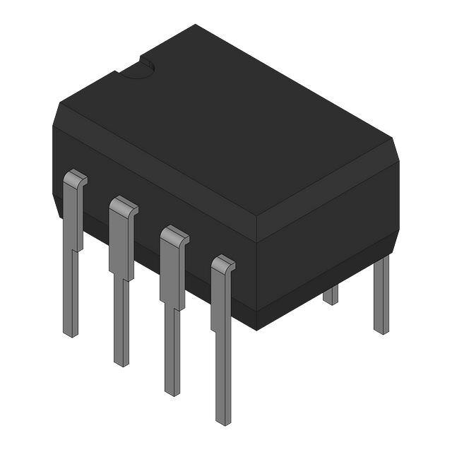
Figure 1. 8-Lead PDIP (N) and 8-Lead CERDIP (Q) Packages
NC 1
16 NC
OFFSETNULL 2
15 OFFSETNULL
–IN 3
14 V+
NC 4
13 NC
+IN 5
V– 7
12 OUTPUT
AD844
11 TZ
10 NC
TOP VIEW
NC 8 (Not to Scale) 9 NC
Flash ADC input amplifiers
High speed current DAC interfaces
Video buffers and cable drivers
Pulse amplifiers
NC = NO CONNECT
00897-002
NC 6
APPLICATIONS
Figure 2. 16-Lead SOIC (R) Package
GENERAL DESCRIPTION
The AD844 is a high speed monolithic operational amplifier
fabricated using the Analog Devices, Inc., junction isolated
complementary bipolar (CB) process. It combines high bandwidth and very fast large signal response with excellent dc
performance. Although optimized for use in current-to-voltage
applications and as an inverting mode amplifier, it is also suitable
for use in many noninverting applications.
The AD844 can be used in place of traditional op amps, but its
current feedback architecture results in much better ac performance, high linearity, and an exceptionally clean pulse response.
This type of op amp provides a closed-loop bandwidth that is
determined primarily by the feedback resistor and is almost
independent of the closed-loop gain. The AD844 is free from
the slew rate limitations inherent in traditional op amps and
other current-feedback op amps. Peak output rate of change can
be over 2000 V/μs for a full 20 V output step. Settling time is
typically 100 ns to 0.1%, and essentially independent of gain.
The AD844 can drive 50 Ω loads to ±2.5 V with low distortion
and is short-circuit protected to 80 mA.
The AD844 is available in four performance grades and three
package options. In the 16-lead SOIC (RW) package, the AD844J
is specified for the commercial temperature range of 0°C to 70°C.
Rev. G
AD844
–IN 2
00897-001
FEATURES
The AD844A and AD844B are specified for the industrial
temperature range of −40°C to +85°C and are available in the
CERDIP (Q) package. The AD844A is also available in an 8-lead
PDIP (N). The AD844S is specified over the military temperature
range of −55°C to +125°C. It is available in the 8-lead CERDIP
(Q) package. A and S grade chips and devices processed to
MIL-STD-883B, Rev. C are also available.
PRODUCT HIGHLIGHTS
1.
2.
3.
4.
5.
6.
The AD844 is a versatile, low cost component providing an
excellent combination of ac and dc performance.
It is essentially free from slew rate limitations. Rise and fall
times are essentially independent of output level.
The AD844 can be operated from ±4.5 V to ±18 V power
supplies and is capable of driving loads down to 50 Ω, as
well as driving very large capacitive loads using an external
network.
The offset voltage and input bias currents of the AD844 are
laser trimmed to minimize dc errors; VOS drift is typically 1
μV/°C and bias current drift is typically 9 nA/°C.
The AD844 exhibits excellent differential gain and
differential phase characteristics, making it suitable for a
variety of video applications with bandwidths up to 60 MHz.
The AD844 combines low distortion, low noise, and low
drift with wide bandwidth, making it outstanding as an
input amplifier for flash analog-to-digital converters (ADCs).
Document Feedback
Information furnished by Analog Devices is believed to be accurate and reliable. However, no
responsibility is assumed by Analog Devices for its use, nor for any infringements of patents or other
rights of third parties that may result from its use. Specifications subject to change without notice. No
license is granted by implication or otherwise under any patent or patent rights of Analog Devices.
Trademarks and registered trademarks are the property of their respective owners.
One Technology Way, P.O. Box 9106, Norwood, MA 02062-9106, U.S.A.
Tel: 781.329.4700
©1989-2017 Analog Devices, Inc. All rights reserved.
Technical Support
www.analog.com
�AD844
Data Sheet
TABLE OF CONTENTS
Features .............................................................................................. 1
Response as an Inverting Amplifier ......................................... 12
Applications ....................................................................................... 1
Response as an I-V Converter .................................................. 13
Functional Block Diagrams ............................................................. 1
Circuit Description of the AD844 ............................................ 13
General Description ......................................................................... 1
Response as a Noninverting Amplifier.................................... 14
Product Highlights ........................................................................... 1
Noninverting Gain of 100 ......................................................... 14
Revision History ............................................................................... 2
Using the AD844 ............................................................................ 15
Specifications..................................................................................... 3
Board Layout ............................................................................... 15
Absolute Maximum Ratings............................................................ 5
Input Impedance ........................................................................ 15
Metallization Photograph ............................................................ 5
Driving Large Capacitive Loads ............................................... 15
ESD Caution .................................................................................. 5
Settling Time ............................................................................... 15
Typical Performance Characteristics ............................................. 6
DC Error Calculation ................................................................ 16
Inverting Gain-of-1 AC Characteristics .................................... 8
Noise ............................................................................................ 16
Inverting Gain-of-10 AC Characteristics .................................. 9
Video Cable Driver Using ±5 V Supplies ................................ 16
Inverting Gain-of-10 Pulse Response ...................................... 10
High Speed DAC Buffer ............................................................ 17
Noninverting Gain-of-10 AC Characteristics ........................ 11
20 MHz Variable Gain Amplifier ............................................. 17
Understanding the AD844 ............................................................ 12
Outline Dimensions ....................................................................... 19
Open-Loop Behavior ................................................................. 12
Ordering Guide .......................................................................... 20
REVISION HISTORY
5/2017—Rev. F to Rev. G
Change to Figure 32 ....................................................................... 14
2/2009—Rev. E to Rev F
Updated Format .................................................................. Universal
Changes to Features Section............................................................ 1
Changes to Differential Phase Error Parameter, Table 1 ............. 3
Changes to Figure 13 ........................................................................ 8
Changes to Figure 18 ........................................................................ 9
Changes to Figure 23 and Figure 24 ............................................. 11
Changes to Figure 42 and High Speed DAC Buffer Section ..... 17
Updated Outline Dimensions ....................................................... 19
Changes to Ordering Guide .......................................................... 20
1/2003—Rev. D to Rev. E
Updated Features ...............................................................................1
Edit to TPC 18 ...................................................................................7
Edits to Figure 13 and Figure 14................................................... 13
Updated Outline Dimensions ....................................................... 15
11/2001—Rev. C to Rev. D
Edits to Specifications ......................................................................2
Edits to Absolute Maximum Ratings ..............................................3
Edits to Ordering Guide ...................................................................3
Rev. G | Page 2 of 20
�Data Sheet
AD844
SPECIFICATIONS
TA = 25°C and VS = ±15 V dc, unless otherwise noted.
Table 1.
Parameter
INPUT OFFSET VOLTAGE1
TMIN to TMAX
vs. Temperature
vs. Supply
Initial
TMIN to TMAX
vs. Common Mode
Initial
TMIN to TMAX
INPUT BIAS CURRENT
Negative Input Bias Current1
TMIN to TMAX
vs. Temperature
vs. Supply
Initial
TMIN to TMAX
vs. Common Mode
Initial
TMIN to TMAX
Positive Input Bias Current1
TMIN to TMAX
vs. Temperature
vs. Supply
Initial
TMIN to TMAX
vs. Common Mode
Initial
TMIN to TMAX
INPUT CHARACTERISTICS
Input Resistance
Negative Input
Positive Input
Input Capacitance
Negative Input
Positive Input
Input Common-Mode Voltage
Range
INPUT VOLTAGE NOISE
INPUT CURRENT NOISE
Negative Input
Positive Input
OPEN-LOOP TRANSRESISTANCE
TMIN to TMAX
Transcapacitance
DIFFERENTIAL GAIN ERROR2
DIFFERENTIAL PHASE ERROR2
Conditions
AD844J/AD844A
Min
Typ
Max
50
300
75
500
1
Min
AD844B
Typ
50
75
1
Max
150
200
5
Min
AD844S
Typ
50
125
1
Max
300
500
5
Unit
μV
μV
μV/°C
5 V to 18 V
4
4
20
4
4
10
10
4
4
20
20
μV/V
μV/V
10
10
35
10
10
20
20
10
10
35
35
μV/V
μV/V
200
800
9
450
1500
150
750
9
250
1100
15
200
1900
20
450
2500
30
nA
nA
nA/°C
175
220
250
175
220
200
240
175
220
250
300
nA/V
nA/V
90
110
150
350
3
160
90
110
100
300
3
110
150
200
500
7
90
120
100
800
7
160
200
400
1300
15
nA/V
nA/V
nA
nA
nA/°C
VCM = ±10 V
5 V to 18 V
VCM = ±10 V
400
700
5 V to 18 V
80
100
150
80
100
100
120
80
120
150
200
nA/V
nA/V
90
130
150
90
130
120
190
90
140
150
200
nA/V
nA/V
50
10
65
50
10
65
50
10
65
Ω
MΩ
VCM = ±10 V
7
7
2
2
±10
7
2
2
±10
2
2
pF
pF
V
±10
f ≥ 1 kHz
2
2
2
nV/√Hz
f ≥ 1 kHz
f ≥ 1 kHz
VOUT = ±10 V
RL = 500 Ω
10
12
10
12
10
12
pV/√Hz
pV/√Hz
3.0
1.6
4.5
0.03
0.16
MΩ
MΩ
pF
%
Degree
f = 4.4 MHz
f = 4.4 MHz
2.2
1.3
3.0
2.0
4.5
0.03
0.16
Rev. G | Page 3 of 20
2.8
1.6
3.0
2.0
4.5
0.03
0.16
2.2
1.3
�AD844
Parameter
FREQUENCY RESPONSE
Small Signal Bandwidth3, 4
Gain = −1
Gain = −10
TOTAL HARMONIC DISTORTION
SETTLING TIME
10 V Output Step
Gain = −1, to 0.1%5
Gain = −10, to 0.1%6
2 V Output Step
Gain = −1, to 0.1%5
Gain = −10, to 0.1%6
OUTPUT SLEW RATE
FULL POWER BANDWIDTH
VOUT = 20 V p-p5
VOUT = 2 V p-p5
OUTPUT CHARACTERISTICS
Voltage
Short-Circuit Current
TMIN to T MAX
Output Resistance
POWER SUPPLY
Operating Range
Quiescent Current
TMIN to TMAX
Data Sheet
Conditions
AD844J/AD844A
Min
Typ
Max
f = 100 kHz,
2 V rms5
Min
AD844B
Typ
Max
Min
AD844S
Typ
Max
Unit
60
33
0.005
60
33
0.005
60
33
0.005
MHz
MHz
%
100
100
100
100
100
100
ns
ns
110
100
2000
110
100
2000
110
100
2000
ns
ns
V/μs
20
20
MHz
MHz
±11
80
60
15
V
mA
mA
Ω
±15 V supplies
±5 V supplies
Overdriven
input
THD = 3%
VS = ±15 V
VS = ±5 V
1200
RL = 500 Ω
±10
1200
20
20
Open loop
20
20
±11
80
60
15
±4.5
6.5
7.5
1200
±10
±18
7.5
8.5
1
±4.5
Rated performance after a 5 minute warm-up at TA = 25°C.
Input signal 285 mV p-p carrier (40 IRE) riding on 0 mV to 642 mV (90 IRE) ramp. RL = 100 Ω; R1, R2 = 300 Ω.
3
For gain = −1, input signal = 0 dBm, CL = 10 pF, RL = 500 Ω, R1 = 500 Ω, and R2 = 500 Ω in Figure 29.
4
For gain = −10, input signal = 0 dBm, CL =10 pF, RL = 500 Ω, R1 = 500 Ω, and R2 = 50 Ω in Figure 29.
5
CL = 10 pF, RL = 500 Ω, R1 = 1 kΩ, R2 = 1 kΩ in Figure 29.
6
CL = 10 pF, RL = 500 Ω, R1 = 500 Ω, R2 = 50 Ω in Figure 29.
2
Rev. G | Page 4 of 20
±11
80
60
15
6.5
7.5
±10
±18
7.5
8.5
±4.5
6.5
7.5
±18
7.5
8.5
V
mA
mA
�Data Sheet
AD844
ABSOLUTE MAXIMUM RATINGS
METALLIZATION PHOTOGRAPH
Table 2.
1
Contact factory for latest dimensions.
Ratings
±18 V
1.1 W
Indefinite
±VS
6V
Dimensions shown in inches and (millimeters).
–IN
5 mA
10 mA
−65°C to +150°C
−65°C to +125°C
300°C
1000 V
NULL
+VS
0.076
(1.9)
28-lead PDIP package: θJA = 90°C/W.
8-lead CERDIP package: θJA = 110°C/W.
16-lead SOIC package: θJA = 100°C/W.
+IN
Stresses at or above those listed under Absolute Maximum
Ratings may cause permanent damage to the product. This is a
stress rating only; functional operation of the product at these
or any other conditions above those indicated in the operational
section of this specification is not implied. Operation beyond
the maximum operating conditions for extended periods may
affect product reliability.
NULL
–VS
TZ
0.095
(2.4)
SUBSTRATE CONNECTED TO +VS
Figure 3. Die Photograph
ESD CAUTION
Rev. G | Page 5 of 20
OUTPUT
00897-003
Parameter
Supply Voltage
Power Dissipation1
Output Short-Circuit Duration
Input Common-Mode Voltage
Differential Input Voltage
Inverting Input Current
Continuous
Transient
Storage Temperature Range (Q)
Storage Temperature Range (N, RW)
Lead Temperature (Soldering, 60 sec)
ESD Rating
�AD844
Data Sheet
TYPICAL PERFORMANCE CHARACTERISTICS
20
60
15
INPUT VOLTAGE (V)
70
50
40
0
5
10
15
20
SUPPLY VOLTAGE (±V)
0
0
5
10
15
20
SUPPLY VOLTAGE (±V)
Figure 4. −3 dB Bandwidth vs. Supply Voltage, R1 = R2 = 500 Ω
–60
10
00897-007
30
TA = 25°C
5
00897-004
–3dB BANDWIDTH (MHz)
TA = 25°C and VS = ±15 V, unless otherwise noted.
Figure 7. Noninverting Input Voltage Swing vs. Supply Voltage
20
1V rms
RL = 500Ω
TA = 25°C
HARMONIC DISTORTION (dB)
–70
15
OUTPUT VOLTAGE (V)
–80
–90
–100
–110
SECOND HARMONIC
10
5
10k
100k
INPUT FREQUENCY (Hz)
0
00897-005
1k
0
5
10
15
20
00897-008
THIRD HARMONIC
–130
100
140
00897-009
–120
SUPPLY VOLTAGE (±V)
Figure 8. Output Voltage Swing vs. Supply Voltage
Figure 5. Harmonic Distortion vs. Input Frequency, R1 = R2 = 1 kΩ
10
5
RL = ∞
9
SUPPLY CURRENT (mA)
RL = 500Ω
3
2
RL = 50Ω
0
–50
8
7
VS = ±15V
6
VS = ±5V
1
5
0
50
100
TEMPERATURE (°C)
Figure 6. Transresistance vs. Temperature
150
4
–60
00897-006
TRANSRESISTANCE (MΩ)
4
–40
–20
0
20
40
60
TEMPERATURE (-°C)
80
100
120
Figure 9. Quiescent Supply Current vs. Temperature and Supply Voltage
Rev. G | Page 6 of 20
�Data Sheet
AD844
40
2
VS = ±15V
1
–3dB BANDWIDTH (MHz)
IBP
0
–1
IBN
0
50
100
150
TEMPERATURE (°C)
Figure 10. Inverting Input Bias Current (IBN) and Noninverting Input Bias
Current (IBP) vs. Temperature
0.1
10M
100M
00897-011
OUTPUT IMPEDANCE (Ω)
±5V SUPPLIES
1M
–20
0
20
40
60
80
100
120
140
Figure 12. –3 dB Bandwidth vs. Temperature, Gain = −1, R1 = R2 = 1 kΩ
1
FREQUENCY (Hz)
–40
TEMPERATURE (-°C)
10
100k
VS = ±5V
20
10
–60
100
0.01
10k
25
15
00897-010
–2
–50
30
00897-012
INPUT BIAS CURRENT (µA)
35
Figure 11. Output Impedance vs. Frequency, Gain = −1, R1 = R2 = 1 kΩ
Rev. G | Page 7 of 20
�AD844
Data Sheet
INVERTING GAIN-OF-1 AC CHARACTERISTICS
+VS
0.22µF
5V
4.7Ω
100
R1
–IN
R2
90
–
AD844
OUTPUT
+
CL
RL
10
0.22µF
00897-013
–VS
20ns
00897-016
0
4.7Ω
Figure 16. Large Signal Pulse Response, Gain = −1, R1 = R2 = 1 kΩ
Figure 13. Inverting Amplifier, Gain of −1 (R1 = R2)
6
500nV
R1 = R2 = 500Ω
100
0
90
GAIN (dB)
R1 = R2 = 1kΩ
–6
–12
10
–18
1M
10M
100M
FREQUENCY (Hz)
00897-014
20ns
–24
100k
Figure 14. Gain vs. Frequency for Gain = −1, RL = 500 Ω, CL = 0 pF
–180
R1 = R2 = 500Ω
–240
–270
R1 = R2 = 1kΩ
–300
–330
0
25
50
FREQUENCY (MHz)
00897-015
PHASE (Degrees)
–210
Figure 15. Phase vs. Frequency for Gain = −1, RL = 500 Ω, CL = 0 pF
Rev. G | Page 8 of 20
00897-017
0
Figure 17. Small Signal Pulse Response, Gain = −1, R1 = R2 = 1 kΩ
�Data Sheet
AD844
INVERTING GAIN-OF-10 AC CHARACTERISTICS
+VS
RL = 500Ω
20
500Ω
–
AD844
GAIN (dB)
OUTPUT
+
RL
RL = 50Ω
14
8
CL
0.22µF
–VS
00897-018
2
4.7Ω
–4
100k
1M
10M
100M
FREQUENCY (Hz)
00897-019
50Ω
Figure 19. Gain vs. Frequency, Gain = −10
Figure 18. Gain of −10 Amplifier
–180
–210
RL = 50Ω
PHASE (Degrees)
–IN
RL = 500Ω
–240
–270
–300
–330
0
25
FREQUENCY (MHz)
Figure 20. Phase vs. Frequency, Gain = −10
Rev. G | Page 9 of 20
50
00897-020
0.22µF
26
4.7Ω
�AD844
Data Sheet
INVERTING GAIN-OF-10 PULSE RESPONSE
100
90
90
10
10
0
0
20ns
00897-021
100
20ns
Figure 21. Large Signal Pulse Response, Gain = –10, RL = 500 Ω
00897-022
500nV
5V
Figure 22. Small Signal Pulse Response, Gain = −10, RL = 500 Ω
Rev. G | Page 10 of 20
�Data Sheet
AD844
NONINVERTING GAIN-OF-10 AC CHARACTERISTICS
+VS
4.7Ω
2V
0.22µF
100ns
100
450Ω
50Ω
90
–
OUTPUT
AD844
+
–IN
0.22µF
RL
CL
00897-023
4.7Ω
10
0
00897-026
–VS
Figure 26. Noninverting Amplifier Large Signal Pulse Response, Gain = +10,
RL = 500 Ω
Figure 23. Noninverting Gain of +10 Amplifier
26
200nV
20
GAIN (dB)
RL = 50Ω
50ns
100
RL = 500Ω
90
14
8
2
10
1M
10M
100M
FREQUENCY (Hz)
Figure 24. Gain vs. Frequency, Gain = +10
Figure 27. Small Signal Pulse Response, Gain = +10, RL = 500 Ω
–180
–210
RL = 500Ω
–240
–270
–300
–330
0
25
FREQUENCY (MHz)
50
00897-025
PHASE (Degrees)
RL = 50Ω
00897-027
–4
100k
00897-024
0
Figure 25. Phase vs. Frequency, Gain = +10
Rev. G | Page 11 of 20
�AD844
Data Sheet
UNDERSTANDING THE AD844
The AD844 can be used in ways similar to a conventional op
amp while providing performance advantages in wideband
applications. However, there are important differences in the
internal structure that need to be understood to optimize the
performance of the AD844 op amp.
RESPONSE AS AN INVERTING AMPLIFIER
Figure 29 shows the connections for an inverting amplifier.
Unlike a conventional amplifier, the transient response and the
small signal bandwidth are determined primarily by the value of
the external feedback resistor, R1, rather than by the ratio of
R1/R2 as is customarily the case in an op amp application. This
is a direct result of the low impedance at the inverting input. As
with conventional op amps, the closed-loop gain is −R1/R2.
OPEN-LOOP BEHAVIOR
Figure 28 shows a current feedback amplifier reduced to essentials. Sources of fixed dc errors, such as the inverting node bias
current and the offset voltage, are excluded from this model.
The most important parameter limiting the dc gain is the
transresistance, Rt, which is ideally infinite. A finite value of Rt
is analogous to the finite open-loop voltage gain in a conventional
op amp.
The closed-loop transresistance is the parallel sum of R1 and Rt.
Because R1 is generally in the range of 500 Ω to 2 kΩ and Rt is
about 3 MΩ, the closed-loop transresistance is only 0.02% to
0.07% lower than R1. This small error is often less than the
resistor tolerance.
+1
IIN
Rt
Ct
+1
IIN
00897-028
RIN
Figure 28. Equivalent Schematic
The important parameters defining ac behavior are the
transcapacitance, Ct, and the external feedback resistor (not
shown). The time constant formed by these components is
analogous to the dominant pole of a conventional op amp and
thus cannot be reduced below a critical value if the closed-loop
system is to be stable. In practice, Ct is held to as low a value as
possible (typically 4.5 pF) so that the feedback resistor can be
maximized while maintaining a fast response. The finite RIN
also affects the closed-loop response in some applications.
When R1 is fairly large (above 5 kΩ) but still much less than Rt,
the closed-loop HF response is dominated by the time constant
R1 Ct. Under such conditions, the AD844 is overdamped and
provides only a fraction of its bandwidth potential. Because of
the absence of slew rate limitations under these conditions, the
circuit exhibits a simple single-pole response even under large
signal conditions.
In Figure 29, R3 is used to properly terminate the input if desired.
R3 in parallel with R2 gives the terminated resistance. As R1 is
lowered, the signal bandwidth increases, but the time constant
R1 Ct becomes comparable to higher order poles in the closedloop response. Therefore, the closed-loop response becomes
complex, and the pulse response shows overshoot. When R2
is much larger than the input resistance, RIN, at Pin 2, most of
the feedback current in R1 is delivered to this input, but as R2
becomes comparable to RIN, less of the feedback is absorbed at
Pin 2, resulting in a more heavily damped response. Consequently,
for low values of R2, it is possible to lower R1 without causing
instability in the closed-loop response. Table 3 lists combinations
of R1 and R2 and the resulting frequency response for the circuit
of Figure 29. Figure 16 shows the very clean and fast ±10 V
pulse response of the AD844.
The open-loop ac gain is also best understood in terms of the
transimpedance rather than as an open-loop voltage gain. The
open-loop pole is formed by Rt in parallel with Ct. Because Ct is
typically 4.5 pF, the open-loop corner frequency occurs at about
12 kHz. However, this parameter is of little value in determining
the closed-loop response.
Rev. G | Page 12 of 20
R1
VIN
R3
OPTIONAL
R2
AD844
VOUT
RL
CL
00897-029
The current applied to the inverting input node is replicated by
the current conveyor to flow in Resistor Rt. The voltage developed
across Rt is buffered by the unity gain voltage follower. Voltage
gain is the ratio Rt/RIN. With typical values of Rt = 3 MΩ and
RIN = 50 Ω, the voltage gain is about 60,000. The open-loop
current gain, another measure of gain that is determined by the
beta product of the transistors in the voltage follower stage (see
Figure 31), is typically 40,000.
Figure 29. Inverting Amplifier
�Data Sheet
AD844
R1
Table 3. Gain vs. Bandwidth
R1
1 kΩ
500 Ω
2 kΩ
1 kΩ
5 kΩ
500 Ω
1 kΩ
500 Ω
1 kΩ
5 kΩ
R2
1 kΩ
500 Ω
1 kΩ
500 Ω
1 kΩ
100 Ω
100 Ω
50 Ω
50 Ω
50 Ω
BW (MHz)
35
60
15
30
5.2
49
23
33
21
3.2
GBW (MHz)
35
60
30
60
26
245
230
330
420
320
RESPONSE AS AN I-V CONVERTER
The AD844 works well as the active element in an operational
current-to-voltage converter, used in conjunction with an
external scaling resistor, R1, in Figure 30. This analysis includes
the stray capacitance, CS, of the current source, which may be a
high speed DAC. Using a conventional op amp, this capacitance
forms a nuisance pole with R1 that destabilizes the closed-loop
response of the system. Most op amps are internally compensated
for the fastest response at unity gain, so the pole due to R1 and
CS reduces the already narrow phase margin of the system. For
example, if R1 is 2.5 kΩ, a CS of 15 pF places this pole at a
frequency of about 4 MHz, well within the response range of even
a medium speed operational amplifier. In a current feedback amp,
this nuisance pole is no longer determined by R1 but by the
input resistance, RIN. Because this is about 50 Ω for the AD844,
the same 15 pF forms a pole at 212 MHz and causes little
trouble. It can be shown that the response of this system is:
VOUT I sig
K R1
1 sTd 1 sTn
Rt
Rt R1
VOUT
RL
CL
Figure 30. Current-to-Voltage Converter
CIRCUIT DESCRIPTION OF THE AD844
A simplified schematic is shown in Figure 31. The AD844 differs
from a conventional op amp in that the signal inputs have
radically different impedance. The noninverting input (Pin 3)
presents the usual high impedance. The voltage on this input is
transferred to the inverting input (Pin 2) with a low offset voltage,
ensured by the close matching of like polarity transistors operating
under essentially identical bias conditions. Laser trimming nulls
the residual offset voltage, down to a few tens of microvolts. The
inverting input is the common emitter node of a complementary
pair of grounded base stages and behaves as a current summing
node. In an ideal current feedback op amp, the input resistance
is zero. In the AD844, it is about 50 Ω.
A current applied to the inverting input is transferred to a
complementary pair of unity-gain current mirrors that deliver
the same current to an internal node (Pin 5) at which the full
output voltage is generated. The unity-gain complementary
voltage follower then buffers this voltage and provides the load
driving power. This buffer is designed to drive low impedance
loads, such as terminated cables, and can deliver ±50 mA into a
50 Ω load while maintaining low distortion, even when operating
at supply voltages of only ±6 V. Current limiting (not shown)
ensures safe operation under short-circuited conditions.
7 +VS
where:
K is a factor very close to unity and represents the finite dc gain
of the amplifier.
Td is the dominant pole.
Tn is the nuisance pole.
K
AD844
CS
00897-030
Gain
−1
−1
−2
−2
−5
−5
−10
−10
−20
−100
ISIG
IB
+IN 3
2 –IN
TZ 5
6 OUTPUT
Td = KR1Ct
Using typical values of R1 = 1 kΩ and Rt = 3 MΩ, K = 0.9997; in
other words, the gain error is only 0.03%. This is much less than
the scaling error of virtually all DACs and can be absorbed, if
necessary, by the trim needed in a precise system.
In the AD844, Rt is fairly stable with temperature and supply
voltages, and consequently the effect of finite gain is negligible
unless high value feedback resistors are used. Because that
results in slower response times than are possible, the relatively
low value of Rt in the AD844 is rarely a significant source of error.
Rev. G | Page 13 of 20
4 –VS
Figure 31. Simplified Schematic
00897-031
IB
Tn = RINCS (assuming RIN


 工商网监
湘ICP备2023018690号
工商网监
湘ICP备2023018690号

