Octal LNA/VGA/AAF/ADC
and Crosspoint Switch
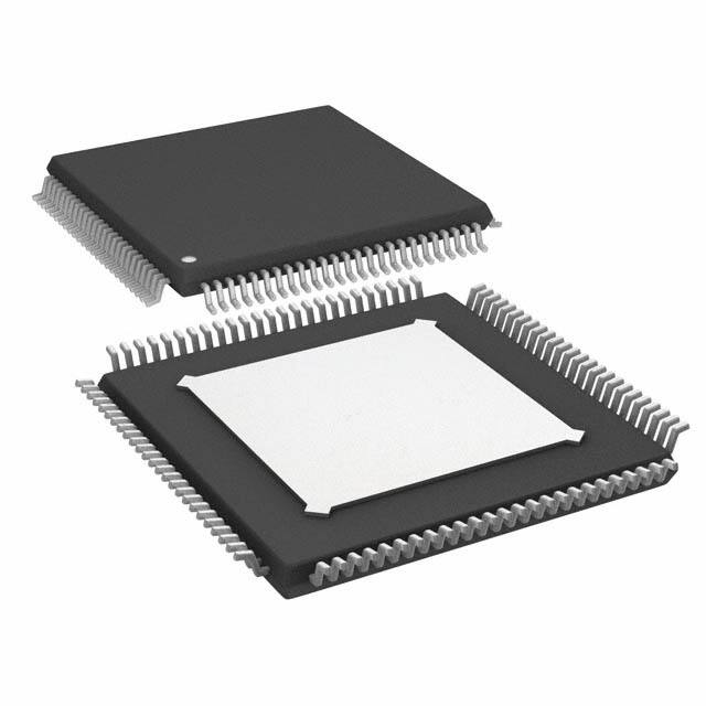
AD9271
Each channel features a variable gain range of 30 dB, a fully
differential signal path, an active input preamplifier termination, a
maximum gain of up to 40 dB, and an ADC with a conversion
rate of up to 50 MSPS. The channel is optimized for dynamic
performance and low power in applications where a small
package size is critical.
LO-C
LI-C
LG-C
LOSW-D
LO-D
LI-D
LG-D
LOSW-E
LO-E
LI-E
LG-E
LOSW-F
LO-F
LI-F
LG-F
LOSW-G
LO-G
LI-G
LG-G
LNA
VGA
AAF
LNA
VGA
AAF
LNA
VGA
AAF
LNA
VGA
AAF
LNA
VGA
AAF
LOSW-H
LO-H
LI-H
LG-H
LNA
VGA
AAF
SERIAL
LVDS
DOUTB+
DOUTB–
12-BIT
ADC
SERIAL
LVDS
DOUTC+
DOUTC–
12-BIT
ADC
SERIAL
LVDS
DOUTD+
DOUTD–
12-BIT
ADC
SERIAL
LVDS
DOUTE+
DOUTE–
12-BIT
ADC
SERIAL
LVDS
DOUTF+
DOUTF–
12-BIT
ADC
SERIAL
LVDS
DOUTG+
DOUTG–
12-BIT
ADC
SERIAL
LVDS
DOUTH+
DOUTH–
REFERENCE
SENSE
VREF
REFB
REFT
RBIAS
SWITCH
ARRAY
DATA
RATE
MULTIPLIER
LOSW-C
12-BIT
ADC
CLK+
CLK–
AAF
DOUTA+
DOUTA–
SDIO
VGA
SERIAL
LVDS
SERIAL
PORT
INTERFACE
LNA
12-BIT
ADC
CSB
SCLK
AAF
LOSW-B
LO-B
LI-B
LG-B
DRVDD
PDWN
STBY
VGA
FCO+
FCO–
DCO+
DCO–
06304-001
The AD9271 is designed for low cost, low power, small size,
and ease of use. It contains eight channels of a variable gain amplifier (VGA) with low noise preamplifier (LNA); an antialiasing
filter (AAF); and a 12-bit, 10 MSPS to 50 MSPS analog-to-digital
converter (ADC).
LNA
GAIN–
GENERAL DESCRIPTION
AD9271
GAIN+
Medical imaging/ultrasound
Automotive radar
LOSW-A
LO-A
LI-A
LG-A
CWVDD
APPLICATIONS
FUNCTIONAL BLOCK DIAGRAM
CWD[5:0]+/–
8 channels of LNA, VGA, AAF, and ADC
Low noise preamplifier (LNA)
Input-referred noise = 1.1 nV/√Hz @ 5 MHz typical,
gain = 18 dB
SPI-programmable gain = 14 dB/15.6 dB/18 dB
Single-ended input; VIN maximum = 400 mV p-p/
333 mV p-p/250 mV p-p
Dual-mode active input impedance matching
Bandwidth (BW) > 70 MHz
Full-scale (FS) output = 2 V p-p differential
Variable gain amplifier (VGA)
Gain range = −6 dB to +24 dB
Linear-in-dB gain control
Antialiasing filter (AAF)
3rd-order Butterworth cutoff
Programmable from 8 MHz to 18 MHz
Analog-to-digital converter (ADC)
12 bits at 10 MSPS to 50 MSPS
SNR = 70 dB
SFDR = 80 dB
Serial LVDS (ANSI-644, IEEE 1596.3 reduced range link)
Data and frame clock outputs
Includes crosspoint switch to support
continuous wave (CW) Doppler
Low power, 150 mW per channel at 12 bits/40 MSPS (TGC)
90 mW per channel in CW Doppler
Single 1.8 V supply (3.3 V supply for CW Doppler output bias)
Flexible power-down modes
Overload recovery in 40dB
06304-097
MAXIMUM GAIN
LNA INPUT-REFERRED
NOISE FLOOR
(5.4µV rms) @ AAF BW = 15MHz
LNA + VGA NOISE = 1.4nV/ Hz
Figure 48. Gain Requirements of TGC for a 12-Bit, 40 MSPS ADC
In summary, the maximum gain required is determined by
(ADC Noise Floor/VGA Input Noise Floor) + Margin =
20 log(224/5.4) + 8 dB = 40.3 dB
The minimum gain required is determined by
(ADC Input FS/VGA Input FS) + Margin =
20 log(2/0.333) – 5 dB = 10.6 dB
Therefore, a 12-bit, 40 MSPS ADC with 15 MHz of bandwidth
should suffice in achieving the dynamic range required for most
of today’s ultrasound systems.
Table 8. Channel Gain Distribution
Section
LNA
Attenuator
VGA Amp
Filter
ADC
Total
Nominal Gain (dB)
14/15.6/18
0 to −30
24
0
0
8.4 to 38.4/10 to 40/12.4 to 42.4
The linear-in-dB gain (law conformance) range of the TGC path
is 30 dB, extending from 10 dB to 40 dB. The slope of the gain
control interface is 31.6 dB/V, and the gain control range is 0 V
to 1 V as specified in Equation 3. Equation 4 is the expression
for channel gain.
VGAIN (V ) = (GAIN +) − (GAIN −) + 0.5
Gain (dB) = 31.6
dB
VGAIN + ICPT
V
(3)
(4)
where ICPT is the intercept point of the TGC gain.
In its default condition, the LNA has a gain of 15.6 dB (6×) and
the VGA gain is −6 dB if the voltage on the GAIN± pins is 0 V.
This gives rise to a total gain (or ICPT) of 10 dB through the
TGC path if the LNA input is unmatched, or of 4 dB if the LNA
is matched to 50 Ω (RFB = 200 Ω). If the voltage on the GAIN±
pins is 1 V, however, the VGA gain is 24 dB. This gives rise to a
total gain of 40 dB through the TGC path if the LNA input is
unmatched, or of 34 dB if the LNA input is matched.
Each LNA output is dc-coupled to a VGA input. The VGA consists
of an attenuator with a range of 30 dB followed by an amplifier
with 24 dB of gain for a net gain range of −6 dB to +24 dB. The
X-AMP gain-interpolation technique results in low gain error
and uniform bandwidth, and differential signal paths minimize
distortion.
At low gains, the VGA should limit the system noise performance (SNR); at high gains, the noise is defined by the source and
LNA. The maximum voltage swing is bound by the full-scale
peak-to-peak ADC input voltage (2 V p-p).
Both the LNA and VGA have limitations within each section of
the TGC path, depending on the voltage applied to the GAIN+ and
GAIN− pins. The LNA has three limitations, or full-scale settings,
depending on the gain selection applied through the SPI interface.
When a voltage of 0.2 V or less is applied to the GAIN± pins, the
LNA operates near the full-scale input range to maximize the
dynamic range of the ADC without clipping the signal. When
more than 0.2 V is applied to the GAIN± pins, the input signal to
the LNA must be lowered to keep it within the full-scale range
of the ADC (see Figure 49).
Rev. B | Page 25 of 60
�AD9271
0.450
slope is monotonic with respect to the control voltage and is
stable with variations in process, temperature, and supply.
LNA GAIN = 5x
The X-AMP inputs are part of a 24 dB gain feedback amplifier
that completes the VGA. Its bandwidth is about 70 MHz. The
input stage is designed to reduce feedthrough to the output and
to ensure excellent frequency response uniformity across the
gain setting.
0.350
LNA
GAIN = 6x
0.300
0.250
0.200
LNA GAIN = 8x
0.150
Gain Control
0.100
The gain control interface, GAIN±, is a differential input. The
VGA gain, VGAIN, is shown in Equation 3. VGAIN varies the gain
of all VGAs through the interpolator by selecting the appropriate
input stages connected to the input attenuator. The nominal
VGAIN range for 30 dB/V is 0 V to 1 V, with the best gain linearity
from about 0.1 V to 0.9 V, where the error is typically less than
±0.5 dB. For VGAIN voltages greater than 0.9 V and less than 0.1 V,
the error increases. The value of VGAIN can exceed the supply
voltage by 1 V without gain foldover.
06304-110
INPUT FULL-SCALE (V p-p)
0.400
0.050
0
0
0.1
0.2
0.3
0.4
0.5
0.6
0.7
0.8
0.9
1.0
VGAIN (V)
Figure 49. LNA/VGA Full-Scale Limitations
Variable Gain Amplifier
The differential X-AMP VGA provides precise input attenuation
and interpolation. It has a low input-referred noise of 4 nV/√Hz
and excellent gain linearity. A simplified block diagram is shown
in Figure 50.
There are two ways in which the GAIN+ and GAIN− pins can
be interfaced. Using a single-ended method, a Kelvin type of
connection to ground can be used as shown in Figure 51. For
driving multiple devices, it is preferable to use a differential
method, as shown in Figure 52. In either method, the GAIN+
and GAIN− pins should be dc-coupled and driven to accommodate a 1 V full-scale input.
GAIN
GAIN INTERPOLATOR
+
POSTAMP
gm
VIP
Gain control response time is less than 750 ns to settle within 10%
of the final value for a change from minimum to maximum gain.
3dB
VIN
AD9271
100Ω
0 TO 1V DC
GAIN+
50Ω
GAIN–
KELVIN
CONNECTION
0.01µF
Figure 50. Simplified VGA Schematic
Figure 51. Single-Ended GAIN± Pins Configuration
The input of the VGA is a 12-stage differential resistor ladder with
3.01 dB per tap. The resulting total gain range is 30 dB, which
allows for range loss at the endpoints. The effective input resistance
per side is 180 Ω nominally for a total differential resistance of
360 Ω. The ladder is driven by a fully differential input signal from
the LNA. LNA outputs are dc-coupled to avoid external decoupling
capacitors. The common-mode voltage of the attenuator and the
VGA is controlled by an amplifier that uses the same midsupply
voltage derived in the LNA, permitting dc coupling of the LNA
to the VGA without introducing large offsets due to commonmode differences. However, any offset from the LNA will be
amplified as the gain is increased, producing an exponentially
increasing VGA output offset.
The input stages of the X-AMP are distributed along the ladder,
and a biasing interpolator, controlled by the gain interface,
determines the input tap point. With overlapping bias currents,
signals from successive taps merge to provide a smooth
attenuation range from 0 dB to −30 dB. This circuit technique
results in linear-in-dB gain law conformance and low distortion
levels—only deviating ±0.5 dB or less from the ideal. The gain
499Ω
AD9271
GAIN+
100Ω
0.01µF
GAIN–
±0.25DC AT
0.5V CM
499Ω
26kΩ
±0.5V DC
AD8138
0.5V CM
50Ω
523Ω
100Ω
0.01µF
AVDD
10kΩ
±0.25DC AT
0.5V CM
499Ω
06304-098
POSTAMP
06304-109
–
06304-078
0.01µF
Figure 52. Differential GAIN± Pins Configuration
VGA Noise
In a typical application, a VGA compresses a wide dynamic
range input signal to within the input span of an ADC. The
input-referred noise of the LNA limits the minimum resolvable
input signal, whereas the output-referred noise, which depends
primarily on the VGA, limits the maximum instantaneous
dynamic range that can be processed at any one particular gain
control voltage. This latter limit is set in accordance with the
total noise floor of the ADC.
Output-referred noise as a function of VGAIN is shown in Figure 24
and Figure 25 for the short-circuit input conditions. The input
Rev. B | Page 26 of 60
�AD9271
noise voltage is simply equal to the output noise divided by the
measured gain at each point in the control range.
The output-referred noise is a flat 63 nV/√Hz over most of the
gain range, because it is dominated by the fixed output-referred
noise of the VGA. At the high end of the gain control range, the
noise of the LNA and source prevail. The input-referred noise
reaches its minimum value near the maximum gain control
voltage, where the input-referred contribution of the VGA is
miniscule.
At lower gains, the input-referred noise and, therefore, the noise
figure increases as the gain decreases. The instantaneous dynamic
range of the system is not lost, however, because the input capacity
increases as the input-referred noise increases. The contribution
of the ADC noise floor has the same dependence. The important
relationship is the magnitude of the VGA output noise floor
relative to that of the ADC.
Gain control noise is a concern in very low noise applications.
Thermal noise in the gain control interface can modulate the
channel gain. The resultant noise is proportional to the output
signal level and is usually evident only when a large signal is
present. The gain interface includes an on-chip noise filter, which
significantly reduces this effect at frequencies above 5 MHz. Care
should be taken to minimize noise impinging at the GAIN±
input. An external RC filter can be used to remove VGAIN source
noise. The filter bandwidth should be sufficient to accommodate
the desired control bandwidth.
Antialiasing Filter
The filter that the signal reaches prior to the ADC is used to
reject dc signals and to band limit the signal for antialiasing.
Figure 53 shows the architecture of the filter.
1C*
56pF/112pF
2kΩ
7.5C*
2kΩ
2kΩ
A third-order Butterworth low-pass filter is used to reduce
noise bandwidth and provide antialiasing for the ADC. The
filter uses on-chip tuning to trim the capacitors and in turn set
the desired cutoff frequency and reduce variations. The default
−3 dB cutoff is 1/3 the ADC sample clock rate. The cutoff can
be scaled to 0.7, 0.8, 0.9, 1, 1.1, 1.2, or 1.3 times this frequency
through the SPI. The cutoff can be set from 8 MHz to 18 MHz.
Tuning is normally off to avoid changing the capacitor settings
during critical times. The tuning circuit is enabled and disabled
through the SPI. Initializing the tuning of the filter must be
done after initial power-up and after reprogramming the filter
cutoff scaling or ADC sample rate. Occasional retuning during
an idle time is recommended to compensate for temperature drift.
ADC
The AD9271 architecture consists of a pipelined ADC divided
into three sections: a 4-bit first stage followed by eight 1.5-bit
stages and a 3-bit flash. Each stage provides sufficient overlap to
correct for flash errors in the preceding stages. The quantized
outputs from each stage are combined into a 12-bit result in the
digital correction logic. The pipelined architecture permits the
first stage to operate on a new input sample and the remaining
stages to operate on preceding samples. Sampling occurs on the
rising edge of the clock.
Each stage of the pipeline except for the last consists of a low
resolution flash ADC connected to a switched-capacitor DAC
and interstage residue amplifier (for example, a multiplying
digital-to-analog converter (MDAC)). The residue amplifier
magnifies the difference between the reconstructed DAC output
and the flash input for the next stage in the pipeline. One bit of
redundancy is used in each stage to facilitate digital correction
of flash errors. The last stage consists of a flash ADC.
4kΩ
2kΩ
The filter can be configured for dc coupling or to have a single
pole for high-pass filtering at either 700 kHz or 350 kHz
(programmed through the SPI). The high-pass pole, however, is
not tuned and can vary by ±30%.
2kΩ
The output staging block aligns the data, carries out error correction, and passes the data to the output buffers. The data is
then serialized and aligned to the frame and output clock.
6.5C*
2kΩ
1C*
4kΩ
*C = 0.5pF TO 3.1pF
06304-099
56pF/112pF
Figure 53. Simplified Filter Schematic
Rev. B | Page 27 of 60
�AD9271
For optimum performance, the AD9271 sample clock inputs
(CLK+ and CLK−) should be clocked with a differential signal.
This signal is typically ac-coupled into the CLK+ and CLK− pins
via a transformer or capacitors. These pins are biased internally
and require no additional bias.
Figure 54 shows the preferred method for clocking the AD9271.
A low jitter clock source, such as the Valpey Fisher oscillator
VFAC3-BHL-50MHz, is converted from single-ended to
differential using an RF transformer. The back-to-back Schottky
diodes across the secondary transformer limit clock excursions
into the AD9271 to approximately 0.8 V p-p differential. This
helps prevent the large voltage swings of the clock from feeding
through to other portions of the AD9271, and it preserves the
fast rise and fall times of the signal, which are critical to low
jitter performance.
In some applications, it is acceptable to drive the sample clock
inputs with a single-ended CMOS signal. In such applications,
CLK+ should be driven directly from a CMOS gate, and the
CLK− pin should be bypassed to ground with a 0.1 μF capacitor
in parallel with a 39 kΩ resistor (see Figure 57). Although the
CLK+ input circuit supply is AVDD (1.8 V), this input is
designed to withstand input voltages of up to 3.3 V, making the
selection of the drive logic voltage very flexible.
3.3V
VFAC3
OUT
EN
ADC
AD9271
CLK
0.1µF
CLK–
0.1µF
*50Ω RESISTOR IS OPTIONAL.
CLK+
OUT
EN
CLK–
CLK
50Ω *
OPTIONAL 0.1µF
100Ω
CMOS DRIVER
VFAC3
06304-050
SCHOTTKY
DIODES:
HSM2812
AD951x FAMILY
0.1µF
ADC
AD9271
0.1µF
CLK
0.1µF
If a low jitter clock is available, another option is to ac-couple a
differential PECL signal to the sample clock input pins as shown
in Figure 55. The AD951x family of clock drivers offers excellent
jitter performance.
3.3V
AD951x FAMILY
0.1µF
0.1µF
CLK+
CLK
0.1µF
100Ω
PECL DRIVER
0.1µF
240Ω
06304-051
240Ω
*50Ω
ADC
AD9271
CLK–
CLK
RESISTOR IS OPTIONAL.
Figure 55. Differential PECL Sample Clock
3.3V
50Ω *
AD951x FAMILY
0.1µF
0.1µF
CLK+
CLK
0.1µF
LVDS DRIVER
100Ω
0.1µF
CLK
*50Ω RESISTOR IS OPTIONAL.
Figure 56. Differential LVDS Sample Clock
ADC
AD9271
CLK–
06304-052
VFAC3
OUT
EN
0.1µF
CLK+
ADC
AD9271
CLK–
Figure 54. Transformer-Coupled Differential Clock
50Ω *
VFAC3
OUT
EN
39kΩ
3.3V
50Ω 100Ω
0.1µF
CLK+
Figure 57. Single-Ended 1.8 V CMOS Sample Clock
MINI-CIRCUITS
ADT1-1WT, 1:1Z
0.1µF
XFMR
VFAC3
OPTIONAL
0.1µF
100Ω
50Ω*
*50Ω RESISTOR IS OPTIONAL.
06304-054
EN OUT
CLK
CMOS DRIVER
3.3V
0.1µF
AD951x FAMILY
0.1µF
06304-053
CLOCK INPUT CONSIDERATIONS
Figure 58. Single-Ended 3.3 V CMOS Sample Clock
Clock Duty Cycle Considerations
Typical high speed ADCs use both clock edges to generate a
variety of internal timing signals. As a result, these ADCs may
be sensitive to the clock duty cycle. Commonly, a 5% tolerance is
required on the clock duty cycle to maintain dynamic performance
characteristics. The AD9271 contains a duty cycle stabilizer (DCS)
that retimes the nonsampling edge, providing an internal clock
signal with a nominal 50% duty cycle. This allows a wide range
of clock input duty cycles without affecting the performance of
the AD9271. When the DCS is on, noise and distortion performance are nearly flat for a wide range of duty cycles. However,
some applications may require the DCS function to be off. If so,
keep in mind that the dynamic range performance can be affected
when operated in this mode. See the Memory Map section for
more details on using this feature.
The duty cycle stabilizer uses a delay-locked loop (DLL) to
create the nonsampling edge. As a result, any changes to the
sampling frequency require approximately eight clock cycles
to allow the DLL to acquire and lock to the new rate.
Clock Jitter Considerations
High speed, high resolution ADCs are sensitive to the quality of the
clock input. The degradation in SNR at a given input frequency (fA)
due only to aperture jitter (tJ) can be calculated by
SNR Degradation = 20 × log 10[1/2 × π × fA × tJ]
Rev. B | Page 28 of 60
�AD9271
190
In this equation, the rms aperture jitter represents the root mean
square of all jitter sources, including the clock input, analog input
signal, and ADC aperture jitter. IF undersampling applications
are particularly sensitive to jitter (see Figure 59).
180
POWER/CHANNEL (mW)
170
The clock input should be treated as an analog signal in cases
where aperture jitter may affect the dynamic range of the AD9271.
Power supplies for clock drivers should be separated from the
ADC output driver supplies to avoid modulating the clock signal
with digital noise. Low jitter, crystal-controlled oscillators make
the best clock sources, such as the Valpey Fisher VFAC3 series.
If the clock is generated from another type of source (by gating,
dividing, or other methods), it should be retimed by the
original clock during the last step.
50MSPS SPEED GRADE
160
150
140
40MSPS SPEED GRADE
130
120
06304-031
25MSPS SPEED GRADE
110
100
0
10
20
30
40
50
SAMPLING FREQUENCY (MSPS)
Refer to the AN-501 Application Note and the AN-756
Application Note for more in-depth information about how
jitter performance relates to ADCs (visit www.analog.com).
Figure 61. Power per Channel vs. fSAMPLE for fIN = 7.5 MHz
By asserting the PDWN pin high, the AD9271 is placed into
power-down mode. In this state, the device typically dissipates
2 mW. During power-down, the LVDS output drivers are placed
into a high impedance state. The AD9271 returns to normal
operating mode when the PDWN pin is pulled low. This pin is
both 1.8 V and 3.3 V tolerant.
130
RMS CLOCK JITTER REQUIREMENT
120
110
16 BITS
90
14 BITS
SNR (dB)
100
80
12 BITS
70
10 BITS
60
50
0.125ps
0.25ps
0.5ps
1.0ps
2.0ps
8 BITS
40
1
10
100
ANALOG INPUT FREQUENCY (MHz)
06304-038
30
1000
Figure 59. Ideal SNR vs. Input Frequency and Jitter
Power Dissipation and Power-Down Mode
As shown in Figure 61, the power dissipated by the AD9271 is
proportional to its sample rate. The digital power dissipation
does not vary much because it is determined primarily by the
DRVDD supply and bias current of the LVDS output drivers
(Figure 60).
800
IAVDD , 50MSPS SPEED GRADE
700
IAVDD , 40MSPS SPEED GRADE
500
IAVDD , 25MSPS SPEED GRADE
400
300
200
100
06304-032
CURRENT (mA)
600
IDRVDD
0
0
10
20
30
40
50
SAMPLING FREQUENCY (MSPS)
Figure 60. Supply Current vs. fSAMPLE for fIN = 7.5 MHz
By asserting the STBY pin high, the AD9271 is placed into a
standby mode. In this state, the device typically dissipates
65 mW. During standby, the entire part is powered down except
the internal references. The LVDS output drivers are placed into
a high impedance state. This mode is well suited for applications
that require power savings because it allows the device to be
powered down when not in use and then quickly powered up.
The time to power the device back up is also greatly reduced. The
AD9271 returns to normal operating mode when the STBY pin
is pulled low. This pin is both 1.8 V and 3.3 V tolerant.
In power-down mode, low power dissipation is achieved by
shutting down the reference, reference buffer, PLL, and biasing
networks. The decoupling capacitors on REFT and REFB are
discharged when entering power-down mode and must be
recharged when returning to normal operation. As a result, the
wake-up time is related to the time spent in the power-down
mode: shorter cycles result in proportionally shorter wake-up
times. To restore the device to full operation, approximately
1 ms is required when using the recommended 0.1 μF and 4.7 μF
decoupling capacitors on the REFT and REFB pins and the
0.01 μF decoupling capacitors on the GAIN± pins. Most of this
time is dependent on the gain decoupling; higher value decoupling
capacitors on the GAIN± pins result in longer wake-up times.
There are a number of other power-down options available
when using the SPI port interface. The user can individually
power down each channel or put the entire device into standby
mode. This allows the user to keep the internal PLL powered up
when fast wake-up times are required. The wake-up time is
slightly dependent on gain. To achieve a 1 μs wake-up time
when the device is in standby mode, 0.5 V must be applied to
the GAIN± pins. See the Memory Map section for more details
on using these features.
Rev. B | Page 29 of 60
�AD9271
The AD9271 differential outputs conform to the ANSI-644 LVDS
standard on default power-up. This can be changed to a low power,
reduced signal option similar to the IEEE 1596.3 standard by using
the SDIO pin or via the SPI. This LVDS standard can further
reduce the overall power dissipation of the device by approximately
36 mW. See the SDIO Pin section or Table 15 for more
information.
The LVDS driver current is derived on chip and sets the output
current at each output equal to a nominal 3.5 mA. A 100 Ω differential termination resistor placed at the LVDS receiver inputs
results in a nominal 350 mV swing at the receiver.
The AD9271 LVDS outputs facilitate interfacing with LVDS
receivers in custom ASICs and FPGAs that have LVDS capability
for superior switching performance in noisy environments.
Single point-to-point net topologies are recommended with a
100 Ω termination resistor placed as close to the receiver as
possible. No far-end receiver termination and poor differential
trace routing may result in timing errors. It is recommended
that the trace length be no longer than 24 inches and that the
differential output traces be kept close together and at equal
lengths. An example of the FCO, DCO, and data stream with
proper trace length and position can be found in Figure 62.
Additional SPI options allow the user to further increase the
internal termination (and therefore increase the current) of all
eight outputs in order to drive longer trace lengths (see Figure 65).
Even though this produces sharper rise and fall times on the
data edges, is less prone to bit errors, and improves frequency
distribution (see Figure 65), the power dissipation of the DRVDD
supply increases when this option is used.
In cases that require increased driver strength to the DCO± and
FCO± outputs because of load mismatch, Register 0x15 allows
the user to double the drive strength. To do this, first set the
appropriate bit in Register 0x05. Note that this feature cannot
be used with Bit 4 and Bit 5 in Register 0x15 because these bits
take precedence over this feature. See the Memory Map section
for more details.
600
EYE: ALL BITS
400
EYE DIAGRAM VOLTAGE (V)
Digital Outputs and Timing
ULS: 2398/2398
200
100
0
–100
–200
–400
–600
–1.5ns
–1.0ns
–0.5ns
0ns
0.5ns
1.0ns
1.5ns
5.0ns/DIV
Figure 62. LVDS Output Timing Example in ANSI-644 Mode (Default)
An example of the LVDS output using the ANSI-644 standard
(default) data eye and a time interval error (TIE) jitter histogram
with trace lengths of less than 24 inches on regular FR-4 material
is shown in Figure 63. Figure 64 shows an example of the trace
lengths exceeding 24 inches on regular FR-4 material. Notice
that the TIE jitter histogram reflects the decrease of the data eye
opening as the edge deviates from the ideal position; therefore,
the user must determine if the waveforms meet the timing budget
of the design when the trace lengths exceed 24 inches.
20
15
10
5
0
–200ps
06304-035
CH1 500mV/DIV Ω
CH2 500mV/DIV Ω
CH3 500mV/DIV Ω
TIE JITTER HISTOGRAM (Hits)
06304-034
25
–100ps
0ps
100ps
200ps
Figure 63. Data Eye for LVDS Outputs in ANSI-644 Mode with Trace Lengths
of Less Than 24 Inches on Standard FR-4
Rev. B | Page 30 of 60
�AD9271
400
600
EYE: ALL BITS
300
EYE: ALL BITS
ULS: 2399/2399
ULS: 2396/2396
EYE DIAGRAM VOLTAGE (V)
EYE DIAGRAM VOLTAGE (V)
400
200
100
0
–100
–200
200
0
–200
–400
–300
–1.0ns
–0.5ns
0ns
0.5ns
1.0ns
–600
1.5ns
25
20
20
TIE JITTER HISTOGRAM (Hits)
25
15
10
5
0
–200ps
–100ps
0ps
100ps
–1.0ns
–0.5ns
0ns
0.5ns
1.0ns
1.5ns
15
10
5
0
–200ps
200ps
Figure 64. Data Eye for LVDS Outputs in ANSI-644 Mode with Trace Lengths
of Greater Than 24 Inches on Standard FR-4
–1.5ns
06304-037
–1.5ns
06304-036
TIE JITTER HISTOGRAM (Hits)
–400
–100ps
0ps
100ps
200ps
Figure 65. Data Eye for LVDS Outputs in ANSI-644 Mode with 100 Ω
Termination On and Trace Lengths of Greater Than 24 Inches on Standard FR-4
Rev. B | Page 31 of 60
�AD9271
The format of the output data is offset binary by default. An
example of the output coding format can be found in Table 9.
To change the output data format to twos complement, see the
Memory Map section.
Table 9. Digital Output Coding
Code
4095
2048
2047
0
(VIN+) − (VIN−),
Input Span = 2 V p-p (V)
+1.00
0.00
−0.000488
−1.00
Digital Output Offset Binary
(D11 ... D0)
1111 1111 1111
1000 0000 0000
0111 1111 1111
0000 0000 0000
Data from each ADC is serialized and provided on a separate
channel. The data rate for each serial stream is equal to 12 bits
times the sample clock rate, with a maximum of 600 Mbps
(12 bits × 50 MSPS = 600 Mbps). The lowest typical conversion
rate is 10 MSPS, but the PLL can be set up for encode rates as
low as 5 MSPS via the SPI if lower sample rates are required for
a specific application. See the Memory Map section for details
on enabling this feature.
Two output clocks are provided to assist in capturing data from
the AD9271. DCO± is used to clock the output data and is equal
to six times the sampling clock rate. Data is clocked out of the
AD9271 and must be captured on the rising and falling edges of
the DCO± that supports double data rate (DDR) capturing. The
frame clock output (FCO±) is used to signal the start of a new
output byte and is equal to the sampling clock rate. See the
timing diagram shown in Figure 2 for more information.
Table 10. Flexible Output Test Modes
Output Test Mode
Bit Sequence
0000
0001
Pattern Name
Off (default)
Midscale short
0010
+Full-scale short
0011
−Full-scale short
0100
Checkerboard
0101
0110
0111
PN sequence long 1
PN sequence short1
One-/zero-word toggle
1000
1001
User input
1-/0-bit toggle
1010
1× sync
1011
One bit high
1100
Mixed bit frequency
1
Digital Output Word 1
N/A
1000 0000 (8 bits)
10 0000 0000 (10 bits)
1000 0000 0000 (12 bits)
10 0000 0000 0000 (14 bits)
1111 1111 (8 bits)
11 1111 1111 (10 bits)
1111 1111 1111 (12 bits)
11 1111 1111 1111 (14 bits)
0000 0000 (8 bits)
00 0000 0000 (10 bits)
0000 0000 0000 (12 bits)
00 0000 0000 0000 (14 bits)
1010 1010 (8 bits)
10 1010 1010 (10 bits)
1010 1010 1010 (12 bits)
10 1010 1010 1010 (14 bits)
N/A
N/A
1111 1111 (8 bits)
11 1111 1111 (10 bits)
1111 1111 1111 (12 bits)
11 1111 1111 1111 (14 bits)
Register 0x19 and Register 0x1A
1010 1010 (8 bits)
10 1010 1010 (10 bits)
1010 1010 1010 (12 bits)
10 1010 1010 1010 (14 bits)
0000 1111 (8 bits)
00 0001 1111 (10 bits)
0000 0011 1111 (12 bits)
00 0000 0111 1111 (14 bits)
1000 0000 (8 bits)
10 0000 0000 (10 bits)
1000 0000 0000 (12 bits)
10 0000 0000 0000 (14 bits)
1010 0011 (8 bits)
10 0110 0011 (10 bits)
1010 0011 0011 (12 bits)
10 1000 0110 0111 (14 bits)
Digital Output Word 2
N/A
Same
Subject to Data
Format Select
N/A
Yes
Same
Yes
Same
Yes
0101 0101 (8 bits)
01 0101 0101 (10 bits)
0101 0101 0101 (12 bits)
01 0101 0101 0101 (14 bits)
N/A
N/A
0000 0000 (8 bits)
00 0000 0000 (10 bits)
0000 0000 0000 (12 bits)
00 0000 0000 0000 (14 bits)
Register 0x1B and Register 0x1C
N/A
No
N/A
No
N/A
No
N/A
No
Yes
Yes
No
No
No
All test mode options except PN sequence short and PN sequence long can support 8- to 14-bit word lengths in order to verify data capture to the receiver.
Rev. B | Page 32 of 60
�AD9271
When using the serial port interface (SPI), the DCO± phase can
be adjusted in 60° increments relative to the data edge. This
enables the user to refine system timing margins if required.
The default DCO± timing, as shown in Figure 2, is 90° relative
to the output data edge.
An 8-, 10-, and 14-bit serial stream can also be initiated from
the SPI. This allows the user to implement different serial streams
to test the device’s compatibility with lower and higher resolution
systems. When changing the resolution to an 8- or 10-bit serial
stream, the data stream is shortened. When using the 14-bit
option, the data stream stuffs two 0s at the end of the normal
14-bit serial data.
When using the SPI, all of the data outputs can also be inverted
from their nominal state. This is not to be confused with inverting
the serial stream to an LSB-first mode. In default mode, as shown
in Figure 2, the MSB is represented first in the data output serial
stream. However, this can be inverted so that the LSB is represented first in the data output serial stream (see Figure 3).
There are 12 digital output test pattern options available that
can be initiated through the SPI. This feature is useful when
validating receiver capture and timing. Refer to Table 10 for the
output bit sequencing options available. Some test patterns have
two serial sequential words and can be alternated in various
ways, depending on the test pattern chosen. It should be noted
that some patterns may not adhere to the data format select
option. In addition, customer user patterns can be assigned in
the 0x19, 0x1A, 0x1B, and 0x1C register addresses. All test mode
options except PN sequence short and PN sequence long can
support 8- to 14-bit word lengths in order to verify data capture
to the receiver.
SDIO Pin
This pin is required to operate the SPI. It has an internal 30 kΩ
pull-down resistor that pulls this pin low and is only 1.8 V
tolerant. If applications require that this pin be driven from a
3.3 V logic level, insert a 1 kΩ resistor in series with this pin to
limit the current.
SCLK Pin
This pin is required to operate the SPI port interface. It has an
internal 30 kΩ pull-down resistor that pulls this pin low and is
both 1.8 V and 3.3 V tolerant.
CSB Pin
This pin is required to operate the SPI port interface. It has an
internal 70 kΩ pull-down resistor that pulls this pin low and is
both 1.8 V and 3.3 V tolerant.
RBIAS Pin
To set the internal core bias current of the ADC, place a resistor
that is nominally equal to 10.0 kΩ between the RBIAS pin and
ground. Using a resistor of another value degrades the performance
of the device. Therefore, it is imperative that at least a 1% tolerance
on this resistor be used to achieve consistent performance.
Voltage Reference
A stable and accurate 0.5 V voltage reference is built into the
AD9271. This is gained up internally by a factor of 2, setting
VREF to 1.0 V, which results in a full-scale differential input
span of 2.0 V p-p for the ADC. VREF is set internally by default,
but the VREF pin can be driven externally with a 1.0 V reference to
achieve more accuracy. However, full-scale ranges below 2.0 V p-p
are not supported by this device.
The PN sequence short pattern produces a pseudorandom
bit sequence that repeats itself every 29 − 1 bits, or 511 bits. A
description of the PN sequence and how it is generated can be
found in Section 5.1 of the ITU-T 0.150 (05/96) standard. The
only difference is that the starting value is a specific value instead
of all 1s (see Table 11 for the initial values).
When applying the decoupling capacitors to the VREF, REFT,
and REFB pins, use ceramic low ESR capacitors. These capacitors
should be close to reference pins and on the same layer of the
PCB as the AD9271. The recommended capacitor values and
configurations for the AD9271 reference pin can be found in
Figure 66.
The PN sequence long pattern produces a pseudorandom bit
sequence that repeats itself every 223 − 1 bits, or 8,388,607 bits.
A description of the PN sequence and how it is generated can
be found in Section 5.6 of the ITU-T 0.150 (05/96) standard.
The only differences are that the starting value is a specific value
instead of all 1s and the AD9271 inverts the bit stream with
relation to the ITU standard (see Table 11 for the initial values).
Table 12. Reference Settings
Selected
Mode
External
Reference
Internal,
2 V p-p FSR
Table 11. PN Sequence
Sequence
PN Sequence Short
PN Sequence Long
Initial
Value
0x0df
0x29b80a
First Three Output Samples
(MSB First)
0xdf9, 0x353, 0x301
0x591, 0xfd7, 0xa3
Consult the Memory Map section for information on how to
change these additional digital output timing features through the
SPI.
Rev. B | Page 33 of 60
SENSE
Voltage
AVDD
Resulting
VREF (V)
N/A
AGND to 0.2 V
1.0
Resulting
Differential
Span (V p-p)
2 × external
reference
2.0
�AD9271
Internal Reference Operation
External Reference Operation
A comparator within the AD9271 detects the potential at the
SENSE pin and configures the reference. If SENSE is grounded,
the reference amplifier switch is connected to the internal
resistor divider (see Figure 66), setting VREF to 1 V.
The use of an external reference may be necessary to enhance
the gain accuracy of the ADC or to improve thermal drift characteristics. Figure 69 shows the typical drift characteristics of the
internal reference in 1 V mode.
The REFT and REFB pins establish their input span of the ADC
core from the reference configuration. The analog input fullscale range of the ADC equals twice the voltage at the reference
pin for either an internal or an external reference configuration.
When the SENSE pin is tied to AVDD, the internal reference is
disabled, allowing the use of an external reference. The external
reference is loaded with an equivalent 6 kΩ load. An internal
reference buffer generates the positive and negative full-scale
references, REFT and REFB, for the ADC core. Therefore, the
external reference must be limited to a nominal voltage of 1.0 V.
VIN+
VIN–
5
REFT
ADC
CORE
0.1µF
0.1µF
+
0
4.7µF
0.1µF
VREF
1µF
VREF ERROR (%)
REFB
0.1µF
0.5V
SELECT
LOGIC
SENSE
–5
–10
–15
–25
06304-017
06304-064
–20
0
0.5
Figure 66. Internal Reference Configuration
1.0
1.5
2.0
2.5
3.0
3.5
CURRENT LOAD (mA)
Figure 68. VREF Accuracy vs. Load, AD9271-50
0.02
VIN+
0
VIN–
REFT
+
–0.04
4.7µF
0.1µF
VREF
0.1µF*
0.5V
SELECT
LOGIC
–0.06
–0.08
–0.10
–0.12
–0.14
–0.16
SENSE
06304-015
AVDD
0.1µF
REFB
EXTERNAL
REFERENCE
1µF*
0.1µF
VREF ERROR (%)
ADC
CORE
–0.02
–0.18
–0.20
–40
–20
0
20
40
60
06304-065
TEMPERATURE (°C)
*OPTIONAL.
Figure 67. External Reference Operation
Rev. B | Page 34 of 60
Figure 69. Typical VREF Drift, AD9271-50
80
�AD9271
SERIAL PORT INTERFACE (SPI)
The AD9271 serial port interface allows the user to configure
the signal chain for specific functions or operations through a
structured register space provided inside the chip. This offers
the user added flexibility and customization depending on the
application. Addresses are accessed via the serial port and can
be written to or read from via the port. Memory is organized
into bytes that can be further divided into fields, as documented
in the Memory Map section. Detailed operational information
can be found in the Analog Devices, Inc., AN-877 Application
Note, Interfacing to High Speed ADCs via SPI.
In addition to the operation modes, the SPI port can be configured
to operate in different manners. For example, CSB can be tied
low to enable 2-wire mode. When CSB is tied low, SCLK and
SDIO are the only pins required for communication. Although
the device is synchronized during power-up, caution must be
exercised when using this mode to ensure that the serial port
remains synchronized with the CSB line. When operating in
2-wire mode, it is recommended that a 1-, 2-, or 3-byte transfer
be used exclusively. Without an active CSB line, streaming mode
can be entered but not exited.
Three pins define the serial port interface, or SPI: the SCLK,
SDIO, and CSB pins. The SCLK (serial clock) is used to
synchronize the read and write data presented to the device.
The SDIO (serial data input/output) is a dual-purpose pin that
allows data to be sent to and read from the device’s internal
memory map registers. The CSB (chip select bar) is an active
low control that enables or disables the read and write cycles
(see Table 13).
In addition to word length, the instruction phase determines if
the serial frame is a read or write operation, allowing the serial
port to be used to both program the chip and read the contents
of the on-chip memory. If the instruction is a readback operation,
performing a readback causes the serial data input/output (SDIO)
pin to change direction from an input to an output at the
appropriate point in the serial frame.
SDIO
CSB
Function
Serial Clock. The serial shift clock input. SCLK is used to
synchronize serial interface reads and writes.
Serial Data Input/Output. A dual-purpose pin. The typical
role for this pin is as an input or output, depending on
the instruction sent and the relative position in the
timing frame.
Chip Select Bar (Active Low). This control gates the read
and write cycles.
The falling edge of the CSB in conjunction with the rising edge of
the SCLK determines the start of the framing sequence. During an
instruction phase, a 16-bit instruction is transmitted, followed by
one or more data bytes, which is determined by Bit Field W0 and
Bit Field W1. An example of the serial timing and its definitions
can be found in Figure 71 and Table 14.
In normal operation, CSB is used to signal to the device that SPI
commands are to be received and processed. When CSB is brought
low, the device processes SCLK and SDIO to process instructions.
Normally, CSB remains low until the communication cycle is
complete. However, if connected to a slow device, CSB can be
brought high between bytes, allowing older microcontrollers
enough time to transfer data into shift registers. CSB can be stalled
when transferring one, two, or three bytes of data. When W0 and
W1 are set to 11, the device enters streaming mode and continues
to process data, either reading or writing, until the CSB is taken
high to end the communication cycle. This allows complete
memory transfers without having to provide additional instructtions. Regardless of the mode, if CSB is taken high in the middle
of any byte transfer, the SPI state machine is reset and the device
waits for a new instruction.
HARDWARE INTERFACE
The pins described in Table 13 constitute the physical interface
between the user’s programming device and the serial port of
the AD9271. The SCLK and CSB pins function as inputs when
using the SPI interface. The SDIO pin is bidirectional, functioning
as an input during write phases and as an output during readback.
In cases where multiple SDIO pins share a common connection,
care should be taken to ensure that proper VOH levels are met.
Figure 70 shows the number of SDIO pins that can be connected
together, assuming the same load as the AD9271 and the
resulting VOH level.
Rev. B | Page 35 of 60
1.800
1.795
1.790
1.785
1.780
1.775
1.770
1.765
1.760
1.755
1.750
1.745
1.740
1.735
1.730
1.725
1.720
1.715
0
10
20
30
40
50
60
70
80
90
NUMBER OF SDIO PINS CONNECTED TOGETHER
Figure 70. SDIO Pin Loading
100
06304-113
Pin
SCLK
VOH (V)
Table 13. Serial Port Pins
Data can be sent in MSB- or LSB-first mode. MSB-first mode
is the default at power-up and can be changed by adjusting the
configuration register. For more information about this and
other features, see the AN-877 Application Note, Interfacing to
High Speed ADCs via SPI.
�AD9271
This interface is flexible enough to be controlled by either serial
PROMs or PIC mirocontrollers. This provides the user an
alternative method, other than a full SPI controller, to program
the device (see the AN-812 Application Note).
tDS
tS
tHI
tCLK
tDH
tH
tLO
CSB
SCLK DON’T CARE
R/W
W1
W0
A12
A11
A10
A9
A8
A7
D5
D4
D3
D2
D1
D0
DON’T CARE
06304-068
SDIO DON’T CARE
DON’T CARE
Figure 71. Serial Timing Details
Table 14. Serial Timing Definitions
Parameter
tDS
tDH
tCLK
tS
tH
tHI
tLO
tEN_SDIO
Minimum Timing (ns)
5
2
40
5
2
16
16
10
tDIS_SDIO
10
Description
Setup time between the data and the rising edge of SCLK
Hold time between the data and the rising edge of SCLK
Period of the clock
Setup time between CSB and SCLK
Hold time between CSB and SCLK
Minimum period that SCLK should be in a logic high state
Minimum period that SCLK should be in a logic low state
Minimum time for the SDIO pin to switch from an input to an output relative to the SCLK
falling edge (not shown in Figure 71)
Minimum time for the SDIO pin to switch from an output to an input relative to the SCLK
rising edge (not shown in Figure 71)
Rev. B | Page 36 of 60
�AD9271
MEMORY MAP
READING THE MEMORY MAP TABLE
Each row in the memory map table has eight address locations.
The memory map is roughly divided into three sections: the
chip configuration register map (Address 0x00 to Address 0x02),
the device index and transfer register map (Address 0x04,
Address 0x05, and Address 0xFF), and the ADC functions
register map (Address 0x08 to Address 0x2D).
The leftmost column of the memory map indicates the register
address number; the default value is shown in the second
rightmost column. The Bit 7 (MSB) column is the start of the
default hexadecimal value given. For example, Address 0x09, the
clock register, has a default value of 0x01, meaning that Bit 7 =
0, Bit 6 = 0, Bit 5 = 0, Bit 4 = 0, Bit 3 = 0, Bit 2 = 0, Bit 1 = 0, and
Bit 0 = 1, or 0000 0001 in binary. This setting is the default for the
duty cycle stabilizer in the on condition. By writing 0 to Bit 0 of
this address followed by writing 0x01 in Register 0xFF (transfer
bit), the duty cycle stabilizer turns off. It is important to follow
each writing sequence with a transfer bit to update the SPI
registers. All registers, except Register 0x00, Register 0x02,
Register 0x04, Register 0x05, and Register 0xFF, are buffered with
a master-slave latch and require writing to the transfer bit. For
more information on this and other functions, consult the AN877 Application Note, Interfacing to High Speed ADCs via SPI.
RESERVED LOCATIONS
Undefined memory locations should not be written to except
when writing the default values suggested in this data sheet.
Addresses that have values marked as 0 should be considered
reserved and have 0 written into their registers during power-up.
DEFAULT VALUES
After a reset, critical registers are automatically loaded with
default values. These values are indicated in Table 15, where an
X refers to an undefined feature.
LOGIC LEVELS
An explanation of various registers follows: “Bit is set” is
synonymous with “bit is set to Logic 1” or “writing Logic 1 for
the bit.” Similarly, “clear a bit” is synonymous with “bit is set to
Logic 0” or “writing Logic 0 for the bit.”
Rev. B | Page 37 of 60
�AD9271
Table 15. Memory Map Register 1
Addr.
Bit 7
(Hex)
Register Name
(MSB)
Chip Configuration Registers
00
chip_port_config
0
01
chip_id
02
chip_grade
Bit 6
Bit 5
Bit 4
Bit 3
Bit 2
Bit 1
LSB first
1 = on
0 = off
(default)
Soft
reset
1 = on
0 = off
(default)
1
1
Soft
reset
1 = on
0 = off
(default)
LSB first
1 = on
0 = off
(default)
Default
Value
Notes/
Comments
0
0x18
The nibbles
should be
mirrored so
that LSB- or
MSB-first mode
is set correctly
regardless of
shift mode.
Default is
unique chip ID,
different for
each device.
This is a readonly register.
Child ID used
to differentiate
graded devices.
Chip ID Bits [7:0]
(AD9271 = 0x13), (default)
X
X
Child ID [5:4]
(identify device
variants of Chip ID)
00 = 50 MSPS
(default)
01 = 40 MSPS
10 = 25 MSPS
Read
only
X
X
X
X
0x00
Data
Channel
H
1 = on
(default)
0 = off
Data
Channel
D
1 = on
(default)
0 = off
X
Data
Channel
G
1 = on
(default)
0 = off
Data
Channel
F
1 = on
(default)
0 = off
Data
Channel
E
1 = on
(default)
0 = off
0x0F
Bits are set to
determine
which on-chip
device receives
the next write
command.
Data
Channel
C
1 = on
(default)
0 = off
X
Data
Channel
B
1 = on
(default)
0 = off
X
Data
Channel
A
1 = on
(default)
0 = off
SW
transfer
1 = on
0 = off
(default)
0x0F
Bits are set to
determine
which on-chip
device receives
the next write
command.
Synchronously
transfers data
from the
master shift
register to
the slave.
Internal power-down mode
000 = chip run (default)
001 = full power-down
010 = standby
011 = reset
100 = CW mode (TGC PDWN)
X
X
Duty cycle
stabilizer
1 = on
(default)
0 = off
Device Index and Transfer Registers
04
device_index_2
X
X
X
X
05
device_index_1
X
X
FF
device_update
X
X
Clock
Channel
DCO±
1 = on
0 = off
(default)
X
Clock
Channel
FCO±
1 = on
0 = off
(default)
X
ADC Functions Registers
08
modes
X
X
X
X
LNA
bypass
1 = on
0 = off
(default)
09
X
X
X
X
X
clock
Bit 0
(LSB)
Rev. B | Page 38 of 60
0x00
0x00
Determines
various generic
modes of chip
operation.
0x01
Turns the
internal duty
cycle stabilizer
on and off.
�AD9271
Addr.
(Hex)
0D
Register Name
test_io
Bit 7
(MSB)
Bit 6
User test mode
00 = off (default)
01 = on, single alternate
10 = on, single once
11 = on, alternate once
0F
flex_channel_input
10
flex_offset
11
flex_gain
Filter cutoff frequency control
0000 = 1.3 × 1/3 × fSAMPLE
0001 = 1.2 × 1/3 × fSAMPLE
0010 = 1.1 × 1/3 × fSAMPLE
0011 = 1.0 × 1/3 × fSAMPLE
0100 = 0.9 × 1/3 × fSAMPLE
0101 = 0.8 × 1/3 × fSAMPLE
0110 = 0.7 × 1/3 × fSAMPLE
X
X
6-bit LNA offset adjustment
011001 = 50 MSPS speed grade
011010 = 40 MSPS speed grade
011111 = 25 MSPS speed grade
X
X
X
X
X
14
output_mode
X
15
output_adjust
X
0 = LVDS
ANSI-644
(default)
1 = LVDS
low power,
(IEEE
1596.3
similar)
X
16
output_phase
X
X
Bit 5
Reset PN
long gen
1 = on
0 = off
(default)
X
Bit 4
Reset PN
short
gen
1 = on
0 = off
(default)
X
Bit 3
Bit 2
Bit 1
Bit 0
(LSB)
Output test mode—see Table 10
0000 = off (default)
0001 = midscale short
0010 = +FS short
0011 = −FS short
0100 = checkerboard output
0101 = PN sequence long
0110 = PN sequence short
0111 = one-/zero-word toggle
1000 = user input
1001 = 1-/0-bit toggle
1010 = 1× sync
1011 = one bit high
1100 = mixed bit frequency (format
determined by output_mode)
X
X
X
X
X
0x30
Antialiasing
filter cutoff
(global).
0x20
LNA force
offset
correction
(local).
LNA gain
adjustment
(global).
0x01
0x00
Configures the
outputs and
the format of
the data.
X
0x00
Determines
LVDS or other
output prop
erties. Primarily
functions to set
the LVDS span
and commonmode levels in
place of an
external
resistor.
On devices that
utilize global
clock divide,
determines
which phase of
the divider
output is used
to supply the
output clock.
Internal
latching
is unaffected.
Output
invert
1 = on
0 = off
(default)
Output driver
termination
00 = none (default)
01 = 200 Ω
10 = 100 Ω
11 = 100 Ω
X
X
X
0011 = output clock phase adjust
(0000 through 1010)
(Default: 180° relative to data edge)
0000 = 0° relative to data edge
0001 = 60° relative to data edge
0010 = 120° relative to data edge
0011 = 180° relative to data edge
0100 = 240° relative to data edge
0101 = 300° relative to data edge
0110 = 360° relative to data edge
0111 = 420° relative to data edge
1000 = 480° relative to data edge
1001 = 540° relative to data edge
1010 = 600° relative to data edge
1011 to 1111 = 660° relative to data edge
Rev. B | Page 39 of 60
Notes/
Comments
When this
register is set,
the test data is
placed on the
output pins in
place of normal
data. (Local,
expect for
PN sequence.)
LNA gain
00 = 5×
01 = 6×
10 = 8×
00 = offset binary
(default)
01 = twos
complement
X
X
Default
Value
0x00
DCO±
and
FCO±
2× drive
strength
1 = on
0 = off
(default)
0x03
�AD9271
Addr.
(Hex)
19
Register Name
user_patt1_lsb
Bit 7
(MSB)
B7
Bit 6
B6
Bit 5
B5
Bit 4
B4
Bit 3
B3
Bit 2
B2
Bit 1
B1
Bit 0
(LSB)
B0
Default
Value
0x00
1A
user_patt1_msb
B15
B14
B13
B12
B11
B10
B9
B8
0x00
1B
user_patt2_lsb
B7
B6
B5
B4
B3
B2
B1
B0
0x00
1C
user_patt2_msb
B15
B14
B13
B12
B11
B10
B9
B8
0x00
21
serial_control
LSB first
1 = on
0 = off
(default)
X
X
X
000 = 12 bits (default, normal bit
stream)
001 = 8 bits
010 = 10 bits
011 = 12 bits
100 = 14 bits
22
serial_ch_stat
X
X
X
X


 工商网监
湘ICP备2023018690号
工商网监
湘ICP备2023018690号
