FEATURES
FUNCTIONAL BLOCK DIAGRAM
Physical layer CAN transceiver
5 V operation on VCC
Complies with ISO 11898 standard
High speed data rates up to 1 Mbps
Short-circuit protection on CANH and CANL against shorts to
power/ground in 24 V systems
Unpowered nodes do not disturb the bus
Connect 110 or more nodes on the bus
Slope control for reduced EMI
Thermal shutdown protection
Low current standby mode
Industrial operating temperature range (−40°C to +125°C)
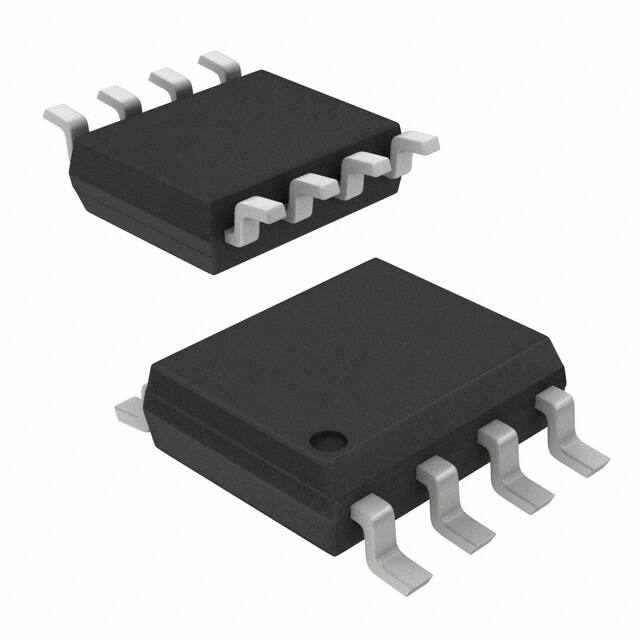
Available in 8-lead SOIC package
VCC
THERMAL
SHUTDOWN
TxD
RS
D
MODE
RxD
R
VREF
VOLTAGE
REFERENCE
CANH
CANL
ADM3051
APPLICATIONS
GND
CAN data buses
Industrial field networks
DeviceNet applications
CanOpen, CanKingdom
10029-001
Data Sheet
High Speed Industrial CAN Transceiver
with Bus Protection for 24 V Systems
ADM3051
Figure 1.
GENERAL DESCRIPTION
The ADM3051 is a controller area network (CAN) physical
layer transceiver allowing a protocol layer CAN controller to
access the physical layer bus. The ADM3051 complies with
the ISO 11898 standard. It is capable of running at data rates up
to 1 Mbps.
The device has current-limiting and thermal shutdown features
to protect against output short circuits and situations where the
bus may be shorted to ground or power terminals in 24 V bus
power systems. The part is fully specified over the industrial
temperature range of −40°C to +125°C and is available in an
8-lead SOIC package.
Rev. A
Three operating modes are available: high speed, slope control,
and standby. Pin 8 (RS) is used to select the operating mode.
The low current standby mode can be selected by applying a
logic high to RS.
The device can be set to operate with slope control to limit EMI
by connecting RS with a resistor to ground to modify the rise
and fall of slopes. This mode facilitates the use of unshielded
cables. Alternatively, disabling slope control by connecting RS
to ground allows high speed operation. Shielded cables or other
measures to control EMI are necessary in this mode.
Document Feedback
Information furnished by Analog Devices is believed to be accurate and reliable. However, no
responsibility is assumed by Analog Devices for its use, nor for any infringements of patents or other
rights of third parties that may result from its use. Specifications subject to change without notice. No
license is granted by implication or otherwise under any patent or patent rights of Analog Devices.
Trademarks and registered trademarks are the property of their respective owners.
One Technology Way, P.O. Box 9106, Norwood, MA 02062-9106, U.S.A.
Tel: 781.329.4700 ©2011–2016 Analog Devices, Inc. All rights reserved.
Technical Support
www.analog.com
�ADM3051
Data Sheet
TABLE OF CONTENTS
Features .............................................................................................. 1
Typical Performance Characteristics ..............................................7
Applications ....................................................................................... 1
Test Circuits and Switching Characteristics................................ 11
Functional Block Diagram .............................................................. 1
Circuit Description......................................................................... 13
General Description ......................................................................... 1
CAN Transceiver Operation ..................................................... 13
Revision History ............................................................................... 2
Operational Modes .................................................................... 13
Specifications..................................................................................... 3
Truth Tables................................................................................. 13
Timing Specifications .................................................................. 4
Thermal Shutdown .................................................................... 13
Absolute Maximum Ratings............................................................ 5
Applications Information .............................................................. 14
ESD Caution .................................................................................. 5
Outline Dimensions ....................................................................... 15
Pin Configuration and Function Descriptions ............................. 6
Ordering Guide .......................................................................... 15
REVISION HISTORY
5/2016—Rev.0 to Rev. A
Changes to Ordering Guide .......................................................... 15
9/2011—Revision 0: Initial Version
Rev. A | Page 2 of 16
�Data Sheet
ADM3051
SPECIFICATIONS
All voltages relative to ground (Pin 2); 4.5 V ≤ VCC ≤ 5.5 V. TA = −40°C to +125°C, RL = 60 Ω, IRS > −10 μA, unless otherwise noted. All
typical specifications are at TA = 25°C, VCC = 5 V, unless otherwise noted.
Table 1.
Parameter
SUPPLY CURRENT
Dominant State
Recessive State
Standby State
DRIVER
Logic Inputs
Input Voltage High
Input Voltage Low
CMOS Logic Input Current High
CMOS Logic Input Current Low
Differential Outputs
Recessive Bus Voltage
Off-State Output Leakage Current
CANH Output Voltage
CANL Output Voltage
Differential Output Voltage
Short-Circuit Current, CANH
Short-Circuit Current, CANL
RECEIVER
Differential Inputs
Voltage Recessive
Voltage Dominant
Input Voltage Hysteresis
CANH, CANL Input Resistance
Differential Input Resistance
Logic Outputs
Output Voltage High
Output Voltage Low
Short-Circuit Current
VOLTAGE REFERENCE
Reference Output Voltage
STANDBY/SLOPE CONTROL
Input Voltage for Standby Mode
Current for Slope Control Mode
Slope Control Mode Voltage
1
Symbol
ICC
Min
Typ
Max
Unit
Test Conditions/Comments
78
10
mA
mA
μA
VTxD = 1 V
VTxD = 4 V; RSLOPE = 47 kΩ
VRS = VCC, ITxD = IRxD = IVREF = 0 mA, TA < 90°C
275
VIH
VIL
IIH
IIL
0.7 VCC
−0.3
−200
−100
VCC + 0.3
+0.3 VCC
+30
−600
V
V
μA
μA
Output recessive
Output dominant
VTxD = 4 V
VTxD = 1 V
VCANH, VCANL
ILO
ILO
VCANH
VCANL
VOD
VOD
VOD
ISCCANH
ISCCANH
ISCCANL
2.0
−2
−10
3.0
0.5
1.5
1.5
−500
3.0
+2
+10
4.5
2.0
3.0
200
V
mA
mA
V
V
V
V
mV
mA
mA
mA
VTxD = 4 V, RL = ∞, see Figure 23
−2 V < (VCANL, VCANH) < 7 V
−5 V < (VCANL, VCANH) < 36 V
VTxD = 1 V, see Figure 23
VTxD = 1 V, see Figure 23
VTxD = 1 V, see Figure 23
VTxD = 1 V, RL = 45 Ω, see Figure 23
VTxD = 4 V, RL = ∞, see Figure 23
VCANH = −5 V
VCANH = −36 V
VCANL = 36 V
VIDR
−1.0
+0.5
V
−1.0
+0.4
V
0.9
5.0
V
1.0
5.0
V
5
20
25
100
mV
kΩ
kΩ
−2 V < VCANL, VCANH
很抱歉,暂时无法提供与“ADM3051CRZ”相匹配的价格&库存,您可以联系我们找货
免费人工找货