EVAL-ADM1293EBZ/EVAL-ADM1294EBZ User Guide
UG-722
One Technology Way • P.O. Box 9106 • Norwood, MA 02062-9106, U.S.A. • Tel: 781.329.4700 • Fax: 781.461.3113 • www.analog.com
Evaluating the ADM1293 and ADM1294 Digital Power Monitors
FEATURES
GENERAL DESCRIPTION
Full featured evaluation kits for ADM1293 and ADM1294
I²C/PMBus interface supports all product-related software
Supports bidirectional current emulation
Multiboard cascade support
This user guide describes how to use the ADM1293 and
ADM1294 evaluation kits. The kits provide all of the support
circuitry required to operate the ADM1293 and ADM1294 (in
their various modes and configurations, including multiple board
setups. The ADM1293 and ADM1294 data sheets, available at
www.analog.com, provide additional information, and should
be consulted when using the evaluation board. All documents
and software tools are available at www.analog.com/powermanagement.
EVALUATION KIT CONTENTS
8-way, 150 mm Micromatch ribbon cable
For EVAL-ADM1294EBZ only:
EVAL-ADM3260MEBZ
10-way, 150 mm Micromatch ribbon cable
ADDITIONAL EQUIPMENT NEEDED
USB-to-I²C dongle USB-SDP-CABLEZ
Power supply
Electronic load (optional)
Note that USB-SDP-CABLEZ is not included in the evaluation
kit and should be ordered separately. Only one dongle is
required in multiboard cascade setup. One device socket is
included in each kit.
RELATED DOCUMENTS
ADM1293 and ADM1294 data sheets
EVAL-ADM3260MEBZ user guide
SOFTWARE NEEDED
Hot swap and power monitoring evaluation software
available on the ADM1293 and ADM1294 product pages
EVALUATION BOARD PHOTOGRAPHS
Figure 2. ADM1294 Evaluation Board
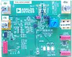
Figure 1. ADM1293 Evaluation Board
PLEASE SEE THE LAST PAGE FOR AN IMPORTANT
WARNING AND LEGAL TERMS AND CONDITIONS.
Rev. 0 | Page 1 of 10
�UG-722
EVAL-ADM1293EBZ/EVAL-ADM1294EBZ User Guide
TABLE OF CONTENTS
Features .............................................................................................. 1
Power Supply and Load Connection ..........................................3
Evaluation Kit Contents ................................................................... 1
Current Emulation ........................................................................4
Additional Equipment Needed ....................................................... 1
I2C/PMBus Interface .....................................................................4
Related Documents .......................................................................... 1
Multiple Board Setup ....................................................................5
Software Needed ............................................................................... 1
Add Isolation to the Communicaiton Interface ........................5
General Description ......................................................................... 1
Switch and LED Functions...........................................................5
Evaluation Board Photographs ....................................................... 1
Evaluation Board Schematics and Artwork ...................................6
Revision History ............................................................................... 2
Ordering Information .......................................................................8
Evaluation Board Hardware ............................................................ 3
Bill of Materials ..............................................................................8
REVISION HISTORY
9/14—Revision 0: Initial Version
Rev. 0 | Page 2 of 10
�EVAL-ADM1293EBZ/EVAL-ADM1294EBZ User Guide
UG-722
EVALUATION BOARD HARDWARE
keep the ADM1293 evaluation board supply above 5 V to keep
the devices such as on-board EEPROM powered. The on-board
EEPROM is used to store evaluation board information such as
board type, sense resistor, and divider values. The 0.5 mΩ sense
resistor allows maximum current sensing range around ±50 A
with 25 mV sense voltage range selected. Higher current
sensing range is possible by selecting higher sense voltage range,
but the user needs to be aware of the power dissipated in the
sense resistor.
The EVAL-ADM1293EBZ and EVAL-ADM1294EBZ boards are
designed for user evaluation of ADM1293 and ADM1294 digital
power monitor ICs.
Both evaluation kits are based on the same PCB design with
different component and configurations. The board is simple to
use, easy to probe, allows flexible wiring, and offers multiple
board cascadability.
POWER SUPPLY AND LOAD CONNECTION
The ADM1294 is designed for low side monitoring and with its
integrated shunt resistor it can be powered from high voltage
supplies with a wide voltage range. The ADM1294 evaluation
board is designed to be powered from a 48 V(or −48 V
depending on the referencing point) rail and monitors its
power. The 2 mΩ sense resistor allows maximum current
sensing range around ±12.5 A with 25 mV sense voltage range
selected.
The recommended power supply and load connection for the
evaluation boards is illustrated in Figure 3 and Figure 4.
The ADM1293 power monitor is designed to operate with
supply from 2.95 V to 20 V and can monitor supplies from 0 V
to 20 V. The common-mode voltage of the monitoring supply
needs to be equal or less than the chip supply VCC. The user
can choose to unpopulate RVCC and use the VAUX terminal
for IC supply biasing to monitor a supply rail lower than 2.95 V.
The evaluation board uses a simple regulator to generate 3.3 V
to power a few on-board components. It is recommended to
INPUT
5V TO 20V
POWER
SUPPLY
OUTPUT
RSENSE
+
+
0.5mΩ
RVCC
10Ω
RVIN
0Ω
SENSEP
SENSEN
VIN
LOAD
3.3V
ADM1293
R4
0Ω
+
VCC
+
VAUX
GND
ZENER + NPN
VOLTAGE
REGULATOR
GND
43kΩ
10kΩ
3.3V BOARD POWER
FOR LED, EEPROM, I2C PULLUP
12459-004
VDD
AUXILIARY POWER SUPPLY
FOR MONITORING RAIL WITH
COMMONMODE BELOW
MINIMUM VCC (2.95V)
Figure 3. Power Supply And Load Connection For ADM1293 Evaluation Board
–48V VIN
–48V V OUT
RSENSE
+
+
2mR
RVIN1 1kΩ
SENSEP
SENSEN
RVIN2 47kΩ
VIN
LOAD
RS1 21kΩ
RTN
35V TO 75V
–
+
RS3 21kΩ
43kΩ
VSHUNT
VAUX
VEE
ZENER + NPN
VOLTAGE
REGULATOR
10kΩ
3.3V BOARD POWER
FOR LED, EEPROM, I2C PULLUP
Figure 4. Power Supply And Load Connection For ADM1294 Evaluation Board
Rev. 0 | Page 3 of 10
12459-005
POWER
SUPPLY
+
3.3V
ADM1294
RS2 21kΩ
�UG-722
EVAL-ADM1293EBZ/EVAL-ADM1294EBZ User Guide
RTN
CURRENT EMULATION
A simple current emulation circuit is building to the evaluation
board to allow use to emulate the current readback without the
need of connecting load to the board.
39kΩ
39kΩ
39kΩ
100kΩ
The circuit injects current from the board supply to a dummy
sense resistor sitting across the IC sense pins, generating voltage
drop across the sense pins, which emulates a current reading.
The user can adjust the level of emulated current by tweaking
the knob of the potentiometer in series. A pair of jumpers
allows the user to configure the emulation circuit into positive
current emulation, negative current emulation, and disable
mode.
39kΩ
A
A
RSENSE2
J1
–48V VIN
J2
39Ω
B
B
–48V VOUT
RSENSE
2mΩ
10kΩ
SENSEN
ADM1294
100kΩ
12459-007
SENSEP
Figure 6. ADM1294 Evaluaton Board Current Emulation Circuit
A
A
RSENSE2
J1
100Ω
B
INPUT
Table 2. Current Emulation Circuit Jumper Configuration
for ADM1294 Evaluation Board
J2
B
OUTPUT
RSENSE
J1
B
J2
B
A
B
A
B
A
A
0.5mΩ
SENSEP
SENSEN
12459-006
ADM1293
Figure 5. ADM1293 Evaluaton Board Current Emulation Circuit
Table 1. Current Emulation Circuit Jumper Configuration
for ADM1293 Evaluation Board
J1
B
J2
B
A
B
A
B
A
A
1
Description
Current emulation disabled, the ADM1293
senses current flow from the INPUT terminal
to the OUTPUT terminal1
Negative current emulation mode
Positive current emulation mode
Not used
In this mode, the primary sense resistor is in parallel with the dummy sense
resistor, because the resistance value of the dummy resistor is much larger
than the primary one, the resulted resistance is very close to the primary
sense resistor value.
Description
Current emulation disabled, the ADM1294
senses current flow from −48V VIN terminal
to −48V VOUT terminal
Positive current emulation mode
Negative current emulation mode
Not used
I²C/PMBUS INTERFACE
The evaluation boards support an I2C interface. The user can
connect from the PC USB port to the board using the USBSDP-CABLEZ dongle from Analog Devices, Inc. The dongle
has internal pull-ups for the SDA and SCL bus. Users can use
their own I2C cable. The evaluation board can provide on-board
3.3 V voltage pull-up by populating corresponding pull-up
resistors.
Though not included in the evaluation kit, the USB-SDPCABLEZ USB-to-serial-I/O interface is required to connect
evaluation boards to a PC to allow control and monitoring by
the evaluation software.
The board is compatible with hot-swap and power monitoring
evaluation software from Analog Devices.
Figure 7. USB-SDP-CABLEZ USB-to-Serial-I/O Interface
Rev. 0 | Page 4 of 10
�EVAL-ADM1293EBZ/EVAL-ADM1294EBZ User Guide
MULTIPLE BOARD SETUP
Connector SK2 and Connector SK3, along with the eight-way
ribbon cable, allow multiple EVAL-ADM1293EBZ and EVALADM1294EBZ boards to be connected together for evaluating
multirail monitoring setup.
The connection cable carries I2C communication signals across
every board that is connected. The user only needs to connect
the I2C cable to one board. Due to the fact all of the evaluation
boards are configured with the same I2C address, the user needs
to change the address pin configuration for ADM1293 or
ADM1294 to differentiate them on the bus.
UG-722
ADD ISOLATION TO THE COMMUNICAITON
INTERFACE
With the low side sensing and integrated shunt regulator, the
ADM1294 is an ideal candidate for high voltage rail monitoring.
The EVAL-ADM1294EBZ kit is designed to monitor −48 V rail
to demonstrate the IC’s capability. The user can easily evaluate
the setup by powering the board using a +48 V supply. In the
case where users want to connect the board to their actual
system to monitor the true −48 V rail input, take caution to
isolate the communication lines between the board and the
PC/user for functional and safety reasons.
To help users achieve this isolation, Analog Devices has
designed a simple isolation board with the ADM3260 digital
signal and power isolator IC. The EVAL-ADM3260MEBZ
board can be easily inserted between the USB-SDP-CABLEZ
dongle and the ADM1293 or ADM1294 evaluation board to
provide 2.5 kV isolation between the two.
The EVAL-ADM3260MEBZ and the additional connector
comes with each EVAL-ADM1294EBZ kit by default. For more
information about the EVAL-ADM3260MEBZ kit, refer to
EVAL-ADM3260MEBZ user guide.
Figure 8. Multiple Boards Connection
Figure 9. EVAL-ADM3260MEBZ Connection
OTHER
EVALUATION BOARD
PC
USB-SDP-CABLZ
SK2
SK1
Figure 10. EVAL-ADM3260MEBZ Connection Block Diagram
SWITCH AND LED FUNCTIONS
Table 3. Switch Functions
Switch
S2
Description
Push button switch connected to GPO1/ALERT1/CONV pin of the device.
With the pin configured to CONV mode, this switch can be used to generate a signal to control when a power monitor
ADC sampling cycle begins.
Table 4. LED Functions
LED
D3
D6
D2
Description
Power indication LED. On indicates power is present on-board.
GPO1 pin indication LED. Indicates the logic level on GPO1 pin.
GPO2 pin indication LED. Indicates the logic level on GPO2 pin.
Rev. 0 | Page 5 of 10
12459-010
EVAL-ADM3260EBZ
�SDA
SCL
5V
T_5V
BGND
GPO1
SDA
SCL
100K
SK6-3
SK6-2
SK6-1
R22
100K
T5
T4
R17
T1
R23
VIN
0R
R25 DNI
R24 DNI
VBRD
SK1
BGND
10
9
8
7
6
5
4
3
2
1
AGND
RVIN1
RVIN2
T_VDD
R5
RS3
RS2
RS1
R4
R11
BGND
D1
3.9V
RVCC
C5
1uF
B
CC
R13
RVIN
E
C
BGND
Q3
FZT653
T_3V3
CVCAP
1uF
T_VCC
AGND
CVCC
1uF
VDD/RTN
VIN
T_VIN
3V3
5V
3V3
AGND
DNI
RD3
DNI
RD4
0R
RD1 DNI
R34
0R
R33
DNI
AGND
RD2
0R
B
VBRD
J1A
R1
10R
C2
VCC/VSHUNT
AGND
VEMU
4
3
2
1
C4
DNI
RSENSE2
VAUX
16
SN
ADR1
R15
DNI
GPO1
0.1uF
17
C3
BGND
AGND
GPO2
DNI
R37
10R
A J2
AGND
B
VCC/VSHUNT
PAD
GPO2
9
C1
R36
DNI
VCC/VSHUNT
14
NC
U1
VCAP
ADM1293/ADM1294
10
NC
ADR2
BGND
R2
2.2K
D3
SP
DNI
SDAO
6
VDD/RTN
DNI
R26
SDA1
5
SDA
VDD/RTN
10WAY-MICROMATCH-SOCKET-PTH
RSENSE1
VBRD
A
K
7
INPUT
IN
1
2
13
VIN
12
SENSEP
15
GND
11
SENSEN
SCL
SCL
GPO1
8
GPO1
R12
DNI
S2
BGND
T_GPO1
R18
10K
VEMU
AGND
VEMU
1
Q1
D6
3
CW
GPO2
RP
BGND
R19
2.2K
VBRD
2
1
VAUX
AUX
AGND
10K
R6
R7
43K
R8
0R
VBRD
OUT
GPO2
T_GPO2
R20
10K
R32
R29
R31
R30
BGND
BGND
R14
RSENSE3
4
1
A
K
3
2
Q2
D2
R35
A
K
Rev. 0 | Page 6 of 10
BGND
R21
2.2K
VBRD
R9
R3
BGND
VDD/RTN
GND/NO CONNECT
OUTPUT
OUTPUT/VEE
GPO1
GPO2
T_AGND1
U2
10K
8
VCC 7
WP 6
SCL 5
SDA
R16
R10
24LC64A-I/MS
1
2 A0
3 A1
4 A2
VSS
AGND
T_AGND2
AGND
T_BGND1
0.1uF
C8
VBRD
SCL
7
8
R28
0R
6
5
5
8
4
4
7
3
3
6
2
2
BGND
1
1
R27
DNI
SDA
SK3
T_BGND4
BGND
BGND
BGND
T_BGND3
SCL
SDA
T_BGND2
BASE ADDRESS: 0x57
SK2
BGND
8WAY-MICROMATCH-SOCKET-PTH
Figure 11. Board Schematic 1
8WAY-MICROMATCH-SOCKET-PTH
BGND
UG-722
EVAL-ADM1293EBZ/EVAL-ADM1294EBZ User Guide
EVALUATION BOARD SCHEMATICS AND ARTWORK
�EVAL-ADM1293EBZ/EVAL-ADM1294EBZ User Guide
UG-722
Figure 12. Evaluation Board Layout, Layer 2
Figure 14. Evaluation Board Layout, Layer 3
Figure 13. Evaluation Board Layout, Layer 2
Figure 15. Evaluation Board Layout, Layer 4
Rev. 0 | Page 7 of 10
�UG-722
EVAL-ADM1293EBZ/EVAL-ADM1294EBZ User Guide
ORDERING INFORMATION
BILL OF MATERIALS
Table 5.
Reference
Designator
C1
C2
C3
C4
C5
C8
CVCAP
CVCC
D1
D2
D3
D6
GND
Description
Capacitor, 100 nF, 50 V, X7R, 0603
Capacitor
Capacitor
Capacitor
Capacitor 1 µF, 10 V, X5R, 10%, 0603
Capacitor, 100 nF, 50 V, X7R, 0603
Capacitor, 1 µF, 10 V, X5R, 10%, 0603
Capacitor, 1 µF, 25 V, X7R, 0805
Diode Zener SS 3.9 V 375 MW SOD123F
Yellow LED, PLLC
Green LED, PLLC
Yellow LED, PLLC
Terminal screw VERT SNAP-IN PC MNT
INPUT
J1
Manufacturer
N/A
N/A
N/A
Part Number
C0603C104K5RACTU
Taiyo Yuden
Kemet
N/A
Kemet
Vishay
Keystone
0603ZD105KAT2A
C0603C104K5RACTU
0603ZD105KAT2A
C0805C105K3RACTU
BZT52H-C3V9,115
VLMY30J2M1-GS08
VLMC3100-GS08
VLMY30J2M1-GS08
7691
Terminal screw VERT SNAP-IN PC MNT
3-pin SIL header and shorting link
Keystone
Harwin
7691
M20-9990345, M7567-05
J2
3-pin SIL header and shorting link
Harwin
M20-9990345, M7567-05
OUTPUT
Q1
Q2
Q3
R1
R2
R3
Terminal screw VERT SNAP-IN PC MNT
MOSFET N-CH 60 V 0.115 A SOT23
MOSFET N-CH 60 V 0.115 A SOT23
NPN transistor
Resistor, 0603, 0.1 W, 10 Ω
Resistor, power, 0805, 1%, 2.20 kΩ
Resistor, 0 Ω, 0603
Keystone
Diodes Inc.
Diodes Inc.
Diodes Inc.
Vishay Draloric
Vishay Draloric
7691
2N7002-7-F
2N7002-7-F
FZT653
CRCW060310R0FKEA
CRCW08052K20FKEAHP
CRCW06030000Z0EA
R4
Resistor, 0 Ω, 0603
N/A
CRCW06030000Z0EA
R5
Resistor, 0 Ω, 0603
Vishay Draloric
CRCW06030000Z0EA
R6
R7
R8
R9
Resistor, 0603, 1%, 10 kΩ
Resistor, 0603, 43 kΩ
Resistor, 0 Ω, 0603
Resistor, 0 Ω, 0603
N/A
Panasonic
Vishay Draloric
Vishay Draloric
CRCW060310K0FKTA
ERJU03F4302V
CRCW06030000Z0EA
CRCW06030000Z0EA
R10
R11
Resistor, 0 Ω, 0603
Resistor, 0805, 1 kΩ (ADM1293),
5.49 kΩ (ADM1294)
Vishay Draloric
CRCW06030000Z0EA
CRCW08051K00FKEAHP (ADM1293),
CRCW08055K49FKEA (ADM1294)
R12
R13
Resistor
Resistor, 0805, 5 kΩ (ADM1294),
196 Ω (ADM1293)
Vishay Draloric
R14
Resistor, 0 Ω, 0603
Vishay Draloric
CRCW06030000Z0EA
R15
R16
R17
Resistor
Resistor, 0603, 1%, 10 kΩ
Resistor, 0 Ω, 0603
Vishay Draloric
CRCW060310K0FKEAHP
CRCW06030000Z0EA
RP73PF2A196RBTDF (ADM1293),
PNM0805E5001BST5 (ADM1294)
Rev. 0 | Page 8 of 10
Stock Code
FEC 1288255
DNI
DNI
DNI
FEC 1327684
FEC 1288255
FEC 1327684
FEC 1637035
FEC-1907625
FEC 1328365
FEC 1659076
FEC 1328365
Digi-Key 7691K-ND
(ADM1293)
Digi-Key 7691K-ND
FEC 1022249,
FEC 150-411
FEC 1022248,
FEC 150410
Digi-Key 7691K-ND
FEC 1713823
FEC 1713823
FEC 9525017
FEC 1469751
FEC 1738964
DNI (ADM1293)
FEC 1469739
(ADM1294)
FEC 1469739
(ADM1293)
DNI (ADM1294)
DNI (ADM1293)
FEC 1469739
(ADM1294)
FEC 1652827RL
FEC 2145389
FEC 1469739
FEC 1469739
(ADM1293)
DNI
FEC 1469739
FEC 1738959
(ADM1293)
FEC 2138962RL
(ADM1294)
DNI
FEC 2117086
(ADM1293)
FEC 1857222
(ADM1294)
DNI (ADM1293)
FEC 1469739
(ADM1294)
DNI
FEC 1738918
FEC 1469739
�EVAL-ADM1293EBZ/EVAL-ADM1294EBZ User Guide
Reference
Designator
R18
R19
R20
R21
R22
R23
R24
R25
R26
R27
R28
R29
Description
Resistor, 0603, 1%, 10 kΩ
Resistor, power, 0805, 1%, 2.20 kΩ
Resistor, 0603, 1%, 10 kΩ
Resistor, power, 0805, 1%, 2.20 kΩ
Resistor, 0603, 100 kΩ
Resistor, 0603, 100 kΩ
Resistor
Resistor
Resistor
Resistor
Resistor, 0 Ω, 0603
Resistor, 0805
Manufacturer
Vishay Draloric
Vishay Draloric
Vishay Draloric
Vishay Draloric
Vishay Draloric
Vishay Draloric
Vishay Draloric
Vishay Draloric
Vishay Draloric
Vishay Draloric
UG-722
Part Number
CRCW060310K0FKEAHP
CRCW08052K20FKEAHP
CRCW060310K0FKEAHP
CRCW08052K20FKEAHP
CRCW0603100KFKEA
CRCW0603100KFKEA
CRCW06030000Z0EA
CRGH0805F39K
R30
Resistor, 0805, 10 kΩ (ADM1293),
39 kΩ (ADM1294)
CRGH0805F10K (ADM1293),
CRGH0805F39K (ADM1294)
R31
Resistor, 0805
Vishay Draloric
CRGH0805F39K
R32
Resistor, 0805
N/A
CRGH0805F39K
R33
R34
R35
Resistor
Resistor, 0 Ω, 0603
Resistor, 0 Ω, 0603
Vishay Draloric
R36
R37
RD1
RD2
RD3
RD4
RP
RS1
Resistor
Resistor, 06030.1 W, 10 Ω
Resistor
Resistor, 0 Ω, 0603
Resistor
Resistor, 0 Ω, 0603
Trimmer pot, 100 kΩ
Resistor, power, 1206, 1%, 21.0 kΩ
Vishay Draloric
RS2
Resistor, power, 1206, 1%, 21.0 kΩ
RP73D2B21KBTG
RS3
Resistor, power, 1206, 1%, 21.0 kΩ
RP73D2B21KBTG
RSENSE1
Sense resistor (2512 case size), 0.0005 Ω
(ADM1293), 0.002 Ω (ADM1294)
ULR3-R0005FT2 (ADM1293),
ULR2-R002FT2 (ADM1294)
RSENSE2
Resistor, 0805,100 Ω (ADM1293),
39 Ω (ADM1294)
CRGH0805F100R (ADM1293),
CRCW080539R0FKEAHP (ADM1294)
RSENSE3
RVCC
Resistor
Resistor, 0603, 10 Ω
RVIN
Resistor, 0 Ω, 0603
RVIN1
Resistor, 0805, 1 kΩ, 0.33 W, 1%
CRCW06030000Z0EA
CRCW06030000Z0EA
CRCW060310R0FKEA
CRCW06030000Z0EA
Vishay Spectrol
Vishay Draloric
CRCW06030000Z0EA
M63M104KB30T607
RP73D2B21KBTG
CRCW060310R0FKEA
CRCW06030000Z0EA
Vishay Draloric
Rev. 0 | Page 9 of 10
CRCW08051K00FKEAHP
Stock Code
FEC 1738918
FEC 1738964
FEC 1738918
FEC 1738964
FEC 2122619
FEC 2122619
DNI
DNI
DNI
DNI
FEC 1469739
DNI (ADM1293)
FEC 2332092
(ADM1294)
FEC 2332084
(ADM1293)
FEC 2332092
(ADM1294)
DNI (ADM1293)
FEC 2332092
(ADM1294)
DNI (ADM1293)
FEC 2332092
(ADM1294)
DNI
FEC 1469739
FEC 1469739
(ADM1293)
DNI (ADM1294)
DNI
FEC 1469751
DNI
FEC 1469739
DNI
FEC 1469739
FEC 9608265
DNI (ADM1293)
FEC 1501743
(ADM1294)
DNI (ADM1293)
FEC 1501743
(ADM1294)
DNI (ADM1293)
FEC 1501743
(ADM1294)
FEC 1292504
(ADM1293)
FEC 1292491RL
(ADM1294)
FEC 2332058
(ADM1293)
FEC 1738941RL
(ADM1294)
DNI
FEC 1469751
(ADM1293)
DNI (ADM1294)
FEC 1469739
(ADM1293)
DNI (ADM1294)
DNI (ADM1293)
FEC 1738959
(ADM1294)
�UG-722
Reference
Designator
RVIN2
S2
SK1
SK2
SK3
SK6
T1, T4, T5, T_3V3,
T_5V, T_BGND4,
T_GPO1, T_GPO2,
T_IN, T_OUT, T_SN,
T_SP, T_VAUX, T_VCC,
T_VDD, T_VIN
T_AGND1, T_AGND2
T_AUX
T_BGND1, T_BGND2
T_BGND3
U1
U2
VDD
EVAL-ADM1293EBZ/EVAL-ADM1294EBZ User Guide
Description
Resistor, 0603, 47 kΩ
Manufacturer
Vishay Draloric
Part Number
CRCW060347K0FKEA
Switch, 2.8 mm × 3.8 mm vertical push
10-way female PTH Micromatch
8-way female PTH Micromatch
8-way female PTH Micromatch
Header, right angle, 1-row, 3-way
Testpoint black
Multicomp
TE Connectivity
TE Connectivity
TE Connectivity
Molex
MCIPTG23K-V
8-215079-0
7-215079-8
7-215079-8
Testpoint black
Testpoint black
Testpoint black
Testpoint black
ADM1293/ADM1294 digital power
monitor with PMBus interface
IC EEPROM serial 64 KB SMD MSOP8
Terminal screw VERT SNAP-IN PC MNT
202137
Microchip
Keystone
202137
202137
ADM1293-1AACPZ,
ADM1294-1AACPZ
24LC64-I/MS
7691
Stock Code
DNI (ADM1293)
FEC 2122577
(ADM1294)
FEC 1605470
FEC 148600
FEC 148593
FEC 148593
DNI
DNI
FEC 8731128
DNI
FEC 8731128
DNI
ADM1293-1AACPZ
ADM1294-1AACPZ
FEC 1331335
Digi-Key 7691K-ND
I2C refers to a communications protocol originally developed by Philips Semiconductor (now NXP Semiconductors).
ESD Caution
ESD (electrostatic discharge) sensitive device. Charged devices and circuit boards can discharge without detection. Although this product features patented or proprietary protection
circuitry, damage may occur on devices subjected to high energy ESD. Therefore, proper ESD precautions should be taken to avoid performance degradation or loss of functionality.
Legal Terms and Conditions
By using the evaluation board discussed herein (together with any tools, components documentation or support materials, the “Evaluation Board”), you are agreeing to be bound by the terms and conditions
set forth below (“Agreement”) unless you have purchased the Evaluation Board, in which case the Analog Devices Standard Terms and Conditions of Sale shall govern. Do not use the Evaluation Board until you
have read and agreed to the Agreement. Your use of the Evaluation Board shall signify your acceptance of the Agreement. This Agreement is made by and between you (“Customer”) and Analog Devices, Inc.
(“ADI”), with its principal place of business at One Technology Way, Norwood, MA 02062, USA. Subject to the terms and conditions of the Agreement, ADI hereby grants to Customer a free, limited, personal,
temporary, non-exclusive, non-sublicensable, non-transferable license to use the Evaluation Board FOR EVALUATION PURPOSES ONLY. Customer understands and agrees that the Evaluation Board is provided
for the sole and exclusive purpose referenced above, and agrees not to use the Evaluation Board for any other purpose. Furthermore, the license granted is expressly made subject to the following additional
limitations: Customer shall not (i) rent, lease, display, sell, transfer, assign, sublicense, or distribute the Evaluation Board; and (ii) permit any Third Party to access the Evaluation Board. As used herein, the term
“Third Party” includes any entity other than ADI, Customer, their employees, affiliates and in-house consultants. The Evaluation Board is NOT sold to Customer; all rights not expressly granted herein, including
ownership of the Evaluation Board, are reserved by ADI. CONFIDENTIALITY. This Agreement and the Evaluation Board shall all be considered the confidential and proprietary information of ADI. Customer may
not disclose or transfer any portion of the Evaluation Board to any other party for any reason. Upon discontinuation of use of the Evaluation Board or termination of this Agreement, Customer agrees to
promptly return the Evaluation Board to ADI. ADDITIONAL RESTRICTIONS. Customer may not disassemble, decompile or reverse engineer chips on the Evaluation Board. Customer shall inform ADI of any
occurred damages or any modifications or alterations it makes to the Evaluation Board, including but not limited to soldering or any other activity that affects the material content of the Evaluation Board.
Modifications to the Evaluation Board must comply with applicable law, including but not limited to the RoHS Directive. TERMINATION. ADI may terminate this Agreement at any time upon giving written notice
to Customer. Customer agrees to return to ADI the Evaluation Board at that time. LIMITATION OF LIABILITY. THE EVALUATION BOARD PROVIDED HEREUNDER IS PROVIDED “AS IS” AND ADI MAKES NO
WARRANTIES OR REPRESENTATIONS OF ANY KIND WITH RESPECT TO IT. ADI SPECIFICALLY DISCLAIMS ANY REPRESENTATIONS, ENDORSEMENTS, GUARANTEES, OR WARRANTIES, EXPRESS OR IMPLIED, RELATED
TO THE EVALUATION BOARD INCLUDING, BUT NOT LIMITED TO, THE IMPLIED WARRANTY OF MERCHANTABILITY, TITLE, FITNESS FOR A PARTICULAR PURPOSE OR NONINFRINGEMENT OF INTELLECTUAL
PROPERTY RIGHTS. IN NO EVENT WILL ADI AND ITS LICENSORS BE LIABLE FOR ANY INCIDENTAL, SPECIAL, INDIRECT, OR CONSEQUENTIAL DAMAGES RESULTING FROM CUSTOMER’S POSSESSION OR USE OF
THE EVALUATION BOARD, INCLUDING BUT NOT LIMITED TO LOST PROFITS, DELAY COSTS, LABOR COSTS OR LOSS OF GOODWILL. ADI’S TOTAL LIABILITY FROM ANY AND ALL CAUSES SHALL BE LIMITED TO THE
AMOUNT OF ONE HUNDRED US DOLLARS ($100.00). EXPORT. Customer agrees that it will not directly or indirectly export the Evaluation Board to another country, and that it will comply with all applicable
United States federal laws and regulations relating to exports. GOVERNING LAW. This Agreement shall be governed by and construed in accordance with the substantive laws of the Commonwealth of
Massachusetts (excluding conflict of law rules). Any legal action regarding this Agreement will be heard in the state or federal courts having jurisdiction in Suffolk County, Massachusetts, and Customer hereby
submits to the personal jurisdiction and venue of such courts. The United Nations Convention on Contracts for the International Sale of Goods shall not apply to this Agreement and is expressly disclaimed.
©2014 Analog Devices, Inc. All rights reserved. Trademarks and
registered trademarks are the property of their respective owners.
UG12459-0-9/14(0)
Rev. 0 | Page 10 of 10
�


 工商网监
湘ICP备2023018690号
工商网监
湘ICP备2023018690号
