Evaluation Board User Guide
UG-1121
One Technology Way • P.O. Box 9106 • Norwood, MA 02062-9106, U.S.A. • Tel: 781.329.4700 • Fax: 781.461.3113 • www.analog.com
Evaluating the Low Noise, High Frequency MEMS ADXL1001/ADXL1002
Accelerometers
FEATURES
EVALUATION BOARD PHOTGRAPHS
2 sets of spaced vias for populating 6-pin headers
Easily attaches to prototyping board or PCB
Small size and board stiffness minimizes impact on the user
system and acceleration measurements
EQUIPMENT NEEDED
External digitizer and host processor
DOCUMENTS NEEDED
ADXL1001/ADXL1002 data sheet
Full details on the microelectromechanical systems (MEMS)
ADXL1001/ADXL1002 accelerometers are provided in the
ADXL1001/ADXL1002 data sheet, available from Analog
Devices, Inc., which must be consulted in conjunction with this
evaluation board user guide.
PLEASE SEE THE LAST PAGE FOR AN IMPORTANT
WARNING AND LEGAL TERMS AND CONDITIONS.
Rev. 0 | Page 1 of 7
Figure 1. EVAL-ADXL1001Z
15710-010
The EVAL-ADXL1001Z and EVAL-ADXL1002Z are simple
evaluation boards that allow users to quickly evaluate the
performance of the ADXL1001 and ADXL1002 vibration
sensors. The EVAL-ADXL1001Z and EVAL-ADXL1002Z are
specifically designed to mount onto a mechanical shaker and are
constructed of an extra thick printed circuit board (PCB),
measuring 0.8 inches square. Screw holes are supplied for rigid
mounting to the shaker block. This design allows users to
evaluate the full performance range of the ADXL1001 or
ADXL1002 vibration sensor without having to solder the device
to a separate test board. A simple RC low-pass filter is provided
at the output with a −3 dB bandwidth of about 20 kHz.
Components can be replaced to allow users to implement their
own application specific low-pass filter on the output of the
device.
15710-009
GENERAL DESCRIPTION
Figure 2. EVAL-ADXL1002Z
�UG-1121
Evaluation Board User Guide
TABLE OF CONTENTS
Features .............................................................................................. 1
Evaluation Board Hardware .............................................................3
Equipment Needed ........................................................................... 1
Circuit Description .......................................................................3
Documents Needed .......................................................................... 1
Special Notes on Handling ...........................................................3
General Description ......................................................................... 1
Evaluation Board Schematics and Artwork ...................................4
Evaluation Board Photgraphs ......................................................... 1
Ordering Information .......................................................................7
Revision History ............................................................................... 2
Bill of Materials ..............................................................................7
REVISION HISTORY
3/2017—Revision 0: Initial Version
Rev. 0 | Page 2 of 7
�Evaluation Board User Guide
UG-1121
EVALUATION BOARD HARDWARE
CIRCUIT DESCRIPTION
The schematics for the EVAL-ADXL1001Z and EVALADXL1002Z are shown in Figure 3 and Figure 4. This circuit
was designed to allow a user configurable low-pass filter on the
device output. When no low-pass filter is needed, users must
short the R1 solder pads together, and it is recommended that a
bypass capacitor (22 nF) be placed on C2 for improved
electromagnetic interference (EMI) rejection.
The board layouts of the EVAL-ADXL1001Z and EVALADXL1002Z are shown in Figure 1 and Figure 2, and the bill of
materials list for the EVAL-ADXL1001Z and EVAL-ADXL1002Z is
shown in Table 1. As delivered, the bandwidth limit of the
evaluation boards is set by the external RC filter at about
20 kHz. It is recommended that additional filtering, such as a
很抱歉,暂时无法提供与“EVAL-ADXL1002Z”相匹配的价格&库存,您可以联系我们找货
免费人工找货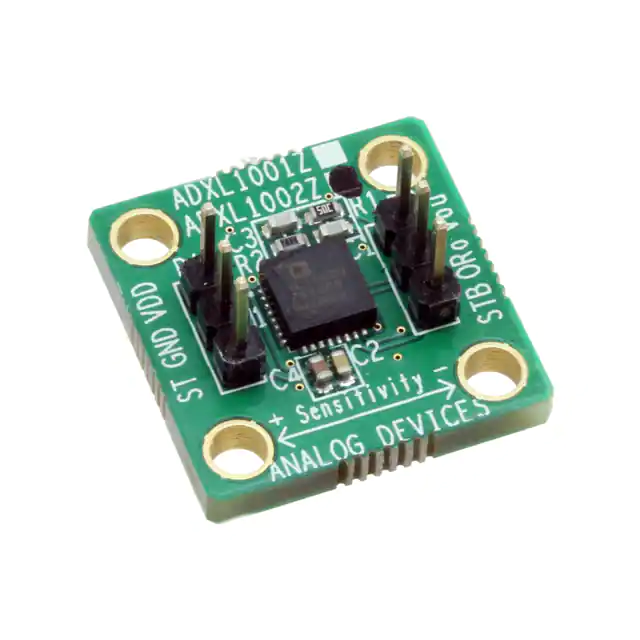


 工商网监
湘ICP备2023018690号
工商网监
湘ICP备2023018690号

