LTM8021
36VIN, 500mA
Step-Down DC/DC µModule
Features
Description
Complete Switch Mode Power Supply
Wide Input Voltage Range: 3V to 36V
500mA Output Current
0.8V to 5V Output Voltage
Fixed 1.1MHz Switching Frequency
Current Mode Control
(e4) RoHS Compliant Package with Gold
Pad Finish
n Programmable Soft-Start
n Tiny, Low Profile (11.25mm × 6.25mm × 2.82mm)
Surface Mount LGA Package
The LTM®8021 is a 36VIN 500mA, step-down DC/DC
µModule®. Included in the package are the switching
controller, power switches, inductor, and all support
components. Operating over an input voltage range of 3V
to 36V, the LTM8021 supports an output voltage range of
0.8V to 5V, set by a single resistor. Only an output and
bulk input capacitor are needed to finish the design.
n
n
n
n
n
n
n
Applications
n
n
n
n
n
The low profile package (2.82mm) enables utilization of
unused space on the bottom of PC boards for high density point of load regulation. A built-in soft-start timer is
adjustable with just a resistor and capacitor.
The LTM8021 is packaged in a thermally enhanced,
compact (11.25mm × 6.25mm) and low profile (2.82mm)
overmolded land grid array (LGA) package suitable
for automated assembly by standard surface mount
equipment. The LTM8021 is RoHS compliant.
Automotive Battery Regulation
Power for Portable Products
Distributed Supply Regulation
Industrial Supplies
Wall Transformer Regulation
L, LT, LTC, LTM, µModule, PolyPhase, Linear Technology and the Linear logo are registered
trademarks of Linear Technology Corporation. All other trademarks are the property of their
respective owners.
Typical Application
Efficiency and Power Loss
7VIN to 36VIN, 5V/500mA µModule Regulator
90
LTM8021
RUN/SS
GND
1µF
BIAS
ADJ
19.1k
2.2µF
400
80
VOUT
5V AT 500mA
OUT
70
300
250
60
200
50
POWER
LOSS
40
8021 TA01a
*RUNNING VOLTAGE RANGE. PLEASE REFER TO THE
APPLICATIONS INFORMATION SECTION FOR START-UP DETAILS.
350
EFFICIENCY
EFFICIENCY (%)
IN
30
1.00
150
POWER LOSS (mW)
VIN*
7V TO
36V
450
100
50
10.00
100.00
LOAD CURRENT (mA)
0
1000.00
8021 TA01b
8021fd
For more information www.linear.com/LTM8021
1
�LTM8021
Pin Configuration
Absolute Maximum Ratings
(Note 1)
TOP VIEW
VIN, RUN/SS Voltage..................................................40V
RUN/SS Above VIN.......................................................3V
ADJ Voltage.................................................................5V
BIAS Voltage................................................................7V
VOUT Voltage..............................................................10V
Internal Operating Temperature
Range (Note 2)........................................ –40°C to 125°C
Maximum Solder Temperature............................... 260°C
Storage Temperature Range................... –55°C to 125°C
VIN
BANK 1
5
VOUT
BANK 2
4
3
ADJ
RUN/SS
BIAS
2
GND
BANK 3
1
A
B
C
D
E
F
G
H
LGA PACKAGE
35-LEAD (11.25mm × 6.25mm × 2.82mm)
TJMAX = 125°C, θJA = 36.9°C/W, θJB = 20.9°C/W, WEIGHT = 0.49g
θJC(TOP) = 41.74°C/W, θJC(BOTTOM) = 17.8°C/W
order information
PART NUMBER
PAD OR BALL FINISH
PART MARKING*
DEVICE
FINISH CODE
PACKAGE
TYPE
MSL
RATING
TEMPERATURE RANGE
(Note 2)
LTM8021EV#PBF
Au (RoHS)
LTM8021V
e4
LGA
3
–40°C to 125°C
LTM8021IV#PBF
Au (RoHS)
LTM8021V
e4
LGA
3
–40°C to 125°C
Consult Marketing for parts specified with wider operating temperature
ranges. *Device temperature grade is indicated by a label on the shipping
container. Pad or ball finish code is per IPC/JEDEC J-STD-609.
• Recommended LGA and BGA PCB Assembly and Manufacturing
Procedures:
www.linear.com/umodule/pcbassembly
• Terminal Finish Part Marking:
www.linear.com/leadfree
• LGA and BGA Package and Tray Drawings:
www.linear.com/packaging
The
l denotes the specifications which apply over the full operating
Electrical
Characteristics
temperature range, otherwise specifications are at TA = 25°C, VIN = 10V, VRUN/SS = 10V, VBIAS = 3V, RADJ = 31.6k.
SYMBOL
PARAMETER
CONDITIONS
VIN
Input DC Voltage
VRUN/SS = 5V, RADJ = Open
VOUT
Output DC Voltage
0 < IOUT < 500mA; RADJ Open
0 < IOUT < 500mA; RADJ = 19.1k, 0.1%
RADJ(MIN)
Minimum Allowable RADJ
Note 3
ILK
Leakage from IN to OUT
RUN/SS = VBIAS = 0V, RADJ Open
MIN
TYP
3
MAX
36
0.8
5
UNITS
V
V
V
18
kW
2.7
0
6
µA
500
mA
1
2.5
µA
mA
IOUT
Continuous Output DC Current
5V ≤ VIN ≤ 36V, VBIAS = VOUT
IQ(VIN)
Quiescent Current into VIN
RUN/SS = 0.2V, VBIAS , RADJ Open
Not Switching
0.1
1.5
IQ(BIAS)
Quiescent Current into BIAS
Not Switching
0.15
µA
∆VOUT/VOUT
Line Regulation
5V ≤ VIN ≤ 36V, IOUT = 500mA
RADJ = Open
0.5
%
∆VOUT/VOUT
Load Regulation
VIN = 24V, 0 ≤ IOUT ≤ 500mA, VBIAS = VOUT
0.35
%
8021fd
2
For more information www.linear.com/LTM8021
�LTM8021
Electrical
Characteristics
The
l denotes the specifications which apply over the full operating
temperature range, otherwise specifications are at TA = 25°C, VIN = 10V, VRUN/SS = 10V, VBIAS = 3V, RADJ = 31.6k.
SYMBOL
PARAMETER
CONDITIONS
VOUT(DC)
DC Output Voltage
VIN = 24V, 0 ≤ IOUT ≤ 500mA
RADJ = 31.6k, 0.1%
MIN
TYP
MAX
UNITS
VOUT(AC_RMS)
Output Voltage Ripple (RMS)
VIN = 24V, IOUT = 250mA
COUT = 2.2µF, VBIAS = VOUT
fSW
Switching Frequency
IOUT = 500mA
IOSC
Short-Circuit Output Current
VIN = 36V, VBIAS = VOUT = 0V
900
mA
IISC
Short-Circuit Input Current
VIN = 36V, VBIAS = VOUT = 0V
25
mA
ADJ
Voltage at ADJ Pin
RADJ Open
VBIAS(MIN)
Minimum BIAS Voltage for Proper
Operation
IADJ
3.3
V
1
0.9
1.3
MHz
0.80
0.83
V
IOUT = 500mA
2.2
3
V
Current Out of ADJ Pin
VOUT = 5V, VADJ = 0V, RUN/SS = 0V
50
µA
IRUN/SS
RUN/SS Pin Current
VRUN/SS = 2.5V, RADJ Open
23
µA
VIH(RUN/SS)
RUN/SS Input High Voltage
RADJ Open, IOUT = 500mA
VIL(RUN/SS)
RUN/SS Input Low Voltage
RADJ Open, IOUT = 500mA
RFB
Internal Feedback Resistor
RUN/SS = VBIAS = VADJ = 0V
Note 1: Stresses beyond those listed under Absolute Maximum Ratings
may cause permanent damage to the device. Exposure to any Absolute
Maximum Rating condition for extended periods may affect device
reliability and lifetime.
Note 2: The LTM8021E is guaranteed to meet performance specifications
from 0°C to 125°C internal. Specifications over the full –40°C to 125°C
internal operating temperature range are assured by design,
l
0.79
1.1
mV
1.6
V
0.5
100
V
kW
characterization and correlation with statistical process controls. The
LTM8021I is guaranteed to meet specifications over the full –40°C to
125°C internal operating temperature range. Note that the maximum
internal temperature is determined by specific operating conditions in
conjunction with board layout, the rated package thermal resistance and
other environmental factors.
Note 3: Guaranteed by design.
8021fd
For more information www.linear.com/LTM8021
3
�LTM8021
Typical Performance Characteristics
VOUT = 1.8V
80
VIN = 5V
75
VIN = 12V
70
VIN = 24V
65
VIN = 36V
60
55
Efficiency vs Load Current
90
VIN = 5V
VIN = 12V
75
VIN = 24V
VIN = 36V
50
0
VIN = 36V
75
70
60
VOUT = 0.8V
0
VIN = 5V
3
2
VIN = 12V
100
0
300
400
200
LOAD CURRENT (mA)
500
BIAS CURRENT (mA)
BIAS CURRENT (mA)
VIN = 12V
VIN = 24V
VIN = 24V
100
0
300
400
200
LOAD CURRENT (mA)
500
600
8021 G06
VIN = 5V
7
6
5
VIN = 12V
4
3
VIN = 24V
2
1
1
0
0
100
0
600
8
5
0
VIN = 12V
VOUT = 3.3V
9
6
2
3
IBIAS vs Load Current
10
VIN = 5V
3
4
8021 G05
VOUT = 2.5V
4
VIN = 5V
5
1
VIN = 24V
IBIAS vs Load Current
7
6
2
8021 G04
8
VIN = 3.4V
7
4
0
50 100 150 200 250 300 350 400 450 500
LOAD CURRENT (mA)
VOUT = 1.8V
8
VIN = 3.4V
1
65
IBIAS vs Load Current
9
BIAS CURRENT (mA)
VIN = 24V
80
50 100 150 200 250 300 350 400 450 500
LOAD CURRENT (mA)
8021 G03
IBIAS vs Load Current
5
BIAS CURRENT (mA)
EFFICIENCY (%)
6
VIN = 12V
85
0
8021 G02
Efficiency vs Load Current
VOUT = 5V
VIN = 36V
70
55
50 100 150 200 250 300 350 400 450 500
LOAD CURRENT (mA)
8021 G01
90
75
60
55
50 100 150 200 250 300 350 400 450 500
LOAD CURRENT (mA)
VIN = 24V
65
60
0
VIN = 5V
VIN = 12V
80
65
45
VOUT = 3.3V
85
80
70
50
40
VOUT = 2.5V
85
EFFICIENCY (%)
85
EFFICIENCY (%)
Efficiency vs Load Current
90
EFFICIENCY (%)
Efficiency vs Load Current
90
TA = 25°C, unless otherwise noted
300
400
200
LOAD CURRENT (mA)
500
600
0
100
8021 G07
300
400
200
LOAD CURRENT (mA)
500
600
8021 G08
8021fd
4
For more information www.linear.com/LTM8021
�LTM8021
Typical Performance Characteristics
Input Current vs Output Current
VIN = 5V
INPUT CURRENT (mA)
VOUT = 2.5V
200
150
VOUT = 1.8V
100
VOUT = 5V
200
VOUT = 3.3V
150
VOUT = 2.5V
100
50
0
50 100 150 200 250 300 350 400 450 500
OUTPUT CURRENT (mA)
40
VOUT = 1.8V
20
0
0
50 100 150 200 250 300 350 400 450 500
OUTPUT CURRENT (mA)
8021 G11
Minimum Input Running Voltage
vs Output Voltage
7
VO = 3.3V
IOUT = 500mA
6
INPUT VOLTAGE (V)
2500
2000
1500
1000
500
0
VOUT = 2.5V
60
8021 G10
Input Quiescent Current
vs Input Voltage
3000
VOUT = 3.3V
80
50 100 150 200 250 300 350 400 450 500
OUTPUT CURRENT (mA)
0
8021 G09
INPUT QUIESCENT CURRENT (µA)
5
4
3
2
1
0
5
10
15 20 25 30
INPUT VOLTAGE (V)
35
0
40
1
0
3
4
2
OUTPUT VOLTAGE (V)
8021 G13
Output Short-Circuit Current
vs Input Voltage
900
Radiated Emissions
90
VOUT = 3.3V
880
36VIN
5VOUT
FULL LOAD
80
860
840
820
800
780
760
740
720
6
5
8021 G12
EMISSIONS LEVEL (dBµV/m)
0
VOUT = 5V
100
VOUT = 1.8V
50
OUTPUT CURRENT (mA)
INPUT CURRENT (mA)
250
VIN = 24V
120
250
300
0
140
VIN = 12V
VOUT = 3.3V
350
Input Current vs Output Current
Input Current vs Output Current
300
INPUT CURRENT (mA)
400
TA = 25°C, unless otherwise noted
70
60
50
CISPR22
CLASS B LIMIT
40
30
20
10
0
4
8
12
16
20
24
28
32
36
–10
0
INPUT VOLTAGE (V)
8021 G14
200
600
800
400
FREQUENCY (MHz)
1000
8021 G15
8021fd
For more information www.linear.com/LTM8021
5
�LTM8021
Pin Functions
VIN (Bank 1): The VIN pin supplies current to the LTM8021’s
internal regulator and to the internal power switch. This
pin must be locally bypassed with an external, low ESR
capacitor of at least 1µF.
VOUT (Bank 2): Power Output Pins. An external capacitor is
connected from VOUT to GND in most applications. Apply
output load between these pins and GND pins.
BIAS (Pin H3): The BIAS pin connects to the internal
boost Schottky diode and to the internal regulator. Tie to
VOUT when VOUT > 3V or to another DC voltage greater
than 3V otherwise. When BIAS > 3V the internal circuitry
will be powered from this pin to improve efficiency. Main
regulator power will still come from VIN.
RUN/SS (Pin A1): Tie RUN/SS pin to ground to shut down
the LTM8021. Tie to 1.6V or more for normal operation.
If the shutdown feature is not used, tie this pin to the VIN
pin. The RUN/SS also provides soft-start and frequency
foldback. To use the soft-start function, connect a resistor
and capacitor to this pin. Do not allow the RUN/SS pin to
rise above VIN. See the Applications Information section.
GND (Bank 3): The GND connections serve as the main
signal return and the primary heat sink for the LTM8021. Tie
the GND pins to a local ground plane below the LTM8021
and the circuit components. Return the feedback divider
to this signal.
ADJ (Pin A2): The LTM8021 regulates its ADJ pin to
0.8V. Connect the adjust resistor from this pin to ground.
The value of RADJ is given by the equation, RADJ = 80/
(VOUT – 0.8), where RADJ is in k.
Block Diagram
VIN
VOUT
10µH
0.1µF
15pF
100k
1%
10µF
BIAS
RUN/SS
CURRENT MODE
CONTROLLER
GND
ADJ
8021 BD
8021fd
6
For more information www.linear.com/LTM8021
�LTM8021
Operation
The LTM8021 is a standalone nonisolated step-down
switching DC/DC power supply. It can deliver up to
500mA of DC output current with only bulk external input
and output capacitors. This module provides a precisely
regulated output voltage programmable via one external
resistor from 0.8VDC to 5VDC . The input voltage range is 3V
to 36V. Given that the LTM8021 is a step-down converter,
make sure that the input voltage is high enough to support
the desired output voltage and load current. Please refer
to the simplified Block Diagram.
The LTM8021 contains a current mode controller, power
switching element, power inductor, power Schottky diode
and a modest amount of input and output capacitance.
With its high performance current mode controller and
internal feedback loop compensation, the LTM8021 module
has sufficient stability margin and good transient performance under a wide range of operating conditions with a
wide range of output capacitors, even all ceramic ones (X5R
or X7R). Current mode control provides cycle-by-cycle
fast current limit, and automatic current limiting protects
the module in the event of a short circuit or overload fault.
The LTM8021 is based upon a 1.1MHz fixed frequency
PWM current mode controller, equipped with cycle skip
capability for low voltage outputs or light loads. A frequency
foldback scheme helps to protect internal components from
overstress under heavy and short-circuit output loads.
The drive circuit for the internal power switching element
is powered through the BIAS pin. Power this pin with at
least 3V.
APPLICATIONS INFORMATION
For most applications, the design process is straight
forward, summarized as follows:
1. Refer to Table 1 for the row that has the desired input
range and output voltage.
2. Apply the recommended CIN, COUT and RADJ values.
3. Connect BIAS as indicated.
While these component combinations have been tested for
proper operation, it is incumbent upon the user to verify
proper operation over the intended system’s line, load and
environmental conditions.
If the desired output voltage is not listed in Table 1, set the
output by applying an RADJ resistor whose value is given
by the equation, RADJ = 80/(VOUT – 0.80), where RADJ is
in k and VOUT is in volts. Verify the LTM8021’s operation
over the system’s intended line, load and environmental
conditions.
Minimum Duty Cycle
The LTM8021 has a fixed 1.1MHz switching frequency. For
any given output voltage, the duty cycle falls as the input
voltage rises. At very large VIN to VOUT ratios, the duty
cycle can be very small. Because the LTM8021’s internal
controller IC has a minimum on-time, the regulator will
skip cycles in order to maintain output voltage regulation.
This will result in a larger output voltage ripple and possible
disturbances during recovery from a transient load step.
The component values provided in Table 1 allow for skip
cycle operation, but hold the resultant output ripple to
around 50mV, or less. If even less ripple is desired, then
more output capacitance may be necessary. Adding a feedforward capacitor has been empirically shown to modestly
extend the input voltage range to where the LTM8021 does
not skip cycles. Apply the feedforward capacitor between
the VOUT pins and ADJ. This injects perturbations into the
control loop, therefore, values larger than 50pF are not
recommended. A good value to start with is 12pF.
8021fd
For more information www.linear.com/LTM8021
7
�LTM8021
Applications Information
Table 1. Recommended Component Values and Configuration
VIN RANGE
VOUT
CIN
COUT
RADJ
BIAS
3.4V to 36V
0.8V
4.7µF
100µF 1210
8.2M
3V to 7V
3.4V to 36V
1.2V
4.7µF
100µF 1210
200k
3V to 7V
3.4V to 36V
1.5V
4.7µF
100µF 1210
115k
3V to 7V
3.4V to 36V
1.8V
2.2µF
100µF 1210
78.7k
3V to 7V
3.5V to 36V
2V
2.2µF
100µF 1210
66.5k
3V to 7V
4V to 36V
2.2V
1µF
22µF 1206
57.6k
3V to 7V
4V to 36V
2.5V
1µF
10µF 0805
47.5k
3V to 7V
5V to 36V
3.3V
1µF
4.7µF 0805
32.4k
VOUT
7V to 36V
5V
1µF
2.2µF 0805
19.1k
VOUT
3.5V to 32V
–3.3V
1µF
4.7µF 0805
32.4k
GND
3.75V to 31V
–5V
1µF
4.7µF 0805
19.1k
GND
3.4V to 15V
0.8V
4.7µF
100µF 1210
8.2M
3V to 7V
3.4V to 15V
1.2V
4.7µF
100µF 1210
200k
3V to 7V
3.4V to 15V
1.5V
4.7µF
47µF 1206
115k
3V to 7V
3.4V to 15V
1.8V
2.2µF
47µF 1206
78.7k
3V to 7V
3.5V to 15V
2V
2.2µF
22µF 1206
66.5k
3V to 7V
4V to 15V
2.2V
1µF
22µF 1206
57.6k
3V to 7V
4V to 15V
2.5V
1µF
10µF 0805
47.5k
3V to 7V
5V to 15V
3.3V
1µF
2.2µF 0805
32.4k
VOUT
7V to 15V
5V
1µF
1µF 0805
19.1k
VOUT
9V to 24V
0.8V
1µF
100µF 1210
Open
3V to 7V
9V to 24V
1.2V
1µF
100µF 1210
200k
3V to 7V
9V to 24V
1.5V
1µF
47µF 1206
115k
3V to 7V
9V to 24V
1.8V
1µF
47µF 1206
78.7k
3V to 7V
9V to 24V
2V
1µF
22µF 1206
66.5k
3V to 7V
9V to 24V
2.2V
1µF
22µF 1206
57.6k
3V to 7V
9V to 24V
2.5V
1µF
10µF 0805
47.5k
3V to 7V
9V to 24V
3.3V
1µF
2.2µF 0805
32.4k
VOUT
9V to 24V
5V
1µF
1µF 0805
19.1k
VOUT
18V to 36V
0.8V
1uF
100µF 1210
Open
3V to 7V
18V to 36V
1.2V
1uF
100µF 1210
200k
3V to 7V
18V to 36V
1.5V
1uF
100µF 1210
115k
3V to 7V
18V to 36V
1.8V
1uF
100µF 1210
78.7k
3V to 7V
18V to 36V
2V
1uF
100µF 1210
66.5k
3V to 7V
18V to 36V
2.2V
1uF
22µF 1206
57.6k
3V to 7V
18V to 36V
2.5V
1uF
10µF 0805
47.5k
3V to 7V
18V to 36V
3.3V
1uF
4.7µF 0805
32.4k
VOUT
18V to 36V
5V
1uF
2.2µF 0805
19.1k
VOUT
8021fd
8
For more information www.linear.com/LTM8021
�LTM8021
Applications Information
If this audible noise is unacceptable, use a high performance
electrolytic capacitor at the output. This output capacitor
can be a parallel combination of a 1µF ceramic capacitor
and a low cost electrolytic capacitor.
Capacitor Selection Considerations
The CIN and COUT capacitor values in Table 1 are the
minimum recommended values for the associated operating conditions. Applying capacitor values below those
indicated in Table 1 is not recommended, and may result
in undesirable operation. Using larger values is generally
acceptable, and can yield improved dynamic response or
fault recovery, if it is necessary. Again, it is incumbent
upon the user to verify proper operation over the intended
system’s line, load and environmental conditions.
A final precaution regarding ceramic capacitors concerns the maximum input voltage rating of the LTM8021.
A ceramic input capacitor combined with trace or cable
inductance forms a high Q (under damped) tank circuit.
If the LTM8021 circuit is plugged into a live supply, the
input voltage can ring to twice its nominal value, possibly exceeding the device’s rating. This situation is easily
avoided; see the Hot-Plugging Safely section.
Ceramic capacitors are small, robust and have very low
ESR. However, not all ceramic capacitors are suitable.
X5R and X7R types are stable over temperature and applied voltage and give dependable service. Other types,
including Y5V and Z5U have very large temperature and
voltage coefficients of capacitance. In an application circuit they may have only a small fraction of their nominal
capacitance resulting in much higher output voltage ripple
than expected.
Minimum Input Voltage
The LTM8021 is a step-down converter, so a minimum
amount of headroom is required to keep the output in
regulation. For most applications at full load, the input
must be about 1.5V above the desired output. In addition,
it takes more input voltage to turn on than is required for
continuous operation. This is shown in Figure 1.
Ceramic capacitors are also piezoelectric. At light loads,
the LTM8021 skips switching cycles in order to maintain
regulation. The resulting bursts of current can excite
a ceramic capacitor at audio frequencies, generating
audible noise.
6.0
VOUT = 5V
INPUT VOLTAGE (V)
7
6
VOUT = 3.3V
5.5
TO START
RUN/SS
ENABLED
5
TO RUN
4
3
2
0.001
TO START
5.0
INPUT VOLTAGE (V)
8
4.5
4.0
RUN/SS
ENABLED
3.5
TO RUN
3.0
2.5
0.01
0.1
LOAD CURRENT (A)
1
2.0
0.001
0.01
0.1
LOAD CURRENT (A)
1
8021 F01
Figure 1. The LTM8021 Requires More Voltage to Start Than to Run
8021fd
For more information www.linear.com/LTM8021
9
�LTM8021
Applications Information
Soft-Start
The RUN/SS pin can be used to soft-start the LTM8021,
reducing the maximum input current during start-up.
The RUN/SS pin is driven through an external RC filter
to create a voltage ramp at this pin. Figure 2 shows the
soft-start circuit. By choosing a large RC time constant,
the peak start-up current can be reduced to the current
that is required to regulate the output, with no overshoot.
Choose the value of the resistor so that it can supply 80µA
when the RUN/SS pin reaches 2V.
PCB Layout
Most of the problems associated with the PCB layout
have been alleviated or eliminated by the high level of
integration of the LTM8021. The LTM8021 is nevertheless
a switching power supply, and care must be taken to
minimize EMI and ensure proper operation. Even with the
high level of integration, one may fail to achieve a specified
operation with a haphazard or poor layout. See Figure 4
for a suggested layout.
RUN
15k
RUN/SS
0.22µF
your system can tolerate a few milliamps in this state. If
the RUN/SS pin is grounded, the internal power switch
current will drop to essentially zero. However, if the VIN pin
is grounded while the output is held high, then parasitic
diodes inside the LTM8021 can pull large currents from
the output through the internal power switch and the VIN
pin. Figure 3 shows a circuit that will run only when the
input voltage is present and that protects against a shorted
or reversed input.
GND
8021 F02
Figure 2. To Soft-Start the LTM8021, Add a
Resistor and Capacitor to the RUN/SS Pin
Shorted Input Protection
Care needs to be taken in systems where the output will
be held high when the input to the LTM8021 is absent.
This may occur in battery charging applications or in
battery backup systems where a battery or some other
supply is diode ORed with the LTM8021’s output. If the
VIN pin is allowed to float and the RUN/SS pin is held high
(either by a logic signal or because it is tied to VIN), then
the LTM8021’s internal circuitry will pull its quiescent
current through its internal power switch. This is fine if
Ensure that the grounding and heatsinking are acceptable.
A few rules to keep in mind are:
1. Place the CIN capacitor as close as possible to the VIN
and GND connection of the LTM8021.
2. Place the COUT capacitor as close as possible to the
VOUT and GND connection of the LTM8021.
3. Place the CIN and COUT capacitors such that their ground
currents flow directly adjacent to, or underneath the
LTM8021.
VIN
GND
PLANE VOUT
LTM8021
VIN
VOUT
RUN/SS
BIAS
GND
CIN
CIN
VOUT
RT
COUT
RADJ
RADJ
8021 F03
Figure 3. The Input Diode Prevents a Shorted Input from
Discharging a Backup Battery Tied to the Output. It Also Protects
the Circuit from a Reversed Input. The LTM8021 Runs Only When
the Input is Present
10
COUT
BIAS
VIN
4V TO 36V
FB
RUN/SS
8021 F04
Figure 4. Layout Showing Suggested External Components,
GND Plane and Thermal Vias
For more information www.linear.com/LTM8021
8021fd
�LTM8021
Applications Information
CLOSING SWITCH
SIMULATES HOT PLUG
IIN
VIN
+
LOW
IMPEDANCE
ENERGIZED
24V SUPPLY
+
VIN
20V/DIV
DANGER
RINGING VIN MAY EXCEED
ABSOLUTE MAXIMUM RATING
LTM8021
4.7µF
IIN
10A/DIV
STRAY
INDUCTANCE
DUE TO 6 FEET
(2 METERS) OF
TWISTED PAIR
+
20µs/DIV
(5a)
LTM8021
22µF
AI.EI.
VIN
20V/DIV
4.7µF
IIN
10A/DIV
(5b)
0.7Ω
+
0.1µF
LTM8021
20µs/DIV
VIN
20V/DIV
4.7µF
IIN
10A/DIV
(5c)
20µs/DIV
8021 F05
Figure 5. Ensures Reliable Operation When the LTM8021 is Connected to a Live Supply
4. Connect all of the GND connections to as large a
copper pour or plane area as possible on the top layer.
Avoid breaking the ground connection between the
external components and the LTM8021.
Hot-Plugging Safely
The small size, robustness and low impedance of ceramic
capacitors make them an attractive option for the input
bypass capacitor of LTM8021. However, these capacitors
can cause problems if the LTM8021 is plugged into a live
supply (see the Linear Technology Application Note 88 for
a complete discussion). The low loss ceramic capacitor
combined with stray inductance in series with the power
source forms an under damped tank circuit, and the voltage at the VIN pin of the LTM8021 can ring to twice the
nominal input voltage, possibly exceeding the LTM8021’s
rating and damaging the part. If the input supply is poorly
controlled or the user will be plugging the LTM8021 into
an energized supply, the input network should be designed
to prevent this overshoot. Figure 5 shows the waveforms
that result when an LTM8021 circuit is connected to a 24V
supply through six feet of 24-gauge twisted pair. The first
plot is the response with a 2.2µF ceramic capacitor at the
input. The input voltage rings as high as 35V and the input
current peaks at 20A. One method of damping the tank
circuit is to add another capacitor with a series resistor to
8021fd
For more information www.linear.com/LTM8021
11
�LTM8021
Applications Information
the circuit. In Figure 5b an aluminum electrolytic capacitor
has been added. This capacitor’s high equivalent series
resistance damps the circuit and eliminates the voltage
overshoot. The extra capacitor improves low frequency
ripple filtering and can slightly improve the efficiency of the
circuit, though it is likely to be the largest component in the
circuit. An alternative solution is shown in Figure 5c. A 0.7W
resistor is added in series with the input to eliminate the
voltage overshoot (it also reduces the peak input current).
A 0.1µF capacitor improves high frequency filtering. This
solution is smaller and less expensive than the electrolytic
capacitor. For high input voltages its impact on efficiency
is minor, reducing efficiency less than one-half percent for
a 5V output at full load operating from 24V.
Thermal Considerations
The LTM8021 output current may need to be derated if it
is required to operate in a high ambient temperature or
deliver a large amount of continuous power. The amount
of current derating is dependent upon the input voltage,
output power and ambient temperature. The temperature
rise curves given in the Typical Performance Characteristics section can be used as a guide. These curves
were generated by a LTM8021 mounted to a 40.3cm2
4-layer FR4 printed circuit board. Boards of other sizes
and layer count can exhibit different thermal behavior, so
it is incumbent upon the user to verify proper operation
over the intended system’s line, load and environmental
operating conditions.
The thermal resistance numbers listed in Page 2 of the
data sheet are based on modeling the µModule package
mounted on a test board specified per JESD51-9 (Test
Boards for Area Array Surface Mount Package Thermal
Measurements). The thermal coefficients provided in this
page are based on JESD 51-12 (Guidelines for Reporting
and Using Electronic Package Thermal Information).
For increased accuracy and fidelity to the actual application,
many designers use FEA to predict thermal performance.
To that end, Page 2 of the data sheet typically gives four
thermal coefficients:
θJA – Thermal resistance from junction to ambient.
θJCbottom – Thermal resistance from junction to the bottom
of the product case.
θJCtop – Thermal resistance from junction to top of the
product case.
θJB – Thermal resistance from junction to the printed
circuit board.
While the meaning of each of these coefficients may seem
to be intuitive, JEDEC has defined each to avoid confusion
and inconsistency. These definitions are given in JESD
51-12, and are quoted or paraphrased below:
θJA is the natural convection junction-to-ambient air
thermal resistance measured in a one cubic foot sealed
enclosure. This environment is sometimes referred to as
still air although natural convection causes the air to move.
This value is determined with the part mounted to a JESD
51-9 defined test board, which does not reflect an actual
application or viable operating condition.
θJCbottom is the thermal resistance between the junction
and bottom of the package with all of the component power
dissipation flowing through the bottom of the package. In
the typical µModule converter, the bulk of the heat flows
out the bottom of the package, but there is always heat
flow out into the ambient environment. As a result, this
thermal resistance value may be useful for comparing
packages but the test conditions don’t generally match
the user’s application.
θJCtop is determined with nearly all of the component power
dissipation flowing through the top of the package. As the
electrical connections of the typical µModule converter are
on the bottom of the package, it is rare for an application
to operate such that most of the heat flows from the junction to the top of the part. As in the case of θJCbottom, this
value may be useful for comparing packages but the test
conditions don’t generally match the user’s application.
8021fd
12
For more information www.linear.com/LTM8021
�LTM8021
Applications Information
θJB is the junction-to-board thermal resistance where
almost all of the heat flows through the bottom of the
µModule converter and into the board, and is really the
sum of the θJCbottom and the thermal resistance of the
bottom of the part through the solder joints and through a
portion of the board. The board temperature is measured
a specified distance from the package, using a two sided,
two layer board. This board is described in JESD 51-9.
Given these definitions, it should now be apparent that none
of these thermal coefficients reflects an actual physical
operating condition of a µModule converter. Thus, none
of them can be individually used to accurately predict the
thermal performance of the product. Likewise, it would
be inappropriate to attempt to use any one coefficient to
correlate to the junction temperature vs load graphs given
in the product’s data sheet. The only appropriate way to
use the coefficients is when running a detailed thermal
analysis, such as FEA, which considers all of the thermal
resistances simultaneously.
A graphical representation of these thermal resistances
is given in Figure 6.
The blue resistances are contained within the µModule
converter, and the green are outside.
The die temperature of the LTM8021 must be lower than
the maximum rating of 125°C, so care should be taken in
the layout of the circuit to ensure good heat sinking of the
LTM8021. The bulk of the heat flow out of the LTM8021
is through the bottom of the μModule converter and the
LGA pads into the printed circuit board. Consequently a
poor printed circuit board design can cause excessive
heating, resulting in impaired performance or reliability.
Please refer to the PCB Layout section for printed circuit
board design suggestions.
JUNCTION-TO-AMBIENT RESISTANCE (JESD 51-9 DEFINED BOARD)
JUNCTION-TO-CASE (TOP)
RESISTANCE
JUNCTION
CASE (TOP)-TO-AMBIENT
RESISTANCE
JUNCTION-TO-BOARD RESISTANCE
JUNCTION-TO-CASE
CASE (BOTTOM)-TO-BOARD
(BOTTOM) RESISTANCE
RESISTANCE
AMBIENT
BOARD-TO-AMBIENT
RESISTANCE
8021 F06
µMODULE DEVICE
Figure 6. Thermal Model of µModule Regulator
8021fd
For more information www.linear.com/LTM8021
13
�LTM8021
typical Applications
1.8V Step-Down Converter
0.8V Step-Down Converter
VIN*
3.4V TO 36V
LTM8021
VIN
5V
5V
GND
LTM8021
VIN
BIAS
RUN/SS
1µF
VIN*
3.4V TO 36V
VOUT
0.8V AT 500mA
VOUT
VOUT
1.8V AT 500mA
VOUT
BIAS
RUN/SS
100µF
GND
ADJ
100µF
ADJ
1µF
78.7k
8021 TA02
8021 TA03
*RUNNING VOLTAGE RANGE. PLEASE REFER TO THE
APPLICATIONS INFORMATION SECTION FOR START-UP DETAILS.
*RUNNING VOLTAGE RANGE. PLEASE REFER TO THE
APPLICATIONS INFORMATION SECTION FOR START-UP DETAILS.
5V Step-Down Converter
VIN*
7V TO 36V
VIN
LTM8021
RUN/SS
GND
1µF
VOUT
5V AT 500mA
VOUT
BIAS
ADJ
2.2µF
19.1k
8021 TA04
*RUNNING VOLTAGE RANGE. PLEASE REFER TO THE
APPLICATIONS INFORMATION SECTION FOR START-UP DETAILS.
–5V Positive-to-Negative Converter
Load Current vs Input Voltage
600
VIN
LTM8021
RUN/SS
500
VOUT
400
BIAS
4.7µF
GND
1µF
ADJ
OPTIONAL
SCHOTTKY
CLAMP
19.1k
–5V
8021 TA05
*RUNNING VOLTAGE RANGE. PLEASE REFER TO THE
APPLICATIONS INFORMATION SECTION FOR START-UP DETAILS.
ILOAD (mA)
VIN*
3.75V TO 31V
300
200
100
0
0
5
10
15
20
25
VIN (V)
8021 TA05b
8021fd
14
For more information www.linear.com/LTM8021
�LTM8021
Package Description
Please refer to http://www.linear.com/designtools/packaging/ for the most recent package drawings.
LGA Package
35-Lead (11.25mm × 6.25mm × 2.82mm)
(Reference LTC DWG # 05-08-1805 Rev B)
11.250
BSC
aaa Z
2.72 – 2.92
X
Y
MOLD
CAP
6.250
BSC
SUBSTRATE
0.27 – 0.37
PAD 1
CORNER
Z
bbb Z
2.40 – 2.60
DETAIL A
aaa Z
PACKAGE TOP VIEW
4
4.445
3.175
1.905
0.635
0.0000
0.635
1.905
3.175
4.445
DETAIL A
PACKAGE SIDE VIEW
8.890
BSC
0.605 – 0.665
PADS
SEE NOTES
SEE NOTES
7
3
5
2.540
1.270
4
0.605 – 0.665
5.080
BSC
0.0000
0.9525
1.270
1.5875
3
2
1.270
BSC
2.540
1
0.9525
0.635
0.3175
H
G
F
E
D
C
B
A
PAD 1
C (0.30)
PACKAGE BOTTOM VIEW
SUGGESTED PCB LAYOUT
TOP VIEW
NOTES:
1. DIMENSIONING AND TOLERANCING PER ASME Y14.5M-1994
2. ALL DIMENSIONS ARE IN MILLIMETERS
3
LAND DESIGNATION PER JESD MO-222, SPP-010 AND SPP-020
4
DETAILS OF PAD #1 IDENTIFIER ARE OPTIONAL,
BUT MUST BE LOCATED WITHIN THE ZONE INDICATED.
THE PAD #1 IDENTIFIER MAY BE EITHER A MOLD OR A
MARKED FEATURE
5. PRIMARY DATUM -Z- IS SEATING PLANE
6. THE TOTAL NUMBER OF PADS: 35
7
!
PACKAGE ROW AND COLUMN LABELING MAY VARY
AMONG µModule PRODUCTS. REVIEW EACH PACKAGE
LAYOUT CAREFULLY
SYMBOL TOLERANCE
aaa
0.15
bbb
0.10
LTMXXXXXX
µModule
COMPONENT
PIN “A1”
TRAY PIN 1
BEVEL
PACKAGE IN TRAY LOADING ORIENTATION
LGA 35 0113 REV B
8021fd
For more information www.linear.com/LTM8021
15
�LTM8021
Package Description
LTM8021 Pinout (Sorted by Pin Number)
PIN
SIGNAL DESCRIPTION
A1
RUN/SS
A2
ADJ
A4
VIN
A5
VIN
B1
GND
B2
GND
B4
VIN
B5
VIN
C1
GND
C2
GND
D1
GND
D2
GND
D3
GND
D4
GND
D5
GND
E1
GND
E2
GND
E3
GND
E4
GND
E5
GND
F1
GND
F2
GND
F3
VOUT
F4
VOUT
F5
VOUT
G1
GND
G2
GND
G3
VOUT
G4
VOUT
G5
VOUT
H1
GND
H2
GND
H3
BIAS
H4
VOUT
H5
VOUT
8021fd
16
For more information www.linear.com/LTM8021
�LTM8021
Revision History
(Revision history begins at Rev D)
REV
DATE
DESCRIPTION
D
3/14
Updated thermal resistance values
PAGE NUMBER
Updated Order Information table
Updated Thermal Considerations section
2
2
12, 13
8021fd
Information furnished by Linear Technology Corporation is believed to be accurate and reliable.
However, no responsibility is assumed for its use. Linear Technology Corporation makes no representation
Forofmore
information
www.linear.com/LTM8021
that the interconnection
its circuits
as described
herein will not infringe on existing patent rights.
17
�LTM8021
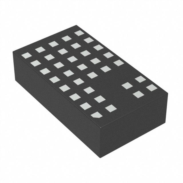
Package Photo
typical Application
3.3V Step-Down Converter
VIN*
5.5V TO 36V
LTM8021
VIN
RUN/SS
GND
1µF
VOUT
VOUT
3.3V AT 500mA
BIAS
ADJ
32.4k
4.7µF
8021 TA06
*RUNNING VOLTAGE RANGE. PLEASE REFER TO THE
APPLICATIONS INFORMATION SECTION FOR START-UP DETAILS.
Related Parts
PART NUMBER
DESCRIPTION
COMMENTS
LTM4600
10A DC/DC µModule
Basic 10A DC/DC µModule, 15mm × 15mm × 2.8mm LGA
LTM4600HVMPV
Military Plastic 10A DC/DC µModule
–55°C to 125°C Operation, 15mm × 15mm × 2.8mm LGA
LTM4601/
LTM4601A
12A DC/DC µModule with PLL, Output Tracking/Margining
and Remote Sensing
Synchronizable, PolyPhase® Operation, LTM4601-1 Version Has No
Remote Sensing
LTM4602
6A DC/DC µModule
Pin-Compatible with the LTM4600
LTM4603
6A DC/DC µModule with PLL and Output Tracking/
Margining and Remote Sensing
Synchronizable, PolyPhase Operation, LTM4603-1 Version Has No
Remote Sensing, Pin-Compatible with the LTM4601
LTM4604
4A Low VIN DC/DC µModule
2.375V ≤ VIN ≤ 5V, 0.8V ≤ VOUT ≤ 5V, 9mm × 15mm × 2.3mm LGA
LTM4605
5A to 12A Buck-Boost µModule
High Efficiency, Adjustable Frequency, 4.5V ≤ VIN ≤ 20V, 0.8V ≤ VOUT ≤
16V, 15mm × 15mm × 2.8mm
LTM4607
5A to 12A Buck-Boost µModule
High Efficiency, Adjustable Frequency, 4.5V ≤ VIN ≤ 36V, 0.8V ≤ VOUT ≤
25V, 15mm × 15mm × 2.8mm
LTM4608
8A Low VIN DC/DC µModule
2.375V ≤ VIN ≤ 5V, 0.8V ≤ VOUT ≤ 5V, 9mm × 15mm × 2.8mm LGA
LTM8020
36V, 200mA DC/DC µModule
4V ≤ VIN ≤ 36V, 1.25V ≤ VOUT ≤ 5V, 6.25mm × 6.25mm × 2.3mm LGA
LTM8022
1A, 36V DC/DC µModule
Adjustable Frequency, 0.8V ≤ VOUT ≤ 5V, 11.25mm × 9mm × 2.82mm,
Pin-Compatible to the LTM8023
LTM8023
2A, 36V DC/DC µModule
Adjustable Frequency, 0.8V ≤ VOUT ≤ 5V, 11.25mm × 9mm × 2.82mm,
Pin-Compatible to the LTM8022
8021fd
18 Linear Technology Corporation
1630 McCarthy Blvd., Milpitas, CA 95035-7417
For more information www.linear.com/LTM8021
(408) 432-1900 ● FAX: (408) 434-0507
●
www.linear.com/LTM8021
LT 0314 REV D • PRINTED IN USA
LINEAR TECHNOLOGY CORPORATION 2008
�


 工商网监
湘ICP备2023018690号
工商网监
湘ICP备2023018690号
