AMT49400
Integrated Sensorless FOC BLDC Driver
FEATURES AND BENEFITS
DESCRIPTION
•
•
•
•
The AMT49400 is an advanced 3-phase, sensorless, brushless
DC (BLDC) motor driver with integrated power MOSFETs.
•
•
•
•
•
•
•
•
Coding-free sensorless field-oriented control (FOC)
Standby mode current less than 10 µA
Quiet and quick startup
Only two external components for minimal application
circuit
PWM speed input, FG speed output
Lock detection
Soft-on soft-off (SOSO)
Optional closed-loop speed control
Configurable current limit
Windmill and reverse windmill operation
Lock detection
Short-circuit protection (OCP)
A minimal application circuit can be achieved with only
two external components due to device’s high level of
integration, which includes control algorithm, analog circuit,
and power stage.
A field-oriented control (FOC) algorithm is fully integrated
to achieve the best efficiency and acoustic noise performance.
EEPROM programmability is included to optimize motor
startup performance.
The motor speed is controlled by applying a duty cycle
command to the PWM input. A simple I2C interface is provided
for setting motor-rated voltage, rated current, rated speed,
resistance, and startup profiles. The I2C interface is also
used for on/off control, speed control, and speed readback.
The AMT49400 is available in a 10-lead SOIC with exposed
pad, (suffix LK).
PACKAGE:
APPLICATIONS
• Computer fans
• Exhaust fans
• Home appliance fans and pumps
10-lead SOIC
with exposed thermal pad
(LK package)
Not to scale
VCC
VBB
4.7 µF
AMT49400
OUTA
FG
OUTB
PWM
FOC Controller
OUTC
VREF
TEST1
TEST2
0.22 µF
GND
Figure 1: Typical Application
AMT49400-DS, Rev. 2
MCO-0000626
June 10, 2019
�AMT49400
Integrated Sensorless FOC BLDC Driver
SELECTION GUIDE
Part Number
Ambient Temperature
Range (TA) (°C)
Packaging
Packing
AMT49400GLKATR
–40 to 105
10-lead SOIC with exposed thermal pad
3000 pieces per 13-inch reel
ABSOLUTE MAXIMUM RATINGS
Characteristic
Symbol
Supply Voltage
VBB
Logic Input Voltage Range
VIN
Logic Output – FG
VO
Output Current
Output Voltage
Notes
tw < 10 ms
PWM
Rating
Unit
–0.3 to 20
V
–0.3 to 18
V
–0.3 to 6
V
PWM (pull-up resistor > 50 kΩ)
VBB
V
FG
18
V
IOUT
2
A
VOUT
GND – 1 to VBB + 1
V
Junction Temperature
TJ
150
°C
Storage Temperature Range
Tstg
Operating Temperature Range
TA
Range G
–55 to 150
°C
–40 to 105
°C
THERMAL CHARACTERISTICS
Characteristic
Symbol
Package Thermal Resistance
RθJA
Test Conditions*
Value
Unit
40
°C/W
10-lead SOIC (package LK), on 2-sided PCB 1-in.2 copper
*Additional thermal information available on the Allegro website.
PINOUT DIAGRAM AND TERMINAL LIST
Terminal List Table
PWM 1
10 TEST2
FG 2
9 TEST1
VBB 3
PAD
8 VREF
OUTA 4
7 OUTC
OUTB 5
6 GND
LK-10 Package Pinouts
Terminal
Number
Name
1
PWM
Function
Logic input – speed demand
2
FG
Output signal
3
VBB
Input supply
4
OUTA
Motor terminal
5
OUTB
Motor terminal
6
GND
7
OUTC
Motor terminal
Ground
8
VREF
Reference voltage output
9
TEST1
Test use only
10
TEST2
Test use only
PAD
PAD
Exposed pad for enhanced thermal dissipation
2
Allegro MicroSystems
955 Perimeter Road
Manchester, NH 03103-3353 U.S.A.
www.allegromicro.com
�AMT49400
Integrated Sensorless FOC BLDC Driver
ELECTRICAL CHARACTERISTICS [1]: Valid over operating ambient temperature range and operating voltage range,
unless noted otherwise
Characteristics
Symbol
Test Conditions
Min.
Typ.
Max.
Unit
4
–
16
V
GENERAL
Supply Voltage Range
VBB
VBB Supply Current
IBB
Reference Voltage
VREF
IVREF = 0 mA
–
4
5
mA
Standby mode
–
很抱歉,暂时无法提供与“AMT49400GLKATR”相匹配的价格&库存,您可以联系我们找货
免费人工找货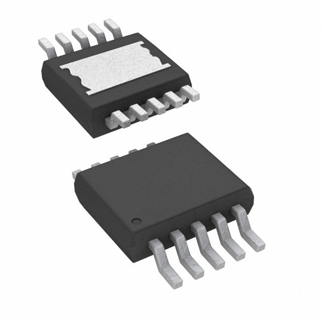


 工商网监
湘ICP备2023018690号
工商网监
湘ICP备2023018690号
