BLA1011-10
Avionics LDMOS transistor
Rev. 6 — 1 September 2015
Product data sheet
IMPORTANT NOTICE
Dear customer,
As of December 7th, 2015 BL RF Power of NXP Semiconductors will operate as
an independent company under the new trade name Ampleon, which will be used
in future data sheets together with new contact details.
In data sheets, where the previous Philips references is mentioned, please use
the new links as shown below.
http://www.philips.semiconductors.com use http://www.ampleon.com
http://www.semiconductors.philips.com use http://www.ampleon.com (Internet)
sales.addresses@www.semiconductors.philips.com use
http://www.ampleon.com/sales
The copyright notice at the bottom of each page (or elsewhere in the document,
depending on the version)
- © Koninklijke Philips Electronics N.V. (year). All rights reserved is replaced with:
- © Ampleon B.V. (year). All rights reserved. If you have any questions related to the data sheet, please contact our nearest
sales office (details via http://www.ampleon.com/sales).
Thank you for your cooperation and understanding,
Ampleon
�Philips Semiconductors
Product specification
Avionics LDMOS transistor
BLA1011-10
FEATURES
PINNING - SOT467C
• High power gain
PIN
DESCRIPTION
• Easy power control
1
drain
• Excellent ruggedness
2
gate
• Source on mounting base eliminates DC isolators,
reducing common mode inductance.
3
source, connected to flange
APPLICATIONS
1
• Avionics transmitter applications in the
1030 to 1090 MHz frequency range.
3
DESCRIPTION
2
Silicon N-channel enhancement mode lateral D-MOS
transistor encapsulated in a 2-lead flange package
(SOT467C) with a ceramic cap. The common source is
connected to the flange.
Top view
MBK584
Fig.1 Simplified outline (SOT467C).
QUICK REFERENCE DATA
RF performance at Th = 25 °C in a common source test circuit.
f
(MHz)
VDS
(V)
PL
(W)
Gp
(dB)
ηD
(%)
1030 to 1090
36
10
>15
>40
MODE OF OPERATION
Pulsed class-AB;
tp = 50 µs; δ = 2 %
ORDERING INFORMATION
PACKAGE
TYPE NUMBER
BLA1011-10
NAME
DESCRIPTION
VERSION
−
flanged LDMOST ceramic package; 2 mounting holes; 2 leads
SOT467C
LIMITING VALUES
In accordance with the Absolute Maximum Rating System (IEC 60134).
SYMBOL
PARAMETER
CONDITIONS
MIN.
MAX.
UNIT
VDS
drain-source voltage
−
75
V
VGS
gate-source voltage
−
±15
V
ID
drain current (DC)
−
2.2
A
Ptot
total power dissipation
−
25
W
Tstg
storage temperature
−65
+150
°C
Tj
junction temperature
−
200
°C
2003 Nov 19
Th ≤ 25 °C
2
�Philips Semiconductors
Product specification
Avionics LDMOS transistor
BLA1011-10
THERMAL CHARACTERISTICS
SYMBOL
PARAMETER
CONDITIONS
VALUE
UNIT
Zth(j-mb)
thermal impedance from junction to mounting base
Tmb = 25 °C; note 1
1.2
K/W
Rth(mb-h)
thermal resistance from mounting base to heatsink
note 2
0.55
K/W
MAX.
UNIT
Notes
1. Thermal impedance is determined under RF operating conditions with pulsed bias.
2. Typical value for SOT467C mounted with thermal compound and 0.6 Nm fastening torque.
CHARACTERISTICS
Tj = 25 °C unless otherwise specified.
SYMBOL
PARAMETER
CONDITIONS
MIN.
TYP.
V(BR)DSS
drain-source breakdown voltage
VGS = 0; ID = 0.7 mA
75
−
−
V
VGSth
gate-source threshold voltage
VDS = 10 V; ID = 20 mA
4
−
5
V
IDSS
drain-source leakage current
VGS = 0; VDS = 28 V
−
−
0.1
mA
IDSX
on-state drain current
VGS = VGSth + 9 V; VDS = 10 V 2.8
−
−
A
IGSS
gate leakage current
VGS = ±15 V; VDS = 0
−
−
40
nA
gfs
forward transconductance
VDS = 10 V; ID = 0.75 A
−
0.5
−
S
RDSon
drain-source on-state resistance
VGS = 10 V; ID = 0.75 A
−
1.2
−
Ω
APPLICATION INFORMATION
RF performance in a common source class-AB circuit. Th = 25 °C; Rth mb-h = 0.55 K/W unless otherwise specified.
MODE OF
OPERATION
f
(MHz)
VDS
(V)
IDQ
(mA)
PL
(W)
Gp
(dB)
ηD
(%)
tr
(ns)
tf
(ns)
PULSE DROOP
(dB)
Pulsed class-AB;
tp = 50 µs; δ = 2%
1030 to 1090
36
50
10
>15
>40
很抱歉,暂时无法提供与“BLA1011-10”相匹配的价格&库存,您可以联系我们找货
免费人工找货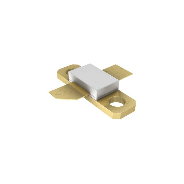


 工商网监
湘ICP备2023018690号
工商网监
湘ICP备2023018690号
