EK36
Evaluation Kit
APPLICABLE PARTS (SOLD SEPARATELY)
•
PA99 Power Amplifier
INTRODUCTION
This high-voltage Evaluation kit provides a robust PCB with ideal circuit layout and grounding in order to
evaluate the Apex PA99 linear power operational amplifier. With its high-voltage, modest package size, and
thermal sensing capabilities, the PA99 includes many considerations in its evaluation board. This ruggedized
testing platform utilizes many design techniques that make it easy to analyze the PA99 under a wide variety
of conditions. All necessary components (except DUT) are included in the kit.
This evaluation kit provides flexibility for modifying gain in both inverting and non-inverting mode, as well
as for use as a differential amplifier. There are also options for stability considerations such as isolation resistors, R-C snubber networks, feedback capacitors, noise gain compensation, and compensation capacitors.
DANGER
HIGH VOLTAGE
www.apexanalog.com
CAUTION
FIRE HAZARD
The non-insulated high Voltages that are present when
operating the evaluation kit constitute a risk of electric
shock, personal injury, death and/or ignition of fire.
The evaluation kit is intended for evaluation purposes only.
It shall only be operated in a designated, fully protected
test area by personnel qualified according to local requirements and labor laws to work with high-voltage circuits. It
shall never be operated unattended.
© Apex Microtechnology Inc.
All rights reserved
Oct 2016
EK36U Rev C
�EK36
Figure 1: EK Schematic
2
EK36U Rev C
�EK36
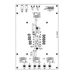
Figure 2: Board Layout
EK36U Rev C
3
�EK36
PARTS LIST
Reference
Manufacturer Part #
Description
QTY
RT1, RT2
PR03000205109JAC00
51 Ω, 3 W, 5%
2
RLIM1
MFR-25FBF52-32R4
32.4 Ω, 1/4W, 1%
1
RLIM2
MFR-25FBF52-33K2
33.2 kΩ, 1/4W, 1%
1
RFB2
RNX2002M00FKEL
2 MΩ, 5 W, 1%
1
RIN1
CMF5510K000FKEA
10 kΩ, 2.5 W, 1%
1
EVAL 83
Printed Circuit Board
1
CBP-1 TO CBP-10
2225WC223KAT1A
0.022 uF, 2.5 kV
10
CC
CC45SL3FD100JY
15 pF, 6kV
1
D3, D4
1N4148
Switching Diode
2
D1, D2
GP02-30-E3/54
Rectifier, 3kV
2
HS34
Heat Sink
1
TW21
Thermal Washer (Pack of 5 Pcs)
1
0284-0-15-15-16-27-10-0
Cage Jacks
12
146510CJ
BNC Connector, Pc Mount
2
571-0100
Horizontal Banana Jack
2
Resistors
Printed Circuit Boards
EVAL 83
Capacitors
Diodes
Hardware
4
108-0903-001
Vertical Banana Jack
6
91735A192
Screw, Panhead, #8-32 X 0.375”
4
2221
Standoff, 0.25" Hex, AL, #8-32 X 2"
4
91841A009
Nut, Hex #8-32
4
91735A151
Screw, Panhead, #6-32 X 0.75”
2
91841A007
Nut, Hex #6-32
2
90272A197
Screw, Panhead, #8-32 X 0.75"
4
99492A003
Spacer, Hex, Un-Threaded, #8 X 3/16"
4
TFT20024 NA005
Tubing, Teflon, #24 AWG, 6”
1
EK36U Rev C
�EK36
BEFORE YOU GET STARTED
•
•
•
•
•
•
Please refer to Application Note, AN01 for general operating conditions.
All Apex Microtechnology amplifiers should be handled using proper ESD precautions.
Always use the heat sink and thermal washer included in this kit.
Do not change the connections while the circuit is powered.
Initially set all power supplies to the minimum operations levels allowed in the device data sheet.
Check for oscillations after initial power up of board.
ASSEMBLY
During the assembly, please refer to the circuit schematics, assembly drawings, and the data sheet of the part
being used on the evaluation kit.
1. Note that each side of the circuit board is identified as either the component side or the DUT side. The
component side has the designators printed on that side.
2. All the components (except the cage jacks) are installed on the component side of the board and soldered
on the DUT side.
3. 12 high-voltage cage jacks are included in this kit. These should be installed on the DUT side and soldered
from the component side.
4. Mount capacitors CBP1 through CBP10. The capacitors provided in the kit do not have polarity, so they
may be installed in either direction.
5. Install diodes D1, D2, D3, and D4, as well as resistor RFB2 on the component side of the board. RFB3
should be shorted if no resistor is being used. Ensure that the orientation of the diodes match the circuit
schematic drawing.
6. Next install all the smaller components on the board, such as CC, RLIM1 and RLIM2, RT1 and RT2, and
RIN1. This is done because it becomes difficult to install a smaller part on the board once all the larger
components are installed. If noise gain compensation, capacitive feedback, or an output snubber network
are desired, these should be installed now.
7. An isolation resistor RISO1 can be installed if desired (for reactive loads). If not, RISO1 can be shorted
using an insulated piece of solid or stranded wire.
8. Mount six vertical banana jacks for P1, P2, P3, P4, P5, and P8. Drop the banana jacks into each slotted
hole, secure their position with the included nut, and solder a piece of 16 gauge wire to route the end of
each connector to their respective pads.
9. Mount the BNC connectors provided with the kit (146510CJ) and solder them to the board. Also solder
the two horizontal banana jacks (571-0100) to TMPA and TMPB.
10. 4 #8 hex stand offs (2221) are also provided with the kit. Install with 4 #8 x 0.375"screws (91735A192) on
the component side. Attach the standoffs to these screws on the corners of the board. Refer to the
assembly drawings while installing the standoffs.
11. Cut the Teflon tubing into 12 pieces, each of length 0.18” or 4.5 mm approximately. These pieces go onto
the pins of the power amplifier before inserting it into the board. This is done to insulate the pins from
the heat sink and make sure that the amplifier is tightly fixed into the jacks. An Exacto knife works well for
this.
Note: The Teflon pieces should not be longer than the suggested length. If the pieces are longer, they
may interfere in the seating of the part to the board and create a gap between the heat sink and
the part body.
12. Five thermal washers (TW21) are provided with the kit. The thermal washer is used between the part and
the heatsink (HS34). A new washer must be used for each mounting. Place the amplifier into the heatsink
with a thermal washer in between. Secure this attachment with a #6 x 0.75" screw (91735A151) and
matching nut on either side of the amplifier.
EK36U Rev C
5
�EK36
13. Insert the pins of the amplifier-heatsink assembly into the cage jacks. Be sure to have pin 1 (closest to the
notch on the amplifier package) pointing toward the input BNC connectors. Also be sure not to bend the
pins while placing them into the jacks. Perform a visual inspection to make sure all pins are inserted into
the jacks without bending.
14. Place a hex spacer (99492A003) between one corner of the heatsink and the evaluation board. Place a #8
x 0.75" screw (90272A197) through the slot on the heatsink and tighten with a #8 nut on the component
side. Repeat for all four corners of the heatsink. Refer to the assembly drawings for the correct way to
attach the heat sink.
15. Position the board so the component side is facing up. Hook up power supply and signals as necessary.
Connect the temperature jacks to a diode voltage reading multimeter. The amplifier is now ready for testing.
6
EK36U Rev C
�EK36
Figure 3: Evaluation Kit Assembly (Top View)
EK36U Rev C
7
�EK36
Figure 4: Evaluation Kit Assembly (Bottom View)
8
EK36U Rev C
�EK36
TEST ASSEMBLY
EQUIPMENT NEEDED
1.
2.
3.
4.
Power supply
Function Generator
Oscilloscope
Multi-meter
TEST SETUP
Connect the power supply to the banana jacks. For an inverting configuration, connect the BNC cable
from the function generator to the BNC connector marked - VIN, mounted on the board. For non-inverting
configurations, use + VIN. Connect the load to the banana jacks marked OUT (0 for direct output, 1 for isolation resistor output) and COM. Refer to the amplifier datasheet for typical values of input voltage, frequency
and supply voltage. Input and output waveforms can be checked on an oscilloscope by connecting it to the
test points mounted on the board. Begin the test with minimum values of input and supply voltage. Please
maintain caution while operating at high voltages.
Note: For added precaution, power on the circuit with the amplifier removed. Check the voltage at each
cage jack without the DUT, for correct voltage / signal at each respective pin. Once this is done,
switch off the supply and plug in the DUT.
CAUTION
This evaluation kit may be subjected to high voltages. Please maintain caution while operating
the kit at high voltages.
TEST RESULTS
Figure 5 shows input (magenta waveform) and output (yellow waveform) waveforms for a PA99 power
amplifier with no load. The part was tested for an input voltage of 10V p-p, at 1 kHz frequency, and at an
inverting gain of 200. The supply voltage is set at + 1250 Volts.
Figure 5: PA99 Test Waveforms
Vout
Vin
EK36U Rev C
9
�EK36
NEED TECHNICAL HELP? CONTACT APEX SUPPORT!
For all Apex Microtechnology product questions and inquiries, call toll free 800-546-2739 in North America. For
inquiries via email, please contact apex.support@apexanalog.com. International customers can also request
support by contacting their local Apex Microtechnology Sales Representative. To find the one nearest to you,
go to www.apexanalog.com
IMPORTANT NOTICE
Apex Microtechnology, Inc. has made every effort to insure the accuracy of the content contained in this document. However, the information is
subject to change without notice and is provided "AS IS" without warranty of any kind (expressed or implied). Apex Microtechnology reserves the right
to make changes without further notice to any specifications or products mentioned herein to improve reliability. This document is the property of
Apex Microtechnology and by furnishing this information, Apex Microtechnology grants no license, expressed or implied under any patents, mask
work rights, copyrights, trademarks, trade secrets or other intellectual property rights. Apex Microtechnology owns the copyrights associated with the
information contained herein and gives consent for copies to be made of the information only for use within your organization with respect to Apex
Microtechnology integrated circuits or other products of Apex Microtechnology. This consent does not extend to other copying such as copying for
general distribution, advertising or promotional purposes, or for creating any work for resale.
APEX MICROTECHNOLOGY PRODUCTS ARE NOT DESIGNED, AUTHORIZED OR WARRANTED TO BE SUITABLE FOR USE IN PRODUCTS USED FOR LIFE
SUPPORT, AUTOMOTIVE SAFETY, SECURITY DEVICES, OR OTHER CRITICAL APPLICATIONS. PRODUCTS IN SUCH APPLICATIONS ARE UNDERSTOOD TO BE
FULLY AT THE CUSTOMER OR THE CUSTOMER’S RISK.
Apex Microtechnology, Apex and Apex Precision Power are trademarks of Apex Microtechnology, Inc. All other corporate names noted herein may be
trademarks of their respective holders.
10
EK36U Rev C
�


 工商网监
湘ICP备2023018690号
工商网监
湘ICP备2023018690号
