X7S Dielectric
General Specifications
GENERAL DESCRIPTION
X7S formulations are called “temperature stable” ceramics and fall into EIA Class II materials. Its temperature
variation of capacitances within ±22% from –55°C to +125°C. This capacitance change is non-linear.
Capacitance for X7S varies under the influence of electrical operating conditions such as voltage and frequency.
X7S dielectric chip usage covers the broad spectrum of industrial applications where known changes in capacitance
due to applied voltages are acceptable.
PART NUMBER (SEE PAGE 4 FOR COMPLETE PART NUMBER EXPLANATION)
1206
Z
Z
105
M
A
T
2
A
Size
(L” x W”)
Voltage
Dielectric
Capacitance
Capacitance
Failure
Rate
A = N/A
Terminations
T = Plated Ni
and Sn
Packaging
2 = 7” Reel
4 = 13” Reel
Special
Code
A = Std.
Product
4 = 4V
Z = X7S
Code (In pF)
Tolerance
6 = 6.3V
2 Sig. Digits +
K = ±10%
Z = 10V
Number of
M = ± 20%
Y = 16V
Zeros
3 = 25V
5 = 50V
1 = 100V
2 = 200V
NOTE: Contact factory for availability of Tolerance Options for Specific Part Numbers.
X7S Dielectric
Typical Temperature Coefficient
Capacitance vs. Frequency
10
+30
+20
Capacitance
0
-5
-10
-15
%
% Cap Change
5
-20
-25
-60 -40 -20
0 20 40 60 80 100 120 140
Temperature (°C)
0
-10
-20
-30
1KHz
10 KHz
100 KHz
10
0.01
10
Frequency, MHz
1000
100
0
0
20
40
0.1
1
100
10
Frequency, MHz
100
120
Variation of Impedance with Chip Size
Impedance vs. Frequency
100,000 pF - X7S
10
1,000
1.0
0.1
.01
1
10
100
1,000
Frequency, MHz
The Important Information/Disclaimer is incorporated in the catalog where these specifications came from or
available online at www.avx.com/disclaimer/ by reference and should be reviewed in full before placing any order.
101316
80
1206
0805
1210
1.0
.01
60
Temperature °C
Impedance,
Impedance,
Impedance,
100
1,000
1206
0805
1210
10,000 pF
0.10
10 MHz
Variation of Impedance with Chip Size
Impedance vs. Frequency
10,000 pF - X7S
1,000 pF
1.00
1 MHz
Insulation Resistance vs Temperature
10,000
Frequency
Variation of Impedance with Cap Value
Impedance vs. Frequency
1,000 pF vs. 10,000 pF - X7S
0805
10.00
+10
Insulation Resistance (Ohm-Farads)
TYPICAL ELECTRICAL CHARACTERISTICS
23
�X7S Dielectric
Specifications and Test Methods
Parameter/Test
Operating Temperature Range
Capacitance
Dissipation Factor
Insulation Resistance
Dielectric Strength
Appearance
Resistance to
Flexure
Stresses
Capacitance
Variation
Dissipation
Factor
Insulation
Resistance
Solderability
Appearance
Resistance to
Solder Heat
Thermal Shock
Load Life
Load
Humidity
Capacitance
Variation
Dissipation
Factor
Insulation
Resistance
Dielectric
Strength
Appearance
Capacitance
Variation
Dissipation
Factor
Insulation
Resistance
Dielectric
Strength
Appearance
Capacitance
Variation
Dissipation
Factor
Insulation
Resistance
Dielectric
Strength
Appearance
Capacitance
Variation
Dissipation
Factor
Insulation
Resistance
Dielectric
Strength
24
X7S Specification Limits
-55ºC to +125ºC
Within specified tolerance
≤ 5.0% for ≥ 100V DC rating
≤ 5.0% for ≥ 25V DC rating
≤ 10.0% for ≥ 10V DC rating
≤ 10.0% for ≤ 10V DC rating
Contact Factory for DF by PN
100,000MΩ or 1000MΩ - μF,
whichever is less
No breakdown or visual defects
No defects
≤ ±12%
Measuring Conditions
Temperature Cycle Chamber
Freq.: 1.0 kHz ± 10%
Voltage: 1.0Vrms ± .2V
For Cap > 10 μF, 0.5Vrms @ 120Hz
Charge device with rated voltage for
120 ± 5 secs @ room temp/humidity
Charge device with 250% of rated voltage for
1-5 seconds, w/charge and discharge current
limited to 50 mA (max)
Deflection: 2mm
Test Time: 30 seconds
Meets Initial Values (As Above)
≥ Initial Value x 0.3
≥ 95% of each terminal should be covered
with fresh solder
Dip device in eutectic solder at 230 ± 5ºC
for 5.0 ± 0.5 seconds
No defects,
很抱歉,暂时无法提供与“12106Z226KAT2A”相匹配的价格&库存,您可以联系我们找货
免费人工找货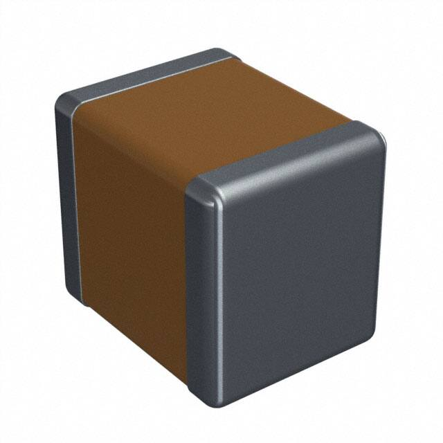


 工商网监
湘ICP备2023018690号
工商网监
湘ICP备2023018690号
