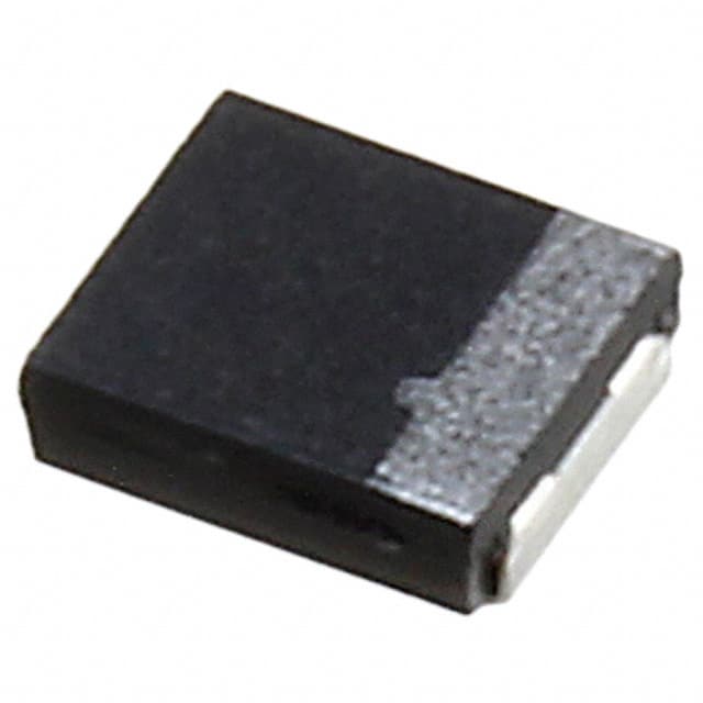
F92 Series
Resin-Molded Chip, Low Profile J-Lead
FEATURES
• Compliant to the RoHS2 directive 2011/65/EU
• SMD J-lead
• Low profile case sizes
LEAD-FREE COMPATIBLE
COMPONENT
APPLICATIONS
• Handheld electronics
• USB accessories
CASE DIMENSIONS: millimeters (inches)
Code EIA Code EIA Metric
A
1206
3216-12
B
1311
3428-12
P
0805
2012-12
L
L
3.20 ± 0.20
(0.126 ± 0.008)
3.40 ± 0.20
(0.134 ± 0.008)
2.00 ± 0.20
(0.079 ± 0.008)
W1
W1
1.60 ± 0.20
(0.063 ± 0.008)
2.80 ± 0.20
(0.110 ± 0.008)
1.25 ± 0.10
(0.049 ± 0.004)
P CASE
W2
H
1.10 ± 0.10
(0.043 ± 0.004)
1.10 ± 0.10
(0.043 ± 0.004)
1.10 ± 0.10
(0.043 ± 0.004)
S
0.80 ± 0.20
(0.031 ± 0.008)
0.80 ± 0.20
(0.031 ± 0.008)
0.50 ± 0.20
(0.020 ± 0.008)
MARKING
H
S
W2
1.20 ± 0.10
(0.047 ± 0.004)
2.30 ± 0.10
(0.091 ± 0.004)
0.90 ± 0.10
(0.035 ± 0.004)
A CASE
*Rated Capacitance
Code
Rated Voltage
Code
4V
6.3V
10V
16V
20V
25V
G
J
A
Rated Capacitance
(µF)
22
10V
G 226
AS
S
B CASE
Rated Capacitance
Code
Rated Voltage
Code
C
D
E
35V
Rated Voltage
(V)
V
*Capacitance code of “P” case products are as shown below.
HOW TO ORDER
F92 0J
106
Type
Rated
Voltage
Capacitance
Code
pF code: 1st two digits
represent significant figures,
3rd digit represents multiplier
(number of zeros to follow)
M
P
ⵧ
LZT
Tolerance
K = ±10%
M = ±20%
Case
Size
See
table
above
Packaging
See Tape & Reel
Packaging Section
Specification
Suffix
Rated temperature
60ºC only
TECHNICAL SPECIFICATIONS
Category Temperature Range:
Rated Temperature:
Capacitance Tolerance:
Dissipation Factor:
ESR 100kHz:
Leakage Current:
Capacitance Change By Temperature
26
-55 to +125°C
+85°C
±20%, ±10% at 120Hz
Refer to next page
Refer to next page
After 1 minute’s application of rated voltage, leakage current at 20°C
is not more than 0.01CV or 0.5μA, whichever is greater.
After 1 minute’s application of rated voltage, leakage current at 85°C
is not more than 0.1CV or 5μA, whichever is greater.
After 1 minute’s application of derated voltage, leakage current at 125°C
is not more than 0.125CV or 6.3μA, whichever is greater.
P Case
A, B Case
+20% Max. at +125ºC
+15% Max. at +125°C
+15% Max. at +85ºC
+10% Max. at +85°C
-15% Max. at -55ºC
-10% Max. at -55°C
040919
�F92 Series
Resin-Molded Chip, Low Profile J-Lead
CAPACITANCE AND RATED VOLTAGE RANGE
(LETTER DENOTES CASE SIZE)
Capacitance
µF
Code
0.22
224
0.33
334
0.47
474
0.68
684
1.0
105
1.5
155
2.2
225
3.3
335
4.7
475
6.8
685
10
106
15
156
22
226
33
336
47
476
68
686
100
107
150
157
220
227
4V (0G)
P
P
P
A/P
P
A/P(M)
A/P(M)
A/B
A(M)/B
A(M)/B
B(M)
6.3V (0J)
P
P
P
P
A/P
A/P(M)
A/P(M)
A/B
A/B
Rated Voltage
10V (1A)
16V (1C)
P
P
P
A/P
A/P
A/P
A/P(M)
A
A/B
B
B
P
P
P
P
A/P
A
A/B
B
A/B
B
A(M)**/B
20V (1D)
25V (1E)
A/P
A
A/P
A
A
35V (1V)
A
A
A
A/P
A
A/B
B
B
A(M)/B
A/B
B
*Cap
Code
J
N
S
W
A
E
J
N
S
w
a
e
J
n
s
w
A
E
J
Released ratings (M tolerance only)
**Rated temperature 60ºC only. Please contact AVX when you need detail spec.
Please contact to your local AVX sales office when these series are being designed in your application.
040919
27
�F92 Series
Resin-Molded Chip, Low Profile J-Lead
RATINGS & PART NUMBER REFERENCE
AVX
Part No.
Case
Size
Capacitance
(μF)
Rated
Voltage
(V)
DCL
(μA)
DF
@ 120Hz
(%)
F920G335#PA
F920G475#PA
F920G685#PA
F920G106#AA
F920G106#PA
F920G156#PA
F920G226#AA
F920G226MPA
F920G336#AA
F920G336MPA
F920G476#AA
F920G476#BA
F920G686MAA
F920G686#BA
F920G107MAA
F920G107#BA
F920G157MBA
P
P
P
A
P
P
A
P
A
P
A
B
A
B
A
B
B
3.3
4.7
6.8
10
10
15
22
22
33
33
47
47
68
68
100
100
150
4
4
4
4
4
4
4
4
4
4
4
4
4
4
4
4
4
0.5
0.5
0.5
0.5
0.5
0.6
0.9
0.9
1.3
1.3
1.9
1.9
2.7
2.7
4.0
4.0
6.0
8
8
10
8
10
10
12
20
12
20
18
12
25
18
30
18
25
F920J225#PA
F920J335#PA
F920J475#PA
F920J685#PA
F920J106#AA
F920J106#PA
F920J156#AA
F920J156MPA
F920J226#AA
F920J226MPA
F920J336#AA
F920J336#BA
F920J476#AA
F920J476#BA
F920J107MAALZT
F920J107#BA
P
P
P
P
A
P
A
P
A
P
A
B
A
B
A
B
2.2
3.3
4.7
6.8
10
10
15
15
22
22
33
33
47
47
100
100
6.3
6.3
6.3
6.3
6.3
6.3
6.3
6.3
6.3
6.3
6.3
6.3
6.3
6.3
6.3
6.3
0.5
0.5
0.5
0.5
0.6
0.6
0.9
0.9
1.4
1.4
2.1
2.1
3.0
3.0
63.0
6.3
F921A105#PA
F921A155#PA
F921A225#PA
F921A335#AA
F921A335#PA
F921A475#AA
F921A475#PA
F921A685#AA
F921A685#PA
F921A106#AA
F921A106MPA
F921A156#AA
F921A226#AA
F921A226#BA
F921A336#BA
F921A476#BA
P
P
P
A
P
A
P
A
P
A
P
A
A
B
B
B
1
1.5
2.2
3.3
3.3
4.7
4.7
6.8
6.8
10
10
15
22
22
33
47
10
10
10
10
10
10
10
10
10
10
10
10
10
10
10
10
0.5
0.5
0.5
0.5
0.5
0.5
0.5
0.7
0.7
1.0
1.0
1.5
2.2
2.2
3.3
4.7
F921C474#PA
F921C684#PA
F921C105#PA
F921C155#PA
F921C225#AA
F921C225#PA
F921C335#AA
F921C475#AA
F921C475#BA
F921C685#BA
F921C106#AA
F921C106#BA
F921C226#BA
P
P
P
P
A
P
A
A
B
B
A
B
B
0.47
0.68
1
1.5
2.2
2.2
3.3
4.7
4.7
6.8
10
10
22
16
16
16
16
16
16
16
16
16
16
16
16
16
0.5
0.5
0.5
0.5
0.5
0.5
0.5
0.8
0.8
1.1
1.6
1.6
3.5
F921D474#AA
F921D474#PA
F921D684#AA
F921D105#AA
F921D105#PA
F921D155#AA
F921D225#AA
A
P
A
A
P
A
A
0.47
0.47
0.68
1
1
1.5
2.2
20
20
20
20
20
20
20
0.5
0.5
0.5
0.5
0.5
0.5
0.5
ESR
@ 100kHz
(Ω)
25ºC
60ºC
85ºC
125ºC
*1
ΔC/C
(%)
MSL
50
71
71
122
71
77
146
77
146
87
146
210
146
224
146
240
240
–
–
–
–
–
–
–
–
–
–
–
–
–
–
–
–
–
45
64
64
110
64
70
132
70
132
78
132
189
132
201
132
216
216
20
28
28
49
28
31
59
31
59
35
59
84
59
89
59
96
96
*
*
*
*
*
*
*
*
*
*
*
*
±15
*
±15
*
±15
1
1
1
1
1
1
1
1
1
1
1
1
1
1
1
1
1
50
50
71
71
122
71
122
71
146
77
146
210
146
210
141
240
–
–
–
–
–
–
–
–
–
–
–
–
–
–
127
–
45
45
64
64
110
64
110
64
132
70
132
189
132
189
–
216
20
20
28
28
49
28
49
28
59
31
59
84
59
84
57
96
*
*
*
*
*
*
*
*
*
*
*
*
±15
*
±20
±15
1
1
1
1
1
1
1
1
1
1
1
1
1
3
3
1
50
50
50
93
50
122
71
122
71
122
71
122
122
199
199
199
–
–
–
–
–
–
–
–
–
–
–
–
–
–
–
–
45
45
45
83
45
110
64
110
64
110
64
110
110
179
179
179
20
20
20
37
20
49
28
49
28
49
28
49
49
79
79
79
*
*
*
*
*
*
*
*
*
*
*
*
±15
*
*
±15
1
1
1
1
1
1
1
1
1
1
1
1
1
3
1
1
39
50
50
50
93
50
93
93
158
158
93
194
194
–
–
–
–
–
–
–
–
–
–
–
–
–
35
45
45
45
83
45
83
83
142
142
83
174
174
15
20
20
20
37
20
37
37
63
63
37
77
77
*
*
*
*
*
*
*
*
*
*
±15
*
±15
1
1
1
1
1
1
1
1
1
1
1
1
1
77
39
77
77
39
90
93
–
–
–
–
–
–
–
70
35
70
70
35
81
83
31
15
31
31
15
36
37
*
*
*
*
*
*
*
1
1
1
1
1
1
1
100kHz RMS Current (mA)
4 Volt
28
12.0
6.0
6.0
4.0
6.0
5.0
2.8
5.0
2.8
4.0
2.8
1.7
2.8
1.5
2.8
1.3
1.3
6.3 Volt
12.0
8
12.0
8
6.0
8
6.0
10
4.0
8
6.0
10
4.0
8
6.0
10
2.8
12
5.0
20
2.8
12
1.7
12
2.8
18
1.7
12
3.0
40
1.3
20
10 Volt
12.0
8
12.0
8
12.0
8
7.0
6
12.0
8
4.0
6
6.0
8
4.0
6
6.0
8
4.0
8
6.0
14
4.0
8
4.0
14
1.9
8
1.9
12
1.9
18
16 Volt
20.0
8
12.0
8
12.0
8
12.0
8
7.0
6
12.0
8
7.0
6
7.0
6
3.0
6
3.0
6
7.0
8
2.0
6
2.0
12
20 Volt
10.0
4
20.0
8
10.0
4
10.0
4
20.0
8
7.4
6
7.0
6
040919
�F92 Series
Resin-Molded Chip, Low Profile J-Lead
RATINGS & PART NUMBER REFERENCE
AVX
Part No.
Case
Size
Capacitance
(μF)
Rated
Voltage
(V)
DCL
(μA)
DF
@ 120Hz
(%)
ESR
@ 100kHz
(Ω)
25ºC
60ºC
85ºC
125ºC
*1
ΔC/C
(%)
MSL
F921D475MAA
F921D475#BA
F921D106#BA
A
B
B
4.7
4.7
10
20
20
20
0.9
0.9
2.0
10
6
8
7.0
3.0
3.0
93
158
158
–
–
–
83
142
142
37
63
63
±10
*
±10
1
1
1
F921E105#AA
F921E105#PA
F921E225#AA
F921E225#BA
F921E475#AA
F921E475#BA
A
P
A
B
A
B
1
1
2.2
2.2
4.7
4.7
25
25
25
25
25
25
0.5
0.5
0.6
0.6
1.2
1.2
6
8
8
6
10
6
77
39
77
137
93
158
–
–
–
–
–
–
70
35
70
123
83
142
31
15
31
55
37
63
*
*
±15
*
±10
*
1
1
1
1
1
1
F921V224#AA
F921V334#AA
F921V474#AA
F921V105#AA
F921V225#BA
F921V335#BA
A
A
A
A
B
B
0.22
0.33
0.47
1
2.2
3.3
35
35
35
35
35
35
0.5
0.5
0.5
0.5
0.8
1.2
77
77
77
77
137
137
–
–
–
–
–
–
70
70
70
70
123
123
31
31
31
31
55
55
*
*
*
*
±10
±10
1
1
1
1
1
1
25 Volt
10.0
20.0
10.0
4.0
7.0
3.0
35 Volt
4
10.0
4
10.0
4
10.0
6
10.0
6
4.0
10
4.0
*1: ΔC/C Marked “*”
Item
Damp Heat
Temperature cycles
Resistance soldering heat
Surge
Endurance
P Case (%)
±20
±10
±10
±10
±10
A, B Case (%)
±10
±5
±5
±5
±10
100kHz RMS Current (mA)
#: "M" for ±20% tolerance, "K" for ± 10% tolerance. When you need K tolerance for the part numbers
which have M tolerance only, please contact to your local AVX sales office.
Moisture Sensitivity Level (MSL) is defined according to J-STD-020.
We can consider the type of compliance to AEC-Q200.
Please contact to your local AVX sales office
when these series are being designed in your application.
QUALIFICATION TABLE
TEST
Damp Heat
(Steady State)
Temperature Cycles
Resistance to
Soldering Heat
Surge
Endurance
Shear Test
Terminal Strength
040919
F92 series (Temperature range -55ºC to +125ºC)
Condition
P Case
A, B Case
At 40°C, 90 to 95% R.H., 500 hours (No voltage applied)
Capacitance Change ........... Refer to page 28 (*1)
Refer to page 28 (*1)
Dissipation Factor ................ 150% or less than the initial specified value
Initial specified value or less
Leakage Current .................. Initial specified value or less
Initial specified value or less
-55°C / +125°C, 30 minutes each, 5 cycles
Capacitance Change ........... Refer to page 28 (*1)
Refer to page 28 (*1)
Dissipation Factor ................ 150% or less than the initial specified value
Initial specified value or less
Leakage Current .................. Initial specified value or less
Initial specified value or less
10 seconds reflow at 260°C, 5 seconds immersion at 260°C.
Capacitance Change ........... Refer to page 28 (*1)
Refer to page 28 (*1)
Dissipation Factor ................ 150% or less than the initial specified value
Initial specified value or less
Leakage Current .................. Initial specified value or less
Initial specified value or less
After application of surge voltage in series with a 33Ω (For “P” case: 1kΩ) resistor at the rate of 30 seconds ON, 30 seconds
OFF, for 1000 successive test cycles at 85ºC, capacitors shall meet the characteristic requirements in the table above.
Capacitance Change ........... Refer to page 28 (*1)
Refer to page 28 (*1)
Dissipation Factor ................ 150% or less than the initial specified value
Initial specified value or less
Leakage Current .................. Initial specified value or less
Initial specified value or less
After 2000 hours’ application of rated voltage in series with a 3Ω resistor at 85°C, or derated voltage in series with a 3Ω
resistor at 125°C, capacitors shall meet the characteristic requirements in the table above.
Capacitance Change ........... Refer to page 28 (*1)
Refer to page 28 (*1)
Dissipation Factor ................ 150% or less than the initial specified value
Initial specified value or less
Leakage Current .................. Initial specified value or less
Initial specified value or less
After applying the pressure load of 5N for 10±1 seconds horizontally to the center of capacitor side body
which has no electrode and has been soldered beforehand on a substrate, there shall be found neither
exfoliation nor its sign at the terminal electrode.
Keeping a capacitor surface-mounted on a substrate upside down and supporting the substrate at
both of the opposite bottom points 45mm apart from the center of capacitor, the pressure strength is
applied with a specified jig at the center of substrate so that the substrate may bend by 1mm as
illustrated. Then, there shall be found no remarkable abnormality on the capacitor terminals.
29
�F92 Series
Resin-Molded Chip, Low Profile J-Lead
AVX SOLID ELECTROLYTIC CAPACITOR ROADMAP
SERIES LINE UP: CONVENTIONAL SMD MnO2
30
040919
�
很抱歉,暂时无法提供与“F920J476MBA”相匹配的价格&库存,您可以联系我们找货
免费人工找货- 国内价格 香港价格
- 2500+1.206992500+0.14608
- 国内价格 香港价格
- 1+5.787641+0.70047
- 10+3.8739810+0.46886
- 50+3.0823850+0.37306
- 100+2.54594100+0.30813
- 500+1.98906500+0.24073
- 1000+1.690711000+0.20463


 工商网监
湘ICP备2023018690号
工商网监
湘ICP备2023018690号
