PL
IA
N
T
Features
M
■ Miniature package for design flexibility
*R
oH
S
CO
■ Long operating life
■ Conductive plastic element
■ Bushing or PC board mount
■ Quadrature output
■ RoHS compliant*
3315 - 9 mm Square Sealed Incremental Encoder
Electrical Characteristics
Output..................................................................................2-bit quadrature code, Channel A leads Channel B electrically turning clockwise (CW)
Closed Circuit Resistance ...............................................................................................................................................................5 ohms maximum
Contact Rating........................................................................................................................................................................... TTL compatible loads
Insulation Resistance (500 VDC) .......................................................................................................................................1,000 megohms minimum
Dielectric Withstanding Voltage
Sea Level ..................................................................................................................................................................................900 VAC minimum
Electrical Travel ......................................................................................................................................................................................... Continuous
Contact Bounce .................................................................................................................................................................... 5 milliseconds maximum
RPM (Operating) ...................................................................................................................................................................................120 maximum
Environmental Characteristics
Operating Temperature Range.........................................................................................................................-40 °C to +125 °C (-40 °F to +257 °F)
Storage Temperature Range ............................................................................................................................ -55 ºC to +125 ºC (-67 °F to +257 °F)
Humidity .................................................................................................................................................... MIL-STD-202, Method 103B, Condition B
Vibration ...............................................................................................................................................................................................................30 G
Contact Bounce ..............................................................................................................................................................5.0 millisecond maximum
Shock .................................................................................................................................................................................................................100 G
Contact Bounce ..............................................................................................................................................................5.0 millisecond maximum
Rotational Life ..................................................................................................................................................................... 100,000 cycles @ 6 PPR
25,000 cycles @ 16 PPR
IP Rating .............................................................................................................................................................................................................. IP 67
Mechanical Characteristics
Mechanical Angle .............................................................................................................................................................................360 ° Continuous
Running Torque .........................................................................................................................................................3.53 N-cm (5 oz.-in.) maximum
Mounting Torque
Plastic Bushing ..................................................................................................................................................45.19 N-cm (4.0 lb.-in.) maximum
Metal Bushing.........................................................................................................................................................79 N-cm (7.0 lb.-in.) maximum
Weight .............................................................................................................................................................................................. 4.5 gm (0.15 oz.)
Terminals .............................................................................................................................................................................................Solderable pins
Soldering Condition
Manual Soldering ..................................... 96.5Sn/3.0Ag/0.5Cu solid wire or no-clean rosin cored wire; 370 °C (700 °F) max. for 3 seconds
Wave Soldering .............................................................. 96.5Sn/3.0Ag/0.5Cu solder with no-clean flux; 260 °C (500 °F) max. for 5 seconds
Wash Processes ..............................................For recommended wash processes, please refer to http://www.bourns.com/pdfs/sldclen.pdf
Marking.................................................................................................................................Manufacturer’s trademark, part number, and date code
Hardware .................................... One lockwasher and one mounting nut are shipped with each encoder, except where noted in the part number.
Suggested Incremental Control Diagram
7
9
Quadrature Output Table
CW
(CUSTOMER LOGIC CIRCUITRY)
Channel A
DIRECTION
5 ms DELAY
DEBOUNCE
(MC 14490)
DECODE
LOGIC
UP/DOWN
COUNTER
MAGNITUDE
BINARY
OUTPUT
Channel B
Channel C
CCW
WARNING Cancer and Reproductive Harm - www.P65Warnings.ca.gov
*RoHS Directive 2015/863, Mar 31, 2015 and Annex.
Specifications are subject to change without notice.
Users should verify actual device performance in their specific applications.
The products described herein and this document are subject to specific legal disclaimers as set forth on the last page of this document, and at www.bourns.com/docs/legal/disclaimer.pdf.
�3315 - 9 mm Square Sealed Incremental Encoder
How to Order
3315 Y - 0 0 1 - 006 L
Model Number Designator
3315 = 9 mm Encoder
Terminal Style Designator
C = In-line Straight Terminals Side Exit
R = In-line Terminals Rear Exit
P = 5.08 mm x 2.54 mm Triangular Pattern Rear Exit
Y = 5.08 mm x 5.08 mm Triangular Pattern Rear Exit
Shaft End Designator
0 = Shaft End Slotted
1 = Shaft End Flatted
Shaft Length Designator
0 = 12.7 mm FMS Long Plastic Shaft (Available w/bushing only)
1 = 19.05 mm FMS Long Plastic Shaft (Available w/bushing only)
2 = 5.59 mm FMS (Bushingless version only)
Bushing Designator
1 = 6.35 mm x 6.35 mm Plastic
2 = 6.35 mm x 6.35 mm Ni Plated Brass
5 = Bushingless (Board Level)
Pulses per Revolution Code
006 = 6 PPR
016 = 16 PPR
RoHS Identifier
L = Compliant
Specifications are subject to change without notice.
Users should verify actual device performance in their specific applications.
The products described herein and this document are subject to specific legal disclaimers as set forth on the last page of this document, and at www.bourns.com/docs/legal/disclaimer.pdf.
�3315 - 9 mm Square Sealed Incremental Encoder
Product Dimensions
3315C-001
COMMON DIMENSIONS
3315-001
3315Y-001
9.53 ± .25
(.375 ± .010)
C
Plastic Bushing
Slotted Shaft
9.53 ± .25
(.375 ± .010)
9.53 ± .25
A (.375 ± .010)
B
9.53 ± .25
(.375 ± .010)
.51 ± .05
DIA.
(.020 ± .002)
SOLDER PLATED
COPPER PINS
B
B
C
5.97 ± .89
(.235 ± .035)
A
2.54 ± .25
(.100 ± .010)
.391 ± .38
(.154 ± .015)
A
C
3315P-001
4.83 ± .25
(.190 ± .010)
4.75 MIN. FULL
(.187) THREAD
5.18 ± .38
(.204 ± .015)
6.35 ± .08
(.250 ± .003)
MOUNTING
DIA.
COMMON DIMENSIONS
3315C-101
2.54 ± .25
(.100 ± .010)
R
.76 ± .25
DEEP
(.030 ± .010)
5.97 ± .89
(.235 ± .035)
3315R-001
4.78
(.188)
2.54 ± .25
(.100 ± .010)
4.83
(.190)
12.70 ± .64
(.500 ± .025)
FROM MOUNTING
SURFACE
A
2.54 ± .25
(.100 ± .010)
DIMENSIONS:
2.54 ± .25
(.100 ± .010)
4.78
(.188)
6.35 ± .08
(.250 ± .003)
MOUNTING DIA.
5.97 ± .89
(.235 ± .035)
.51
4 PLACES
(.020)
MOUNTING HOLE PATTERN
1.70 ± 0.03
(.067 ± .001)
DIA.
MOUNTING
SURFACE
2.39
(.094)
C
B
.38
(.015)
MIN.
STANDOFF
Plastic Flatted Shaft
4.83 ± .38
(.190 ± .015)
.76 ± .05 X .76
HIGH
(.030 ± .002 X .030)
ANTI-ROTATION
BOSS
7.62
(.300)
DIA. MOUNTING
SURFACE
2.54 ± .25
(.100 ± .010)
2.54 ± .25
(.100 ± .010)
ADJUSTMENT SLOT
.64 ± .10
WIDE
(.025 ± .004)
X
2.54 ± .38
(.100 ± .015)
A 9.53 ± .25
(.375 ± .010)
B
6.35
(.250)
12.70 ± .64
(.500 ± .025)
5.97 ± .89
(.235 ± .035)
9.53 ± .25
(.375 ± .010)
C
DIA.
3.18 ± .05
(.125 ± .002)
2.54 ± .25
(.100 ± .010)
5.08 ± .25
(.200 ± .010)
2.54 ± .25
(.100 ± .010)
1/4-32 UNEF-2A
THREADED PLASTIC
BUSHING
MOUNTING
SURFACE
.38
(.015)
MIN.
STANDOFF
2.54 ± .25
(.100 ± .010)
MM
(INCHES)
6.53 ± 0.03
(.257 ± .001)
DIA.
Specifications are subject to change without notice.
Users should verify actual device performance in their specific applications.
The products described herein and this document are subject to specific legal disclaimers as set forth on the last page of this document, and at www.bourns.com/docs/legal/disclaimer.pdf.
�3315 - 9 mm Square Sealed Incremental Encoder
Product Dimensions
3315P-101
COMMON DIMENSIONS
C
3315P-002
3315-002
C
Metal Bushing
A
B
A
B
9.53 ± .25
(.375 ± .010)
2.54 ± .25
(.100 ± .010)
2.54 ± .25
(.100 ± .010)
9.53 ± .38
(.375 ± .015)
5.97 ± .89
(.235 ± .035)
2.54 ± .25
(.100 ± .010)
.51 ± .05
DIA.
(.020 ± .002)
SOLDER PLATED
COPPER PINS
2.54 ± .25
(.100 ± .010)
4.83 ± .38
(.190 ± .015)
3315R-101
5.97 ± .89
(.235 ± .035)
2.54 ± .25
(.100 ± .010)
1/4-32 UNEF-2A
THREADED PLASTIC
BUSHING
MOUNTING
SURFACE
C
.38
(.015)
MIN.
STANDOFF
A
B
2.54 ± .25
(.100 ± .010)
2.54 ± .25
(.100 ± .010)
5.97 ± .89
(.235 ± .035)
5.11 ± .25
(.201 ± .010)
4.83 ± .38
(.190 ± .015)
3315R-002
6.35 ± .08
(.250 ± .003)
MOUNTING DIA.
5.97 ± .89
(.235 ± .035)
3.18 ± .05
(.125 ± .002)
DIA.
2.54 ± .38
(.100 ± .015)
6.35
(.250)
12.70 ± .64
(.500 ± .025)
6.35 ± .64
(.250 ± .025)
ADJUSTMENT SLOT
.64 ± .10
WIDE
(.025 ± .004)
3315Y-002
.76 ± .25
X
DEEP
(.030 ± .010)
3315Y-101
A
B
2.54 ± .25
(.100 ± .010)
.76 ± .05 X .97
HIGH
7.62
(.030 ± .002 X .038)
(.300)
ANTI-ROTATION
DIA. MOUNTING
BOSS
SURFACE
2.54 ± .25
(.100 ± .010)
.38
(.015)
MIN.
STANDOFF
.76
2 PLCS.
(.030)
5.97 ± .89
(.235 ± .035)
5.08 ± .25
(.200 ± .010)
C
B
C
R
A
B
.76
(.029)
2.54 ± .25
(.100 ± .010)
C
5.08 ± .38
(.200 ± .015)
A
5.97 ± .89
(.235 ± .035)
2.54 ± .38
(.100 ± .015)
DIMENSIONS:
MM
(INCHES)
3315C-002
2.54 ± .38
(.100 ± .015)
B
C
A
5.6 ± .51
(.220 ± .020)
Specifications are subject to change without notice.
Users should verify actual device performance in their specific applications.
The products described herein and this document are subject to specific legal disclaimers as set forth on the last page of this document, and at www.bourns.com/docs/legal/disclaimer.pdf.
�3315 - 9 mm Square Sealed Incremental Encoder
Product Dimensions
3315P-025
3315Y-025
Bushingless
Bushingless
C
C
A 9.53 ± .25
(.375 ± .010)
B
5.97 ± .89
(.235 ± .035)
2.54 ± .25
(.100 ± .010)
2.54 ± .25
(.100 ± .010)
.51 ± .05
7.62 ± .20
DIA.
DIA.
(.020 ± .002)
(.300 ± .008)
SOLDER PLATED
6.35 ± .20
COPPER PINS
DIA.
(.250 ± .008)
.38
MIN. STANDOFF
(.015)
5.97 ± .89
(.235 ± .035)
2.54 ± .25
(.100 ± .010)
.51 ± .05
DIA.
(.020 ± .002)
SOLDER PLATED
COPPER PINS
.38
MIN. STANDOFF
(.015)
5.08 ± .25
(.200 ± .010)
3.18 ± .05
DIA.
(.125 ± .002)
4.83 ± .38
(.190 ± .015)
.51 ± .10
(.020 ± .004)
9.53 ± .25
A (.375 ± .010)
B
2.54 ± .25
(.100 ± .010)
2.54 ± .25
(.100 ± .010)
9.53 ± .25
(.375 ± .010)
2.54 ± .38
(.100 ± .015)
5.59 ± .38
(.220 ± .015)
5.18 ± .64
(.204 ± .025)
5.18 ± .64
(.204 ± .025)
5.59 ± .38
(.220 ± .015)
ADJUSTMENT SLOT
.64 ± .10
WIDE
(.025 ± .004)
X
.76 ± .25
DEEP
(.030 ± .010)
.38
(.015)
MIN.
STANDOFF
.38
(.015)
MIN.
STANDOFF
DIMENSIONS:
MM
(INCHES)
Asia-Pacific:
Tel: +886-2 2562-4117 • Email: asiacus@bourns.com
Europe:
Tel: +36 88 885 877 • Email: eurocus@bourns.com
The Americas:
Tel: +1-951 781-5500 • Email: americus@bourns.com
www.bourns.com
REV. 09/19
Specifications are subject to change without notice.
Users should verify actual device performance in their specific applications.
The products described herein and this document are subject to specific legal disclaimers as set forth on the last page of this document, and at www.bourns.com/docs/legal/disclaimer.pdf.
�Legal Disclaimer Notice
This legal disclaimer applies to purchasers and users of Bourns® products manufactured by or on behalf of Bourns, Inc. and
P[Z�HɉSPH[LZ��JVSSLJ[P]LS`��¸)V\YUZ¹��
Unless otherwise expressly indicated in writing, Bourns® products and data sheets relating thereto are subject to change
^P[OV\[�UV[PJL���
很抱歉,暂时无法提供与“3315Y-001-006L”相匹配的价格&库存,您可以联系我们找货
免费人工找货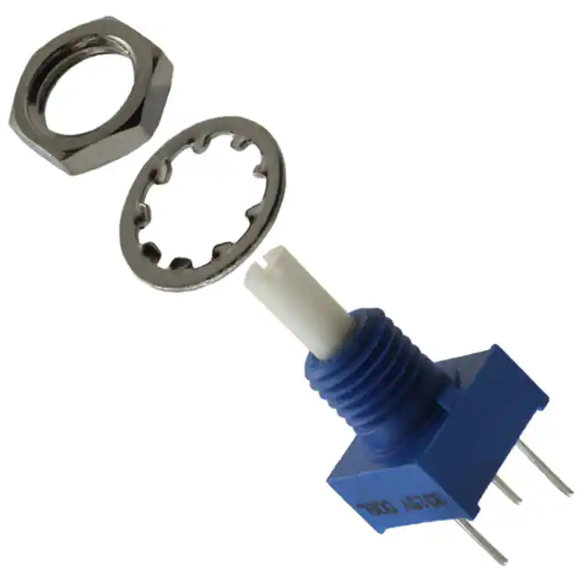


 工商网监
湘ICP备2023018690号
工商网监
湘ICP备2023018690号
