PL
IA
N
T
Features
M
■ Bushing mount
■ RoHS compliant*
*R
oH
S
CO
■ Optional center tap and rear shaft extension
■ Optional AR lug feature
■ Gangable with common or concentric shafts
■ High torque available
■ Non-standard features and specifications
available
3540/3541 - Precision Potentiometer
Electrical Characteristics1
3540 Wirewound Element
Product Dimensions
3541 Hybritron® Element
Standard Resistance Range................ 100 to 100 K ohms .....................1 K to 100 K ohms
Total Resistance Tolerance.................. ±5 % ...........................................±10 %
Independent Linearity .......................... ±0.25 % ......................................±0.25 %
Effective Electrical Angle ..................... 3600 ° +10 °, -0 ° .......................3600 ° +10 °, -0 °
Absolute Minimum Resistance/ ........... 1 ohm or 0.1 % maximum ..........0.2 % maximum
Minimum Voltage ............................. (whichever is greater)
Noise/Output Smoothness .................. 100 ohms ENR maximum ..........0.1 % maximum
Dielectric Withstanding Voltage (MIL-STD-202, Method 301)
Sea Level ......................................... 1,000 VAC minimum ..................1,000 VAC minimum
Power Rating (Voltage Limited By Power Dissipation or 447 VAC, Whichever Is Less)
+70 °C.............................................. 2 watts ........................................2 watts
+125 °C............................................ 0 watt..........................................0 watt
Insulation Resistance (500 VDC) ........ 1,000 megohms minimum ..........1,000 megohms minimum
Resolution............................................ See recommended part nos. .....Essentially infinite
3540S-1/3541H-1
18.3
(.72)
14.35 ± .38
(.565±.015)
5.72 ± .38
(.225±.015)
1
10.32 +.00/.05
DIA.
(.406+.000/-.002)
3
3/8 " 32-UNEF-2ATHD
.25
X 45 ° CHAMFER
(.010)
ADJUSTMENT
SLOT .81 WIDE
(.032)
X .81±.25 DEEP
(.032±.010)
2
Environmental Characteristics1
Operating Temperature Range ............ -40 °C to +125 °C .......................-40 °C to +125 °C
Storage Temperature Range ............... -55 °C to +125 °C .......................-55 °C to +125 °C
Temperature Coefficient Over
Storage Temperature Range2.......... ±50 ppm/°C maximum/unit .........±100 ppm/°C maximum/unit
Vibration .............................................. 15 G ...........................................15 G
Wiper Bounce .................................. 0.1 millisecond maximum ...........0.1 millisecond maximum
Shock................................................... 50 G ...........................................50 G
Wiper Bounce .................................. 0.1 millisecond maximum ...........0.1 millisecond maximum
Load Life .............................................. 1,000 hours, 2 watts ...................1,000 hours, 2 watts
Total Resistance Shift ...................... ±2 % ...........................................±5 %
Rotational Life (No Load)..................... 1,000,000 shaft revolutions2 .....5,000,000 shaft revolutions2
Total Resistance Shift ...................... ±5 % maximum ..........................±5 % maximum
Moisture Resistance (MIL-STD-202, Method 103, Condition B)
Total Resistance Shift ...................... ±2 % maximum ..........................±5 % maximum
IP Rating .............................................. IP 40 ...........................................IP 40
1.52
(.06)
6.342 + .000/ - .023
(.2497+.0000/-.0009)
DIA.
7.92 ± .38
(.312 ± .015)
19.05 ± .38
(.750 ± .015)
20.62 ± .79
(.812 ± .031)
OPTIONAL ANTIROTATION LUG
(-91) 1.42 X .50 ON 7.4 RADIUS.
LENGTH 1.27 FROM MOUNTING SURFACE.
(SUGGESTED PANEL HOLE 1.6 DIA.)
30 °
±5°
6.35
(.25)
Mechanical Characteristics1
Stop Strength.......................................................................................... 53 N-cm (75 oz-in.) minimum
Mechanical Angle ......................................................................................................3600 ° +10 °, -0 °
Torque
Starting & Running @ +25 °C ...............................................................0.49 N-cm (0.7 oz.-in.) max.
Starting & Running @ -40 °C................................................................1.76 N-cm (2.5 oz.-in.) max.
Mounting ..................................................................................... 170-200 N-cm (15-18 lb.-in.) max.
Shaft Runout.................................................................................................0.08 mm (0.003 in.) T.I.R.
Lateral Runout ..............................................................................................0.13 mm (0.005 in.) T.I.R.
Shaft End Play ..............................................................................................0.30 mm (0.012 in.) T.I.R.
Shaft Radial Play ..........................................................................................0.08 mm (0.003 in.) T.I.R.
Pilot Diameter Runout ..................................................................................0.08 mm (0.003 in.) T.I.R.
Backlash ....................................................................................................................... 1.0 ° maximum
Weight .................................................................................................................Approximately 21 gm
Terminals ......................................................................................................... Gold-plated solder lugs
Soldering Condition
Manual Soldering........................................................... 96.5Sn/3.0Ag/0.5Cu solid wire or no-clean
rosin cored wire; 370 °C (700 °F) max. for 3 seconds
Wave Soldering .................... 96.5Sn/3.0Ag/0.5Cu solder with no-clean flux; 260 °C (500 °F) max.
for 5 seconds
Wash processes ..................................................................................................Not recommended
Marking ................................................. Manufacturer’s name and part number, resistance value and
tolerance, linearity tolerance, wiring diagram, and date code
Ganging (Multiple Section Pots.) ............................................................................... 2 cups maximum
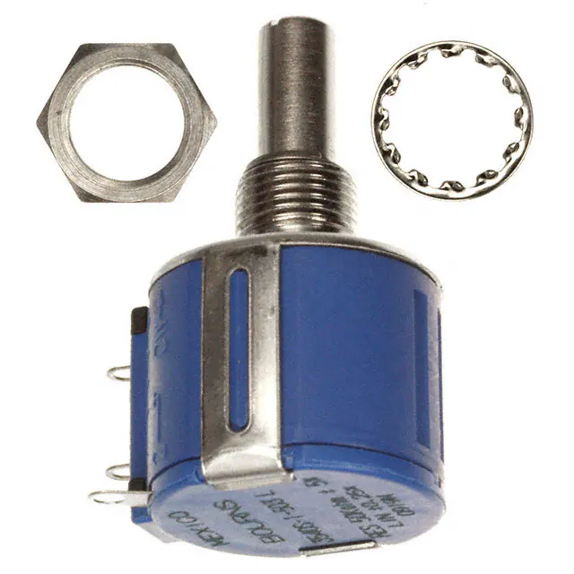
Hardware .................................................... One lockwasher (H-37-2) and one mounting nut (H-38-2)
is shipped with each potentiometer.
1At room ambient: +25 °C nominal and 50 % relative humidity nominal, except as noted.
2Consult manufacturer for complete specification details.
Recommended Part Numbers
Part Number
3540S-1-201L
3540S-1-501L
3540S-1-102L
3540S-1-202L
3540S-1-502L
3540S-1-103L
3540S-1-203L
3540S-1-503L
3540S-1-104L
Resistance (Ω)
200
500
1,000
2,000
5,000
10,000
20,000
50,000
100,000
Resolution
.042
.031
.027
.021
.021
.019
.014
.011
.008
*RoHS Directive 2015/863, Mar 31, 2015 and Annex.
Part Number
3541H-1-102L
3541H-1-202L
3541H-1-502L
3541H-1-103L
3541H-1-203L
3541H-1-503L
3541H-1-104L
Resistance (Ω)
1,000
2,000
5,000
10,000
20,000
50,000
100,000
15.88
R MAX.
(.625)
12.45
(.49)
22.23 ± .38
(.875 ± .015)
MTG. FACE
15.88
DIA. MIN.
(.625)
TOLERANCES: EXCEPT WHERE NOTED
.25
.13
DECIMALS: .XX ±
.XXX ±
(.010),
(.005)
FRACTIONS: ±1/64
MM
DIMENSIONS:
(IN.)
2
CCW
WIPER
3
1
CW
CLOCKWISE
BOLDFACE LISTINGS ARE IN STOCK AND READILY
AVAILABLE THROUGH DISTRIBUTION.
FOR OTHER OPTIONS CONSULT FACTORY.
ROHS IDENTIFIER:
L = COMPLIANT
WARNING
Cancer and Reproductive Harm
www.P65Warnings.ca.gov
Specifications are subject to change without notice. Users should verify actual device performance in their specific applications.
The products described herein and this document are subject to specific disclaimers as set forth on the last page
of this document, and at www.bourns.com/legal/disclaimer.pdf.
�3540/3541 - Precision Potentiometer
Panel Thickness Dimensions
2.46 - 3.81
(.097 - .150)
PANEL
HEX NUT
10.44 ± .07
DIA.
(.411 ± .003)
R
7.42
(.292)
ADDITIONAL HOLE FOR
ANTI-ROTATION PIN
1.60 +.08/-.03
DIA.
(.063 +.003/-.001)
LOCKWASHER
POT
Anti-rotation pin hole is shown at six o'clock
position for reference only. The actual location is
determined by the customer's application. Refer
to the front view of the potentiometer to see the
location of the optional A/R pin.
Panel thickness and hole diameters are
recommended for best fit. However, customers
may adjust the dimensions to suit their specific
application.
DIMENSIONS:
MM
(INCHES)
TOLERANCES: ±
0.127
(.005)
REV. 10/19
Specifications are subject to change without notice.
Users should verify actual device performance in their specific applications.
The products described herein and this document are subject to specific disclaimers as set forth on the last page of this document, and at www.bourns.com/legal/disclaimer.pdf.
�Legal Disclaimer Notice
This legal disclaimer applies to purchasers and users of Bourns® products manufactured by or on behalf of Bourns, Inc. and
P[Z�HɉSPH[LZ��JVSSLJ[P]LS`��¸)V\YUZ¹��
Unless otherwise expressly indicated in writing, Bourns® products and data sheets relating thereto are subject to change
^P[OV\[�UV[PJL���


 工商网监
湘ICP备2023018690号
工商网监
湘ICP备2023018690号
