T
PL
IA
N
M
CO
*R
oH
S
Features
■ Wirewound and Hybritron® elements
■ Designed for HMI and MMI applications
■ High rotational life
■ Dual gang option
■ Optional 0.15 % linearity
■ Servo mount option
■ Optional A/R lug
■ RoHS compliant*
■ Suitable for use under side load
3548 - 5-Turn Precision Potentiometer
Electrical Characteristics1
Wirewound Element
Hybritron® Element
Standard Resistance Range..................................................................500 to 50K ohms ....................................................1K to 10K ohms
Total Resistance Tolerance....................................................................±3 % .......................................................................±10 %
Independent Linearity ............................................................................±0.25 % ..................................................................±0.25 %
Independent Linearity (Maximum Practical) ..........................................±0.15 % ..................................................................±0.15 %
Effective Electrical Angle .......................................................................1800 ° +10 °, -0 °....................................................1800 ° +10 °, -0 °
Absolute Minimum Resistance/End Voltage ..........................................1 ohm or 0.1 % maximum ......................................0.4 % maximum
(whichever is greater)
Noise/Output Smoothness ....................................................................100 ohms maximum ...............................................0.15 % maximum
Max. Wiper Current @ 5K ohms ...........................................................20 mA .....................................................................10 mA
Dielectric Withstanding Voltage (MIL-STD-202, Method 301)
Sea Level ...........................................................................................1,000 VAC minimum ..............................................1,000 VAC minimum
Insulation Resistance (500 VDC) ..........................................................1,000 megohms minimum ......................................1,000 megohms minimum
Resolution..............................................................................................See How to Order chart ........................................Essentially infinite
Power Rating (Voltage Limited By Power Dissipation)
+70 °C................................................................................................1.5 watts .................................................................1.5 watts
+125 °C..............................................................................................0 watt......................................................................0 watt
Environmental Characteristics1
Operating Temperature Range
Dynamic .............................................................................................-40 °C to +125 °C ...................................................-40 °C to +125 °C
Static ..................................................................................................-55 °C to +125 °C ...................................................-55 °C to +125 °C
Temperature Coefficient (Over Static Temperature Range) ..................±50 ppm/°C ............................................................±100 ppm/°C
Temperature Cycling (5 Cycles Over Static Temperature Range) .........±2 % TR shift max. .................................................±4 % TR shift max.
Vibration (15 Gs, 10 Hz to 2 kHz)
Wiper Bounce ....................................................................................0.1 ms max.............................................................0.1 ms max.
Shock (100 Gs, 6 ms sawtooth)
Wiper Bounce ....................................................................................0.1 ms max.............................................................0.1 ms max.
Load Life (1,000 hours @ 70 °C)...........................................................±2 % TR shift max. .................................................±5 % TR shift max.
Rotational Life
No Load .............................................................................................1,000,000 shaft revolutions ...................................2,500,000 shaft revolutions
Powered (MIL-PRF-12934)................................................................1,000,000 shaft revolutions ...................................2,500,000 shaft revolutions
Moisture Resistance (Mil-Std-202, Method 103) ...................................±2 % TR shift max. .................................................±5 % TR shift max.
IP Rating ................................................................................................IP 50 .......................................................................IP 50
Mechanical Characteristics1
Mechanical Angle ...........................................................................................................................................................................................1800 ° +10 °, -0 °
Backlash .................................................................................................................................................................................................................... 1.0 ° max.
Stop Strength.......................................................................................................................................................................................53 N-cm (75 oz-in.) min.
Torque
Starting ........................................................................................................................................................................................0.5 N-cm (0.7 oz.-in.) max.
Running .......................................................................................................................................................................................0.5 N-cm (0.7 oz.-in.) max.
Clutch................................................................................................................................................................................1.0 to 4.2 N-cm (1.5 to 6.0 oz.-in.)
Mounting .......................................................................................................................................................................... 170-200 N-cm (15-18 in.-lb.) max.
Shaft Runout T.I.R. ..................................................................................................................................................................................... 0.08 mm (0.003 in.)
Lateral Runout T.I.R.................................................................................................................................................................................... 0.13 mm (0.005 in.)
Shaft End Play T.I.R. .................................................................................................................................................................................. 0.15 mm (0.006 in.)
Shaft Radial Play T.I.R................................................................................................................................................................................ 0.08 mm (0.003 in.)
Pilot Diameter Runout T.I.R. ....................................................................................................................................................................... 0.08 mm (0.003 in.)
Weight
Single .................................................................................................................................................................................................... 19 gm (0.67 oz.) typ.
Dual ..................................................................................................................................................................................................... 35 gm. (1.23 oz.) typ.
Shaft Side Load (Max. Allowable)
Nickel Plated Brass Shaft w/Brass Bushing ................................................................................................................................................. 50 gmf (1.7 ozf)
Stainless Steel Shaft w/Bronze Bushing .................................................................................................................................................... 250 gmf (8.8 ozf)
Terminals .............................................................................................................................................................................................. Gold-plated solder lugs
Soldering Condition
Manual Soldering ........................................................... 96.5Sn/3.0Ag/0.5Cu solid wire or no-clean rosin cored wire, 370 °C (700 °F) max. for 3 seconds
Wave Soldering ...................................................................................96.5Sn/3.0Ag/0.5Cu solder with no-clean flux, 260 °C (500 °F) max. for 5 seconds
Wash processes .......................................................................................................................................................................................Not recommended
Mounting Hardware ............................................................................................. One lockwasher and one mounting nut is shipped with each potentiometer
Recommended Panel Thickness (Bushing Mount) ..................................................................................................................2.46-3.81 mm (0.097-0.150 in.)
Marking ...........................................................................................................................Manufacturer’s symbol, model number, product code and date code
Standard Packaging ........................................................................................................................................................................... Plastic trays (5 pcs./tray)
1At room ambient: +25 °C nominal and 50 % relative humidity nominal, except as noted.
For other options, please consult factory.
WARNING
Cancer and Reproductive Harm
www.P65Warnings.ca.gov
*RoHS Directive 2015/863, Mar 31, 2015 and Annex.
Specifications are subject to change without notice. Users should verify actual device performance in their specific
applications. The products described herein and this document are subject to specific legal disclaimers as set forth on the
last page of this document, and at www.bourns.com/docs/legal/disclaimer.pdf.
�3548 - 5-Turn Precision Potentiometer
Product Dimensions
Single Gang, Bushing Mount
18.446 ± 0.381
(.726 ± .015)
2
1
Dual Gang, Bushing Mount
40.259 ± 0.762
(1.585 ± .030)
MOUNTING SURFACE
14.046 ± 0.381
(.553 ± .015)
5.715 ± 0.381
(.225 ± .015)
10.287 + 0.00/-0.05
(.405 +0.00/-.002)
3
39.243 ± 0.762
(1.545 ± .030)
34.798 ± 0.762
(1.370 ± .030)
26.467 ± 0.762
(1.042 ± .030)
18.796 ± 0.381
(.740 ± .015)
BUSHING TYPE “B”
R
14.351 ± 0.381
(.565 ± .015)
6.02 ± 0.381
(.237 ± .015)
0.762
(.030)
2
1
3
2
1
SHAFT
DIMENSION
“A”
10.287 + 0.00/-0.05
(.405 +0.00/-.002)
BUSHING TYPE “B”
3
ADJUSTMENT SLOT:
0.813
0.813
DEEP
WIDE X
(.032)
(.032)
SHAFT DIMENSION “A”
1.524 ± 0.254
(.060 ± .010)
7.92 ± 0.381
(.312 ± .015)
19.812 ± 0.812
(.780 ± .032)
20.617 ± 0.787
(.812 ± .031)
1.52
(.060)
7.92 ± 0.381
(.312 ± .015)
20.643 ± 0.787
(.813 ± .031)
0.813 ± .0004
0.813
WIDE X
ADJ. SLOT:
DEEP
(.032 ± .010)
(.032)
30 ° ± 5 °
OPTIONAL
ANTIROTATIONAL
PIN
6.86 ± 0.25
(.270 ± .010)
R 16.256
(.640)
MAX.
MOUNTING SURFACE
12.7 ± 0.254
(.500 ± .010)
1.524 +.000/-0.127
(.060 +.000/-.005)
DIA.
1.016
(.040)
OPTIONAL
ANTI-ROTATIONAL
PIN
22.479 ± 0.812
DIA.
(.885 ± .032)
2
CCW
30 ° ± 5 °
OPTIONAL
ANTIROTATIONAL
PIN
12.7 ± 0.254
(.500 ± .010)
DIA.
12.649 ± 0.254
(.498 ± .010)
MOUNTING FACE
WIPER
3
1
6.86 ± 0.25
(.270 ± .010)
R 16.256
(.640)
MAX.
CW
CLOCKWISE
TOLERANCES: EXCEPT WHERE NOTED
.50
.127
.0127
DECIMALS: .XX ± (.02) .XXX ± (.005) .XXXX ± (.0005)
MM
DIMENSIONS:
(IN)
Bushing
Selection
Bushing Material
Shaft Material
Bushing Type "B"
Shaft Dimension "A"
Code
6.34 +0/-0.022
Brass
Nickel Plated Brass 3/8 " 32-UNEF- 2A THD.
A
(0.2497 +0/-0.0009)
6.00 +0/-0.022
Brass
Nickel Plated Brass
M9 X 0.75-8g
B
(0.2362 +0/-0.0009)
6.34 +0/-0.007
Bronze
Stainless Steel
3/8 " 32-UNEF- 2A THD.
C
(0.2497 +0/-0.0003)
6.00 +0/-0.007
Bronze
Stainless Steel
M9 X 0.75-8g
D
(0.2362 +0/-0.0003)
6.34 +0/-0.007
Bronze
Stainless Steel
3/8 " 32-UNEF- 2A THD.
G
(0.2497 +0/-0.0003)
6.00 +0/-0.007
Bronze
Stainless Steel
M9 X 0.75-8g
H
(0.2362 +0/-0.0003)
1.524 +.000/-0.127
(.060 +.000/-.005)
DIA.
1.016
(.040)
OPTIONAL
ANTI-ROTATIONAL
PIN
CCW
3
1
2
CCW
22.479 ± 0.812
DIA.
(.885 ± .032)
2
CW
WIPER
3
1
DIA.
12.649 ± 0.254
(.498 ± .010)
MOUNTING FACE
CW
CLOCKWISE
Specifications are subject to change without notice.
Users should verify actual device performance in their specific applications.
The products described herein and this document are subject to specific legal
disclaimers as set forth on the last page of this document, and at
www.bourns.com/docs/legal/disclaimer.pdf.
�3548 - 5-Turn Precision Potentiometer
Product Dimensions
Single Gang, Servo Mount
Dual Gang, Servo Mount
23.86 ± 0.381
(.939 ± .015)
19.46 ± 0.381
(.766 ± .015)
2
1
45.67 ± 0.78
(1.798 ± .031)
44.65 ± 0.78
(1.758 ± .031)
40.21 ± 0.78
(1.583 ± .031)
31.88 ± 0.78
(1.255 ± .031)
24.206 ± 0.381
(.953 ± .015)
19.76 ± 0.381
(.778 ± .015)
MOUNTING SURFACE
11.13 ± 0.381
(.438 ± .015)
15.8725 + .0000/-.0127
DIA.
(.6249 +.0000/-.0005)
3
17.526
DIA.
(.690)
DIA.
3.1699 + .0000/-.0076
(.1248 + .0000/-.0003)
2
1
3
2
1
MOUNTING SURFACE
11.43 ± 0.381
(.450 ± .015)
15.8725 + .0000/-.0127
DIA.
(.6249 +.0000/-.0005)
3
17.526
DIA.
(.690)
DIA.
3.1699 + .0000/-.0076
(.1248 + .0000/-.0003)
1.575
(.062)
1.575
(.062)
1.575
(.062)
9.525 ± 0.787
(.375 ± .031)
25.222 ± 0.787
(.993 ± .031)
1.575
(.062)
1.575
(.062)
1.575
(.062)
30 ° ± 5 °
6.858 ± 0.254
(.270 ± .010)
R 16.256
(.640)
MAX.
30 ° ± 5 °
6.858 ± 0.254
(.270 ± .010)
12.7 ± 0.254
(.500 ± .010)
R 16.256
(.640)
MAX.
12.7 ± 0.254
(.500 ± .010)
22.225 ± 0.381
(.875 ± .015)
DIA.
2
CCW
WIPER
3
1
22.225 ± 0.381
(.875 ± .015)
DIA.
CW
CLOCKWISE
TOLERANCES: EXCEPT WHERE NOTED
.50
.127
.0127
DECIMALS: .XX ± (.02) .XXX ± (.005) .XXXX ± (.0005)
MM
DIMENSIONS:
(IN)
CCW
2
CCW
Specifications are subject to change without notice.
Users should verify actual device performance in their specific applications.
The products described herein and this document are subject to specific legal
disclaimers as set forth on the last page of this document, and at
www.bourns.com/docs/legal/disclaimer.pdf.
3
1
2
WIPER
3
1
CLOCKWISE
CW
CW
9.525 ± 0.787
(.375 ± .031)
�3548 - 5-Turn Precision Potentiometer
Panel Thickness Dimensions
How To Order
(For Bushing Mount Only)
3
2.46 - 3.81
(.097 - .150)
5 4 8 S
-
2 A A -
1
0 3
/
1
0 3 A
PANEL
MODEL DESIGNATOR
Code Description
3548 5-Turn
HEX NUT
INDEPENDENT LINEARITY
Code Description
A
0.25 %
B
0.15 %
ELEMENT TYPE
Code Description
H
Hybritron®
S
Wirewound
RESISTANCE**
Code
Element Type Resolution (%)
102 (1K ohms)
—
Hybritron®
502 (5K ohms)
—
Hybritron®
103 (10K ohms) Hybritron®
—
201 (200 ohms) Wirewound
0.069
501 (500 ohms) Wirewound
0.054
102 (1K ohms)
0.043
Wirewound
202 (2K ohms)
0.044
Wirewound
502 (5K ohms)
0.038
Wirewound
103 (10K ohms) Wirewound
0.029
203 (20K ohms) Wirewound
0.023
503 (50K ohms) Wirewound
0.017
NO. OF SECTIONS
Code Description
1
Single
2
Dual
LOCKWASHER
POT
ANTI-ROTATION LUG
Code Description
A
None
B
180 °
10.44 ± .07
DIA.
(.411 ± .003)
* Anti-rotation lug is not available for
servo mount versions.
R
7.42
(.292)
** For Single gang, use only first three digits.
For Dual gang, use six digits separated by a "/".
BUSHING MOUNT
ADDITIONAL HOLE FOR
ANTI-ROTATION PIN
1.60 +.08/-.03
DIA.
(.063 +.003/-.001)
Anti-rotation pin hole is shown at six o'clock
position for reference only. The actual location is
determined by the customer's application. Refer
to the front view of the potentiometer to see the
location of the optional A/R pin.
Code
A
B
C
D
G
H
Shaft FMS
13/16 ˝
20.6 mm
13/16 ˝
20.6 mm
13/16 ˝
20.6 mm
Code
E
Shaft FMS
3/8 ˝
Shaft Dia.
1/4 ˝
6 mm
1/4 ˝
6 mm
1/4 ˝
6 mm
Shaft Material
Nickel Plated Brass
Nickel Plated Brass
Stainless Steel
Stainless Steel
Stainless Steel
Stainless Steel
SERVO MOUNT
Shaft Dia.
1/8 ˝
Shaft Material
Stainless Steel
Bushing Dia.
3/8 ˝
9 mm
3/8 ˝
9 mm
3/8 ˝
9 mm
Bushing Material
Brass
Brass
Bronze
Bronze
Bronze
Bronze
Slip Clutch
N/A
N/A
N/A
N/A
Yes***
Yes***
*** Not available in dual gang version.
Panel thickness and hole diameters are
recommended for best fit. However, customers
may adjust the dimensions to suit their specific
application.
DIMENSIONS:
MM
(INCHES)
TOLERANCES: ±
0.127
(.005)
Asia-Pacific: Tel: +886-2 2562-4117 • Email: asiacus@bourns.com
EMEA: Tel: +36 88 885 877 • Email: eurocus@bourns.com
The Americas: Tel: +1-951 781-5500 • Email: americus@bourns.com
www.bourns.com
REV. 10/19
“Hybritron” is a registered trademark of Bourns, Inc.
Specifications are subject to change without notice.
Users should verify actual device performance in their specific applications.
The products described herein and this document are subject to specific legal disclaimers as set forth on the last page of this document, and at www.bourns.com/docs/legal/disclaimer.pdf.
�Legal Disclaimer Notice
This legal disclaimer applies to purchasers and users of Bourns® products manufactured by or on behalf of Bourns, Inc. and
P[Z�HɉSPH[LZ��JVSSLJ[P]LS`��¸)V\YUZ¹��
Unless otherwise expressly indicated in writing, Bourns® products and data sheets relating thereto are subject to change
^P[OV\[�UV[PJL���
很抱歉,暂时无法提供与“3548S-2AA-502/502B”相匹配的价格&库存,您可以联系我们找货
免费人工找货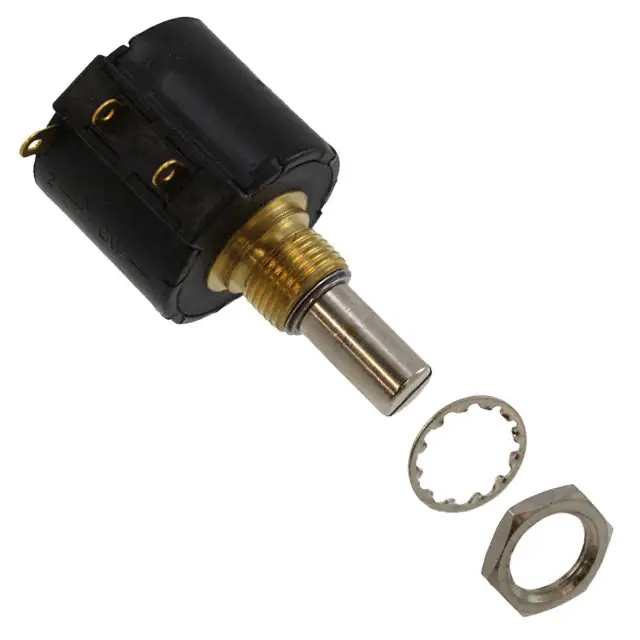


 工商网监
湘ICP备2023018690号
工商网监
湘ICP备2023018690号
