PL
IA
N
T
Features
M
■ Infinite resolution element
*R
oH
S
CO
■ Standard linearity: 1.0 %
■ Non-standard features and specifications
available
■ Extended temperature range:
-65 °C to +125 °C
■ Extended life version (6538)
■ Output smoothness: 0.1 % standard
■ Molded-in rear terminals
6537/6538 - 22 mm Precision Potentiometer
Electrical Characteristics1
6 5 37
Product Dimensions
6 53 8
Standard Resistance Range................ 1 K to 100 K ohms......................1 K to 100 K ohms
Total Resistance Tolerance.................. ±10 % .........................................±10 %
Independent Linearity .......................... ±1 % ...........................................±1 %
Effective Electrical Angle ..................... 340 ° ±3 ° ...................................340 ° ±3 °
End Voltage ......................................... 0.5 % maximum .........................0.5 % maximum
Output Smoothness ............................. 0.1 % ..........................................0.1 %
Dielectric Withstanding Voltage (MIL-STD-202, Method 301)
Sea Level ......................................... 750 VAC minimum .....................750 VAC minimum
Power Rating (Voltage Limited By Power Dissipation or 300 VAC, Whichever is Less)
+70 °C.............................................. 1 watt..........................................1 watt
+125 °C............................................ 0 watt..........................................0 watt
Insulation Resistance (500 VDC) ........ 1,000 megohms minimum ..........1,000 megohms minimum
Resolution............................................ Essentially infinite.......................Essentially infinite
6537
12.70 ± .38
(.500 ± .015)
1.57
(.062)
3.170+.000/-.008 DIA.
(.1248+.0000/-.0003)
.25
45 ± 5 ° x
CHAMFER
(.010)
1.57
(.062)
1.57
(.062)
22.23
(.875)
DIA.
.51
REF.
(.020)
Environmental Characteristics1
Operating Temperature Range ............ -40 °C to +125 °C .......................-40 °C to +125 °C
Storage Temperature Range ............... -65 °C to +125 °C .......................-65 °C to +125 °C
Temperature Coefficient
Over Storage Temperature Range ...... ±500 ppm/°C maximum..............±500 ppm/°C maximum
Vibration .............................................. 15 G ...........................................15 G
Wiper Bounce .................................. 0.1 millisecond maximum ...........0.1 millisecond maximum
Total Resistance Shift ...................... ±5 % maximum ..........................±5 % maximum
Voltage Ratio Shift ........................... ±0.5 % maximum .......................±0.5 % maximum
Shock................................................... 50 G ...........................................50 G
Wiper Bounce .................................. 0.1 millisecond maximum ...........0.1 millisecond maximum
Total Resistance Shift ...................... ±5 % maximum ..........................±5 % maximum
Voltage Ratio Shift ........................... ±0.5 % maximum .......................±0.5 % maximum
Load Life .............................................. 1,000 hours, 1 watt.....................1,000 hours, 1 watt
Total Resistance Shift ...................... ±10 % maximum ........................±10 % maximum
Rotational Life (No Load)..................... 10,000,000 shaft revolutions ......20,000,000 shaft revolutions
Total Resistance Shift ...................... ±10 % maximum ........................±10 % maximum
Moisture Resistance (MIL-STD-202, Method 106)
Total Resistance Shift ...................... ±15 % maximum ........................±10 % maximum
IP Rating .............................................. IP 40 ...........................................IP 50
19.050+.000/-.012
(.75+.0000/-.0005)
DIA.
3.18
(.125)
12.70 ± .80 19.81
(.375 ± .031) (.780)
DIA.
4.80
R
(.19)
30 ± 3 °
TYP.
6538 BALL BEARING
12.70 ± .38
(.475 ± .015)
1.57
(.062)
1.57
(.062)
1.57
(.062)
Mechanical Characteristics1
Mechanical Angle ................................ Continuous ................................Continuous
Torque (Starting & Running) ..................0.40 N-cm (0.5 oz.-in.) max. ...... 0.18 N-cm (0.25 oz.-in.) max.
Shaft Runout........................................ 0.025 mm (0.001 in.) T.I.R. ........0.025 mm (0.001 in.) T.I.R.
Lateral Runout ..................................... 0.08 mm (0.003 in.) T.I.R. ..........0.08 mm (0.003 in.) T.I.R.
Shaft End Play ..................................... 0.13 mm (0.005 in.) T.I.R. ..........0.13 mm (0.005 in.) T.I.R.
Shaft Radial Play ................................. 0.13 mm (0.005 in.) T.I.R. ..........0.08 mm (0.003 in.) T.I.R.
Pilot Diameter Runout ......................... 0.06 mm (0.0025 in.) T.I.R. ........0.06 mm (0.0025 in.) T.I.R.
Backlash .............................................. 0.1 ° maximum...........................0.1 ° maximum
Weight ................................................. 18 gm.........................................18 gm
Terminals ...................................................................................................... Molded-in rear turret type
Soldering Condition
Manual Soldering .................................96.5Sn/3.0Ag/0.5Cu solid wire or no-clean rosin cored wire
370 °C (700 °F) max. for 3 seconds
Wave Soldering ........................................................ 96.5Sn/3.0Ag/0.5Cu solder with no-clean flux
260 °C (500 °F) max. for 5 seconds
Wash processes ..................................................................................................Not recommended
Marking ................................................. Manufacturer’s name and part number, resistance value and
tolerance, linearity tolerance, wiring diagram, and date code.
Ganging (Multiple Section Pots.) ................................................................................. 1 cup maximum
Hardware ........................................................................................................... No hardware included
.25
45 ± 15 ° x
(.010)
CHAMFER
22.23 ± 0.38
(.875 ± .015)
DIA.
.51
REF.
(.020)
19.050+.000/-.012
(.75+.0000/-.0005)
DIA.
3.18 ± 0.38
(.125 ± .015)
12.70 ± .38
(.500 ± .031)
19.81
(.780)
DIA.
5.08
R
(.020)
45 ± 5 °
1At room ambient: +25 °C nominal and 50 % relative humidity nominal, except as noted.
TOLERANCES: EXCEPT WHERE NOTED
±.25
±.13
DECIMALS: .XX
.XXX
±(.020),
±(.005)
FRACTIONS: 1/64
MM
DIMENSIONS:
(IN.)
Recommended Part Numbers
Part Number
6537S- 1- 102
6537S- 1- 502
6537S-1-103
Resistance (Ω)
1,000
5,000
10,000
Part Number
6538S- 1- 102
6538S- 1- 202
6538S- 1- 502
6538S-1-103
BOLDFACE LISTINGS ARE IN STOCK AND READILY AVAILABLE THROUGH DISTRIBUTION.
FOR OTHER OPTIONS CONSULT FACTORY.
WARNING
Cancer and Reproductive Harm
www.P65Warnings.ca.gov
Resistance (Ω)
1,000
2,000
5,000
10,000
2
CCW
WIPER
3
1
CW
CLOCKWISE
*RoHS Directive 2015/863, Mar 31, 2015 and Annex.
REV. 10/19
Specifications are subject to change without notice. Users should verify actual device performance in their specific
applications. The products described herein and this document are subject to specific legal disclaimers as set forth on the
last page of this document, and at www.bourns.com/docs/legal/disclaimer.pdf.
�Legal Disclaimer Notice
This legal disclaimer applies to purchasers and users of Bourns® products manufactured by or on behalf of Bourns, Inc. and
P[Z�HɉSPH[LZ��JVSSLJ[P]LS`��¸)V\YUZ¹��
Unless otherwise expressly indicated in writing, Bourns® products and data sheets relating thereto are subject to change
^P[OV\[�UV[PJL���
很抱歉,暂时无法提供与“6538S-1-503”相匹配的价格&库存,您可以联系我们找货
免费人工找货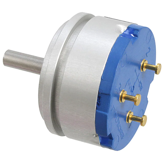


 工商网监
湘ICP备2023018690号
工商网监
湘ICP备2023018690号
