T
PL
IA
N
M
CO
*R
oH
S
Features
■ Absolute encoder / absolute code output
■ Digital output
■ Sturdy construction
■ Bushing mount
■ Available with PC board mounting bracket (optional)
■ *RoHS compliant
EAW - Absolute Contacting Encoder (ACE™)
General Information
Until now, the choice of an absolute
encoder meant an expensive, and largersized product. Through the use of
combinatorial mathematics, the absolute
code pattern of the Bourns® Absolute
Contacting Encoder (ACE™) is placed on a
single track for a very economical, energyefficient and compact product. Bourns®
ACE™ provides an absolute digital output
that will also retain its last position in the
event of a power failure.
An intelligent alternative to incremental
encoders and potentiometers, the Bourns®
ACE™ is ideally suited for many industrial,
medical and consumer product applications.
Recommended Control Diagram for ACE-128
“common” is either
on a decoded
“select” pin
(active low)
or at GND.
1
2
C
3
4
8
7
C
6
5
P 1 P2 P3 P4 P5 P6 P7 P8
P
RESNET
4609X101-472
ACETAB:
256 byte
code
conversion
table (ROM)
Electrical Characteristics
Output ...............................................................................................................................................................................8-bit code with 128 absolute states
Closed Circuit Resistance ...........................................................................................................................................................................5 ohms maximum
Open Circuit Resistance ....................................................................................................................................................................... 100 K ohms minimum
Contact Rating .................................................................................................................................................. 10 milliamp @ 10 VDC or 0.1 watt maximum
Insulation Resistance (500 VDC) ...................................................................................................................................................1,000 megohms minimum
Dielectric Withstanding Voltage (MIL-STD-202 Method 301)
Sea Level ............................................................................................................................................................................................ 1,000 VAC minimum
Electrical Travel .....................................................................................................................................................................................................Continuous
Contact Bounce (60 RPM)........................................................................................................................................................... 2.7 milliseconds maximum*
RPM (Operating) .............................................................................................................................................................................................. 120 maximum
Environmental Characteristics
Operating Temperature Range .......................................................................................................................................-40 ºC to +85 ºC (-40 °F to +185 °F)
Storage Temperature Range ..........................................................................................................................................-40 ºC to +85 ºC (-40 °F to +185 °F)
Humidity................................................................................................................................................................. MIL-STD-202, Method 103B, Condition B
Vibration .......................................................................................................................................................................................................................... 15 G
Contact Bounce ...........................................................................................................................................................................0.1 millisecond maximum
Shock............................................................................................................................................................................................................................... 50 G
Contact Bounce ...........................................................................................................................................................................0.1 millisecond maximum
Rotational Life.................................................................................................................................................................... 50,000 shaft revolutions minimum
IP Rating ..........................................................................................................................................................................................................................IP 40
Mechanical Characteristics
Mechanical Angle ........................................................................................................................................................................................ 360 ° Continuous
Running Torque .............................................................................................................................................................. 0.5 to 1.5 N-cm (0.75 to 2.50 oz-in.)
Mounting Torque .........................................................................................................................................................................79 N-cm (7 lb.-in.) maximum
Shaft Side Load (Static)....................................................................................................................................................................4.5 kg (10 lbs.) minimum
Weight ................................................................................................................................................................................ Approximately 14 gms. (0.50 oz.)
Terminals ................................................................................................................................................................................. Printed circuit board terminals
Soldering Condition
Manual Soldering ................................................................................................................... 96.5Sn/3.0Ag/0.5Cu solid wire or no-clean rosin cored wire
370 °C (700 °F) max. for 3 seconds
Wave Soldering ...........................................................................................................................................96.5Sn/3.0Ag/0.5Cu solder with no-clean ux
260 °C (500 °F) max. for 5 seconds
Wash processes .................................................................................................................................................................................... Not recommended
Marking ...........................................................................................................................Manufacturer’s name and trademark, part number, and date code.
Hardware ................................................. One lockwasher and one mounting nut are shipped with each encoder, except where noted in the part number.
Packaging ............................................................................................................................................................................................................. 45 pcs./tray
*High probability of missing quadrature codes with maximum bounce.
WARNING Cancer and Reproductive Harm
www.P65Warnings.ca.gov
*RoHS Directive 2015/863, Mar 31, 2015 and Annex.
Specifications are subject to change without notice. Users should verify actual device performance in their specific
applications. The products described herein and this document are subject to specific legal disclaimers as set forth on the
last page of this document, and at www.bourns.com/docs/legal/disclaimer.pdf.
�EAW - Absolute Contacting Encoder (ACE™)
Pin Output Code For ACE-128
Bit/Pin correlation: b7 b6 b5 b4 b3 b2 b1 b0 = p8 p7 p6 p5 p4 p3 p2 p1
A binary “1” denotes an “open” switch and a binary “0” denotes a “closed” switch.
Positions 0-127 are seen by a clockwise rotation of the shaft.
Position
p8
p7
p6
p5
p4
p3
p2
p1
Decimal
Output
0
1
2
3
4
5
6
7
8
9
10
11
12
13
14
15
16
17
18
19
20
21
22
23
24
25
26
27
28
29
30
31
32
33
34
35
36
37
38
39
40
41
42
43
44
45
46
47
48
49
50
51
52
53
54
55
56
57
58
59
60
61
62
63
0
0
0
0
0
1
1
0
0
0
0
0
0
0
0
1
1
1
0
0
0
0
0
0
0
0
1
1
1
1
1
1
1
1
1
1
0
0
0
0
0
0
0
0
1
1
1
1
1
1
1
0
0
0
0
0
0
0
0
1
1
1
1
1
1
0
0
0
0
0
0
0
0
1
1
1
1
0
0
0
0
0
0
0
0
1
1
0
0
0
0
0
0
0
0
1
1
1
0
0
0
0
0
0
0
0
1
1
1
1
1
1
1
1
1
1
0
0
0
0
0
0
0
0
1
1
1
1
1
1
1
1
1
1
0
0
0
0
0
0
0
0
1
1
1
0
0
0
0
0
0
0
0
1
1
1
1
0
0
0
0
0
0
0
0
1
1
0
0
0
0
0
0
0
0
1
1
1
0
0
0
0
0
0
0
0
1
1
1
1
1
1
1
1
1
1
1
1
1
1
0
0
0
0
0
0
0
0
1
1
1
1
1
1
0
0
0
0
0
0
0
0
1
1
1
0
0
0
0
0
0
0
0
1
1
1
1
0
0
0
0
0
0
0
0
1
1
0
0
0
0
0
0
0
0
1
1
1
1
1
1
1
1
1
1
1
1
1
1
1
1
1
1
1
1
1
1
1
1
1
0
0
0
0
0
0
0
0
1
1
1
1
1
1
0
0
0
0
0
0
0
0
1
1
1
0
0
0
0
0
0
0
0
1
1
1
1
0
0
0
1
1
1
0
0
0
0
0
0
0
0
1
1
1
1
1
1
1
1
1
1
1
1
1
1
1
1
1
1
1
1
1
1
1
1
1
1
1
1
1
0
0
0
0
0
0
0
0
1
1
1
1
1
1
0
0
0
0
0
0
0
0
1
1
1
1
1
1
0
0
0
0
0
0
0
0
1
1
1
1
1
1
1
0
0
0
0
0
0
0
0
1
1
1
1
1
1
1
1
1
1
1
1
1
1
1
1
1
1
1
1
1
1
1
1
1
1
1
1
1
0
0
0
0
0
0
0
0
1
1
0
0
0
0
0
0
0
0
1
1
1
1
1
1
1
1
1
1
0
0
0
0
0
0
0
0
1
1
1
1
1
1
1
0
0
0
0
0
0
0
0
1
1
1
1
1
1
1
1
1
1
1
1
1
1
1
1
1
1
1
1
1
127
63
62
58
56
184
152
24
8
72
73
77
79
15
47
175
191
159
31
29
28
92
76
12
4
36
164
166
167
135
151
215
223
207
143
142
14
46
38
6
2
18
82
83
211
195
203
235
239
231
199
71
7
23
19
3
1
9
41
169
233
225
229
245
Position
64
65
66
67
68
69
70
71
72
73
74
75
76
77
78
79
80
81
82
83
84
85
86
87
88
89
90
91
92
93
94
95
96
97
98
99
100
101
102
103
104
105
106
107
108
109
110
111
112
113
114
115
116
117
118
119
120
121
122
123
124
125
126
127
p8
p7
p6
p5
p4
p3
p2
1
1
1
1
1
1
1
1
1
1
1
1
1
1
1
1
1
1
1
1
1
1
1
1
0
0
0
0
0
0
0
0
1
1
1
1
1
1
0
0
0
0
0
0
0
0
1
1
1
0
0
0
0
0
0
0
0
1
1
1
1
0
0
0
1
1
1
0
0
0
0
0
0
0
0
1
1
1
1
1
1
1
1
1
1
1
1
1
1
1
1
1
1
1
1
1
1
1
1
1
1
1
1
1
0
0
0
0
0
0
0
0
1
1
1
1
1
1
0
0
0
0
0
0
0
0
1
1
1
1
1
1
0
0
0
0
0
0
0
0
1
1
1
1
1
1
1
0
0
0
0
0
0
0
0
1
1
1
1
1
1
1
1
1
1
1
1
1
1
1
1
1
1
1
1
1
1
1
1
1
1
1
1
1
0
0
0
0
0
0
0
0
1
1
0
0
0
0
0
0
0
0
1
1
1
1
1
1
1
1
1
1
0
0
0
0
0
0
0
0
1
1
1
1
1
1
1
0
0
0
0
0
0
0
0
1
1
1
1
1
1
1
1
1
1
1
1
1
1
1
1
1
1
1
1
1
0
0
0
0
0
1
1
0
0
0
0
0
0
0
0
1
1
1
0
0
0
0
0
0
0
0
1
1
1
1
1
1
1
1
1
1
0
0
0
0
0
0
0
0
1
1
1
1
1
1
1
0
0
0
0
0
0
0
0
1
1
1
1
1
1
0
0
0
0
0
0
0
0
1
1
1
1
0
0
0
0
0
0
0
0
1
1
0
0
0
0
0
0
0
0
1
1
1
0
0
0
0
0
0
0
0
1
1
1
1
1
1
1
1
1
1
0
0
0
0
0
0
0
0
1
1
1
1
1
1
1
1
1
1
0
0
0
0
0
0
0
0
1
1
1
0
0
0
0
0
0
0
0
1
1
1
1
0
0
0
0
0
0
0
0
1
1
0
0
0
0
0
0
0
0
1
1
1
0
0
0
0
0
0
0
0
1
1
1
1
1
1
p1
1
1
1
1
1
1
1
1
0
0
0
0
0
0
0
0
1
1
1
1
1
1
0
0
0
0
0
0
0
0
1
1
1
0
0
0
0
0
0
0
0
1
1
1
1
0
0
0
0
0
0
0
0
1
1
0
0
0
0
0
0
0
0
1
Decimal
Output
247
243
227
163
131
139
137
129
128
132
148
212
244
240
242
250
251
249
241
209
193
197
196
192
64
66
74
106
122
120
121
125
253
252
248
232
224
226
98
96
32
33
37
53
61
60
188
190
254
126
124
116
112
113
49
48
16
144
146
154
158
30
94
95
Specifications are subject to change without notice.
Users should verify actual device performance in their specific applications.
The products described herein and this document are subject to specific legal disclaimers as set forth on the last page of this document, and at www.bourns.com/docs/legal/disclaimer.pdf.
�EAW - Absolute Contacting Encoder (ACE™)
Dimensional Drawings
Bushing Mounted: Housing A with Rear Facing Terminals
23.88
(.940)
6.32 +0.03/-0.08
(.249 +.001/-.003)
22.2 ± .25
(.874 ± .010)
9.02 ± .15
(.355 ± .006)
1.19
(.047)
8
7
C
6
5
12.7
(.500)
14.7 ± 0.5
(.578 ± .020)
DIA.
8.51 ± .25
(.335 ± .010)
19.05 ± .38
(.750 ± .015)
6.35
(.250)
1.6
(.063)
11.1
(.437)
1.52
(.060)
27.94 ± .25
(1.100 ± .010)
2.79
(.110)
13.97
(.550)
1
2
C
3
1.19
(.047)
M9 X 0.75-6g SPL
9.0
DIA.
(.354)
4
0.64 ± 0.03
(.025 ± .001)
10 PLCS.
3.68 ± .38
(.145 ± .015)
2.54
(.100)
8 PLCS.
Bushing Mounted: Housing A with Forward Facing Terminals
23.88
(.940)
22.2 ± .25
(.874 ± .010)
9.02 ± .15
(.355 ± .006)
1.19
(.047)
8
7
C
6
5
12.7
(.500)
14.7 ± 0.5
DIA.
(.578 ± .020)
11.1
(.437)
19.05 ± .38
(.750 ± .015)
6.35
(.250)
8.51 ± .25
(.335 ± .010)
1.6
(.063)
1.52
(.060)
27.94 ± .25
(1.100 ± .010)
2.79
(.110)
13.97
(.550)
1
2
C
3
6.32 +0.03/-0.08
(.249 +.001/-.003)
1.19
(.047)
M9 X 0.75-6g SPL
9.0
DIA.
(.354)
4
0.64 ± 0.03
(.025 ± .001)
10 PLCS.
2.54 ± .25
(.100 ± .010)
2.54
(.100)
8 PLCS.
PCB Bracket Mounted: Housing B
23.88
(.940)
22.2 ± .25
(.874 ± .010)
1.19
(.047)
6.32 +0.03/-0.08
(.249 +.001/-.003)
9.02 ± .15
(.355 ± .006)
8
7
C
6
5
12.7
(.500)
11.1
(.437)
17.07 ± .25
(.672 ± .010)
2.79
(.110)
1.6
(.063)
1.02
(.040)
27.94 ± .25
(1.100 ± .010)
13.97
(.550)
1
2
C
3
4
23.37 ± .25
(.920 ± .010)
18.54 ± .38
(.730 ± .015)
1.19
(.047)
M9 X 0.75-6g SPL
9.0
DIA.
(.354)
9.02
(.355)
0.76
TYP. 4 PLCS.
(.030)
5.08
(.200)
0.64 ± 0.03
(.025 ± .001)
10 PLCS.
2.54
(.100)
0.51
(.020)
Specifications are subject to change without notice.
Users should verify actual device performance in their specific applications.
The products described herein and this document are subject to specific legal disclaimers as set forth on the last page of this document, and at www.bourns.com/docs/legal/disclaimer.pdf.
�EAW - Absolute Contacting Encoder (ACE™)
Dimensional Drawings
Shaft Style B
1.6
(.063)
Shaft Style R
Shaft Style C
6.32 + 0.03/– 0.06
DIA.
(.249 + .001/– .003)
6.00 ± 0.05
DIA.
(.236 ± .002)
5.54 ± .076
(.218 ± .003)
1.19
(.047)
"D"
6.32 + 0.03/– 0.06
DIA.
(.249 + .001/– .003)
1.6
(.063)
1.19
(.047)
"D" DIMENSION EXTENDS FROM SHAFT END TO BUSHING FACE
"D" = (SHAFT LENGTH, FMS) – (BUSHING LENGTH)
Bushing Mounted: Housing A with Forward Facing Terminals
Bushing Mounted: Housing A with Rear Facing Terminals
Panel Hole Dimensions
PCB Board Hole Pattern w/PCB Bracket
PCB Board Hole Pattern w/PCB Bracket
2.54
TYP.
(.100)
2.54
TYP.
(.100)
9.5
(.375)
9.5
(.375)
9.93
DIA.
(.391)
25.4
(1.00)
3.17
DIA.
(.125)
9.93
DIA.
(.391)
25.4
(1.00)
3.17
DIA.
(.125)
1.2
DIA. 10 PLCS.
(.047)
1.2
DIA. 10 PLCS.
(.047)
PCB Bracket Mounted: Housing B
Panel Hole Dimensions
PCB Board Hole Pattern w/PCB Bracket
5.08
2 PLCS.
(.200)
9.5
(.375)
3.17
DIA.
(.125)
2.54
TYP.
(.100)
9.93
DIA.
(.391)
15.24
(.600)
25.4
(1.00)
TOLERANCES EXCEPT WHERE NOTED:
.127
.51
.XX = ±
.XXX = ±
(.005)
(.02)
DIMENSIONS:
MM
(IN)
1.2
DIA. 14 PLCS.
(.047)
11.43
2 PLCS.
(.450)
Specifications are subject to change without notice.
Users should verify actual device performance in their specific applications.
The products described herein and this document are subject to specific legal disclaimers as set forth on the last page of this document, and at www.bourns.com/docs/legal/disclaimer.pdf.
�EAW - Absolute Contacting Encoder (ACE™)
How to Order
PART NUMBERING SYSTEM
E A W 0 J
-
B 2 4
- A E 0 1 2 8
Code Rotational Life
A
50,000 Revolutions
BUSHING CONFIGURATION
Code Description
W
9 mm x 1/4 ˝ Length. Threaded M9x0.75
L
9 mm x 3/8 ˝ Length. Threaded M9x0.75
(Use B shaft only.)
DETENT CONFIGURATION
Code Description
0
Non-Detented
ANTI-ROTATION LUG POSITION
Code Description
J
9:00 Position
D
None
L
RoHS IDENTIFIER
Code Description
L
Compliant
PERFORMANCE CODE
Code Detents States/Rev.
E0128
0
128
HOUSING TERMINAL CONFIGURATION
(X indicates “Equipped With”)
Code
Features
A
B
C
H
Rear Mount Terminals
X
X
X
Forward Facing Terminals
X
PCB Bracket
X
X
Hardware Included
X
X
X
K
X
SHAFT LENGTH (FMS)
Available
Code Description
Shaft Styles
24
3/4 ˝ (19.05 mm) Length
B, C
Metric
19
19 mm Length
R
SHAFT STYLE (See Outline Drawing for Details)
Code Description
B
Plain with Inserted Slot (1/4 ˝ Dia.)
C
Single Flatted (1/4 ˝ Dia.)
R
Plain with Inserted Slot (6 mm Dia.)
The sample part number demonstrates the identification
code for Bourns contacting encoders.
The part number shown is a commonly used model,
typically available from stock.
*Consult factory concerning special inquiries.
REV. 09/19
Specifications are subject to change without notice.
Users should verify actual device performance in their specific applications.
The products described herein and this document are subject to specific legal disclaimers as set forth on the last page of this document, and at www.bourns.com/docs/legal/disclaimer.pdf.
�Legal Disclaimer Notice
This legal disclaimer applies to purchasers and users of Bourns® products manufactured by or on behalf of Bourns, Inc. and
P[Z�HɉSPH[LZ��JVSSLJ[P]LS`��¸)V\YUZ¹��
Unless otherwise expressly indicated in writing, Bourns® products and data sheets relating thereto are subject to change
^P[OV\[�UV[PJL���
很抱歉,暂时无法提供与“EAW0J-B24-AE0128L”相匹配的价格&库存,您可以联系我们找货
免费人工找货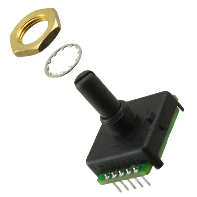


 工商网监
湘ICP备2023018690号
工商网监
湘ICP备2023018690号
