Features
n RoHS compliant*
n HCMOS, CMOS and TTL compatible
Additional Information
Click these links for more information:
n Compact package size
n High rotational cycle life
n Standard or high force push switch option
PRODUCT TECHNICAL INVENTORY SAMPLES
LIBRARY
CONTACT
n Optional detent
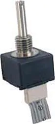
EM14 – 14 mm Rotary Optical Encoder w/Switch
Electrical Characteristics
Electrical Output........................................................................................................................................................................................ 2-bit quadrature code
Resolution........................................................................................................................................................................... 8 to 64 pulses per revolution (PPR)
Supply Voltage (VCC)................................................................................................................................................................................ 5.0 VDC ± 0.25 VDC
Supply Current (ICC).........................................................................................................................................................................................26 mA maximum
Output Voltage
Low (VCE(sat)), per Channel..................................................................................................................................... 800 mV maximum at I(SINK) = 25 mA
High (VO(HI)), per Channel...................................................................................................................................... 4.0 VDC minimum @ VCC = 4.75 VDC
Output Current I(SINK), per Channel................................................................................................................................................................25 mA maximum
Rise/Fall Time......................................................................................................................................................................................................200 ns typical**
Power Dissipation..........................................................................................................................................................................................167 mW maximum
Pulse Width (per Channel)..................................................................................................................................................................................... 180 °e typical
Phase Angle (Channel A Leads Channel B, Clockwise Rotation)..........................................................................................................................90 °e ± 45 °e
Insulation Resistance @ 500 VDC..................................................................................................................................................... 1,000 megohms minimum
Operating RPM ....................................................................................................................................................................................................120 maximum
Switch Power Rating...............................................................................................................................................12 VDC / 20 mA (600 ohms minimum load)
Switch Contact Resistance......................................................................................................................................................................... 200 ohms maximum
Environmental Characteristics
Operating Temperature Range @ 5.0 VDC....................................................................................................................... -40 °C to +70 °C (-40 °F to +158 °F)
Storage Temperature Range............................................................................................................................................ -55 ºC to +125 ºC (-67 °F to +257 °F)
Vibration...............................................................................................................................................................................................................................15 G
Shock...................................................................................................................................................................................................................................50 G
Humidity....................................................................................................................................................................... MIL-STD-202, Method 103, Condition B
Flammability............................................................................................................................................................................................. Conforms to UL 94HB
IP Rating.......................................................................................................................................................................................................................... IP 54***
Mechanical Characteristics
Mechanical Angle.............................................................................................................................................................................................360 ° Continuous
Torque
Starting/Running................................................................................................................................................................ 1.06 N-cm (1.5 oz.-in.) maximum
Detent.........................................................................................................................................................................................1.2 N-cm (1.7 oz.-in.) typical
Rotational Life
Non-detent (@ 30 RPM)........................................................................................................................................1,000,000 cycles (2,000,000 revolutions)
With detent (@ 30 RPM)..............................................................................................................................................100,000 cycles (200,000 revolutions)
Switch Life............................................................................................................................................................................................................100,000 cycles
Switch Actuation Force
Standard.......................................................................................................................................................................................... 250 gm (8.82 oz.) typical
High Force..................................................................................................................................................................................... 850 gm (29.98 oz.) typical
Switch Travel
Standard...........................................................................................................................................................................................................0.04 in. typical
High Force......................................................................................................................................................................................................0.025 in. typical
Shaft Radial Play........................................................................................................................................................................................... 0.005 in. maximum
Shaft Axial Structural Strength.......................................................................................................................................................................... 35 lbs. minimum
Mounting Torque............................................................................................................................................................................2.0 N-m (18 lb.-in.) maximum
Materials and Finishes
Terminals.........................................................................................................................................................................................................Sn plated PC pins
Soldering Condition
Manual Soldering..................................................................................................................... 96.5Sn/3.0Ag/0.5Cu solid wire or no-clean rosin cored wire
370 °C (700 °F) max. for 3 seconds
Wave Soldering.............................................................................................................................................. 96.5Sn/3.0Ag/0.5Cu solder with no-clean flux
260 °C (500 °F) max. for 5 seconds
Wash processes........................................................................................................................................................................................Not recommended
Mounting Hardware
Nut...............................................................................................................................Black annodized brass, hex (metric)/Nickel-plated brass, hex (SAE)
Lockwasher............................................................................................................................................................. Nickel-plated spring steel, internal tooth
Marking.....................................................................................................Manufacturer’s symbol, model number, product code, terminal style and date code
Standard Packaging.......................................................................................................................................................... Anti-static plastic tube (25 pcs./tube)
**See schematic note page 5.
***When device is mounted by normal mounting means.
WARNING Cancer and Reproductive Harm
www.P65Warnings.ca.gov
*RoHS Directive 2015/863, Mar 31, 2015 and Annex.
Specifications are subject to change without notice.
Users should verify actual device performance in their specific applications.
The products described herein and this document are subject to specific legal disclaimers as set forth on the last
page of this document, and at www.bourns.com/docs/legal/disclaimer.pdf.
�Additional Features
n Splashproof shaft seal
n Recommended for human/machine interface applications (HMI)
n Cable/connector option
n Optional bracket
EM14 – 14 mm Rotary Optical Encoder w/Switch
Part Numbering System
E M 1 4 A 0 D - C 2 4
-
L 0 3 2 S
MODEL NO. DESIGNATOR
EM14 14 mm Rotary Optical Encoder
Code
A
C
R
Code
S
H
N
BUSHING DESIGNATOR
Description
3/8 " D x 3/8 " L Threaded
1/4 " D x 1/4 " L Threaded
10 mm D x 9.5 mm L Threaded
RESOLUTION (Pulses Per Revolution)
Code Description
08
8 PPR
16
16 PPR
32
32 PPR
64
64 PPR
DETENT OPTION
Code Description
0
No Detent
1
32 Detents (Available for
8 or 32 PPR only)
ANTI-ROTATION LUG/BRACKET OPTION
Code Description
A
A/R Lug
B
Bracket (No hardware/no cable or
connector)
D
None
SHAFT STYLE (See Outline Drawing for Details)
Code
B
C
E
R
M
Description
1/4 " Dia. Slotted End
1/4 " Dia. Flatted End
1/8 " Dia. Slotted End
6 mm Dia. Slotted End
6 mm Dia. Flatted End
Code
24
28
20
25
SWITCH OPTION
Description
Push Switch (Standard)
Push Switch (High Force)
No Switch
Available w/
Bushing
A
A
C
R
R
SHAFT LENGTH DESIGNATOR
Length (FMS)
Available w/Bushing
3/4 "
A, C
7/8 "
A, C
20 mm
R
25 mm
R
CABLE/CONNECTOR OPTION
Code Description
0
No Cable/Connector
6 ” Cable with Female Connector
1
and stripped/tinned leads
6 ” Cable with Female Connector
2
on both ends
12 ” Cable with Female Connector
3
and stripped/tinned leads
12 ” Cable with Female Connector
4
on both ends
3 ” Cable with Female Connector and
5
stripped/tinned leads
1.5 ” Cable with Female Connector and
6
stripped/tinned leads
2 ” Cable with Female Connector and
7
stripped/tinned leads
5 ” Cable with Female Connector and
8
stripped/tinned leads
Connector options 1~8 are currently available, but not
recommended for new designs. See Product Obsolescence
Memo.
For other cable and connector options, please contact the factory.
TERMINAL CONFIGURATION
Code Description
L
Axial Multi-Purpose Pin
R
Radial Multi-Purpose Pin
Specifications are subject to change without notice.
Users should verify actual device performance in their specific applications.
The products described herein and this document are subject to specific legal disclaimers as set forth on the last page of this document, and at www.bourns.com/docs/legal/disclaimer.pdf.
�
EM14 – 14 mm Rotary Optical Encoder w/Switch
Product Dimensions
MOUNTING
SURFACE
14.25
(0.561)
10.03
(.395)
L
3.18
TYP.
(.125)
"L" PIN STYLE
9.53
(.375)
F
4.76
(.187)
14.76
(.581)
DIA.
0.457 ± 0.026
(.018 ± .001)
8.00
(.315)
METAL SHAFT
(SEE TABLE FOR OPTIONS)
1.19
.79
X
HIGH
(.047) (.031)
ANTI-ROTATION BOSS
(OPTIONAL)
R
2.08
TYP.
(.082)
"R" PIN STYLE
METAL BUSHING
(SEE TABLE FOR OPTIONS)
1.75
(.069)
"L" PIN STYLE
TYP.
1.52
(.060)
"R" PIN STYLE
TYP.
Shaft / Flat Length Dimensions
"A" Style Bushing - Flatted Shafts
L
L
9.53
(.375)
F
4.76
(.187)
BUSHING
DIA.
6.35
(.250)
9.52
(.375)
SHAFT LENGTH FLAT LENGTH
"L"
"F"
19.05
7.94
(.750)
(.313)
22.22
9.52
(.875)
(.375)
"A" Style Bushing - Slotted Shafts
1.8
(.071)
L
F
4.42
(.174)
3/8-32 UNEF-2A
SHAFT
DIA.
"R" Style Bushing - Flatted Shafts
"C" Style Bushing - Slotted Shafts
9.5
(.374)
1.52
(.060)
0.79
(.031)
L
6.35
(.250)
1/4-32 UNEF-2A
M10 x 0.75-6 g
SHAFT
DIA.
BUSHING
DIA.
6.0
(.236)
10.0
(.394)
SHAFT LENGTH FLAT LENGTH
"L"
"F"
20.0
7.0
(.787)
(.275)
25.0
12.0
(.984)
(.472)
SHAFT
DIA.
BUSHING
DIA.
3.17
(.125)
6.35
(.250)
"R" Style Bushing - Slotted Shafts
1.8
(.071)
9.53
(.375)
L
9.5
(.374)
DIMENSIONS:
0.99
(.040)
0.99
(.040)
3/8-32 UNEF-2A
SHAFT
DIA.
BUSHING
DIA.
6.35
(.250)
9.52
(.375)
SHAFT LENGTH
"L"
19.05
(.750)
22.22
(.875)
SHAFT LENGTH
"L"
19.05
(.750)
22.22
(.875)
MM
(INCHES)
M10 x 0.75-6 g
SHAFT
DIA.
BUSHING
DIA.
6.0
(.236)
10.0
(.394)
SHAFT LENGTH
"L"
20.0
(.787)
25.0
(.984)
Specifications are subject to change without notice.
Users should verify actual device performance in their specific applications.
The products described herein and this document are subject to specific legal disclaimers as set forth on the last page of this document, and at www.bourns.com/docs/legal/disclaimer.pdf.
"U" Style Bushing - Slotted Shafts
�STRIPPED AND TINNED
100 % MATTE TIN
RIBBON CABLE
6x28 AWG x 1.25 PITCH
(.049)
PIN 1 RED STRIPE
REF.
8.0
(.315)
.457
FOR (.018) DIA. PINS
123456
2.54 ± 0.4
(.100 ± .016)
6.0 ± 0.2
(.236 ± .008)
A
8.75 ± 0.2
(.344 ± .008)
EM14 – 14 mm Rotary Optical Encoder w/Switch
RIBBON CABLE
6x28 AWG x 1.25 PITCH
(.049)
PIN 1 - RED STRIPE
123456
654321
A
Cable/Connector Options
6.0
1.0
x
(.236) (.039)
1.25
x
PITCH RECEPTACLE
(.049)
.457
FOR (.018) DIA. PINS
Cable Assembly, Connector on One End
STRIPPED AND TINNED
100 % MATTE TIN
CONNECTOR
RIBBON CABLE
6x28 AWG x 1.25 PITCH
(.049)
PIN 1 RED STRIPE
REF.
8.0
(.315)
123456
2.54 ± 0.4
(.100 ± .016)
6.0 ± 0.2
(.236 ± .008)
A
8.75 ± 0.2
(.344 ± .008)
2 x CONNECTOR
Cable Assembly, Connector on Both Ends
PIN 1 - RED STRIPE
RIBBON CABLE
6x28 AWG x 1.25 PITCH
(.049)
2.9
(.114)
3.5 ± 0.2
(.138 ± .008)
6.0
1.0
x
(.236) (.039)
1.25
PITCH RECEPTACLE
(.049)
.457
FOR (.018) DIA. PINS
x
123456
654321
HDW.
NO.
DESCRIPTION
“A” DIM.
H-290-1
CABLE ASSEMBLY,
CONNECTOR ON BOTH ENDS
152.4 ± 5.0
(6.0 ± .197)
H-290-2
CABLE ASSEMBLY,
CONNECTOR ON ONE END
304.8 ± 5.0
(12.0 ± .197)
H-290-3
304.8 ± 5.0
CABLE ASSEMBLY,
CONNECTOR ON BOTH ENDS (12.0 ± .197)
H-290-4
CABLE ASSEMBLY,
CONNECTOR ON ONE END
152.4 ± 5.0
(6.0 ± .197)
H-290-5
RIBBON CABLE, 28 AWG,
CONNECTOR ON ONE END
76.2 ± 5.0
(3.0 ± .197)
H-290-6
RIBBON CABLE, 28 AWG,
CONNECTOR ON ONE END
38.1 ± 5.0
(1.5 ± .197)
H-290-7
RIBBON CABLE, 28 AWG,
CONNECTOR ON ONE END
50.8 ± 5.0
(2.0 ± .197)
H-290-8
RIBBON CABLE, 28 AWG,
CONNECTOR ON ONE END
127 ± 5.0
(5.0 ± .197)
A
Terminal Configurations
HDW.
DESCRIPTION
“A” DIM.
CABLE ASSEMBLY,
CONNECTOR ON BOTH ENDS
152.4 ± 5.0
(6.0 ± .197)
NO.
Radial (shown with optional mounting
bracket)
14.99 ± .13
(.590 ± .005)
H-290-1
CABLE ASSEMBLY,
H-290-2
14.76 ± .25
CONNECTOR ON ONE END
(.581 ± .010)
H-290-3
2.62 ± .38
(.103 ± .015)
17.17
REF.
(.676)
RIBBON CABLE, 28 AWG,
CONNECTOR ON ONE END
Axial (shown with optional mounting
bracket)
RIBBON
CABLE, 28 AWG,
14.99 ± .25
(.590 ± .010)
1.24
152.4 ± 5.0
(.049)
(6.07.87
± .197)
(.310)
REF.
76.2 ± 5.0
(3.0 ± .197)
38.1 ± 5.0
(1.5 ± .197)
H-290-7
RIBBON CABLE, 28 AWG,
CONNECTOR ON ONE END
50.8 ± 5.0
(2.0 ± .197)
H-290-8
RIBBON CABLE, 28 AWG,
CONNECTOR ON ONE END
127 ± 5.0
(5.0 ± .197)
1.22
(.048)
2.49 ± .38
(.098 ± .015)
17.17
(.676)
DIA.
1.73 ± .10
(.068 ± .004)
2 PLCS.
304.8 ± 5.0
15.16
± .25
(12.0
± .197)
(.597 ± .010)
CONNECTOR ON ONE END
H-290-6
Recommended PCB Layout
304.8 ± 5.0
CABLE ASSEMBLY,
CONNECTOR ON BOTH ENDS (12.0 ± .197)
1.60
1.5
WIDE
(.063)
CABLE ASSEMBLY,
(.059)
H-290-4 REF.
CONNECTOR
ON ONE END
0.381
PCB
X
THICK
THICKNESS
(.015)
H-290-5
6.0
1.
x
(.236) (.03
1.25
x
PITCH RECEPTAC
(.049)
.457
FOR (.018) DIA. PINS
2 x CONNECTOR
Cable Assembly, Connector on Both Ends
2.9
(.114
3.5
(.138
10.57
(.416)
REF.
6.25
(.246)
1.60
(.063)
REF.
PCB THICKNESS
DIA.
.64
6 PLCS.
(.025)
GROUND
CHANNEL “A”
7.87 ± .08
(.310 ± .003)
1.27 ± .13
(.050 ± .005)
5 PLCS.
CHANNEL “B”
POWER
MOMENTARY
SWITCH
Recommended PCB Layout
14.61
(.575)
GROUND
CHANNEL “A”
CHANNEL “B”
POWER
DIA.
.64
(.025)
6 PLCS.
MOMENTARY
SWITCH
DIMENSIONS:
DIA.
1.73 ± .10
(.068 ± .004)
2 PLCS.
6.25 ± .08
(.246 ± .003)
1.27 ± .13
(.050 ± .005)
5 PLCS.
MM
(INCHES)
Specifications are subject to change without notice.
Users should verify actual device performance in their specific applications.
The products described herein and this document are subject to specific legal disclaimers as set forth on the last page of this document, and at www.bourns.com/docs/legal/disclaimer.pdf.
CHAN
CHAN
�
EM14 – 14 mm Rotary Optical Encoder w/Switch
14 mm Optical Encoder Electrical Diagram
Quadrature Output
GROUND
CHANNEL A
RED
CW
-
*
90 °e ± 45 °e
22 nF
A
CHANNEL A
CHANNEL B
High
Low
High
Low
180 °e
1 pulse width
SWITCH
TERMINAL
1
OPTO
ASIC
10k
*
1 KΩ
*
32 DETENT / 8 PPR
22 nF
CW
2
SWITCH
TERMINAL
CHANNEL A
10k
POWER
+
CHANNEL B
*
1 KΩ
B
CHANNEL B
32 DETENT / 32 PPR
*External pull-up resistors (1K ohms) and filter caps (22 nF) recommended for proper operation.
Utilization of a filter circuit will yield a typical rise time of 50 microseconds. See schematic.
Terminal Diagram
CW
High
CHANNEL A
Low
CHANNEL B
High
Low
Detent Range
Nominal Detent
Position
1. Nominal detent position occurs when both Channel A and B are in
low states.
CHANNEL "A"
CHANNEL "B"
GROUND
2. Channel A leads Channel B in CW direction and lags in CCW
direction.
A12 +B
TYP. 1.27
(.050)
POWER
MOMENTARY SWITCH
Asia-Pacific: Tel: +886-2 2562-4117 • Email: asiacus@bourns.com
Europe: Tel: +36 88 885 877 • Email: eurocus@bourns.com
The Americas: Tel: +1-951 781-5500 • Email: americus@bourns.com
www.bourns.com
REV. 09/21
Specifications are subject to change without notice.
Users should verify actual device performance in their specific applications.
The products described herein and this document are subject to specific legal disclaimers as set forth on the last page of this document, and at www.bourns.com/docs/legal/disclaimer.pdf.
�Legal Disclaimer Notice
This legal disclaimer applies to purchasers and users of Bourns® products manufactured by or on behalf of Bourns, Inc. and
P[Z�HɉSPH[LZ��JVSSLJ[P]LS`��¸)V\YUZ¹��
Unless otherwise expressly indicated in writing, Bourns® products and data sheets relating thereto are subject to change
^P[OV\[�UV[PJL���


 工商网监
湘ICP备2023018690号
工商网监
湘ICP备2023018690号
