Features
Applications
■
4.5 mm SMD
Fast tripping resettable circuit protection
Surface mount packaging for automated
assembly
Reduced component size and resistance
■
Agency recognition:
■
■
■
High Density Circuit Board Applications:
■ Hard disk drives
■ PC motherboards
■ PC peripherals
■ Point-of-sale (POS) equipment
■ PCMCIA cards
T V Rheinland
MF-MSMD Series - PTC Resettable Fuses
Electrical Characteristics
Ihold
Model
V max.
Volts
I max.
Amps
MF-MSMD010
MF-MSMD014
MF-MSMD020
MF-MSMD030
MF-MSMD050
MF-MSMD075
MF-MSMD110
MF-MSMD125
MF-MSMD150
MF-MSMD160
MF-MSMD200
MF-MSMD260
60.0
60.0
30.0
30.0
15.0
13.2
6.0
6.0
6.0
8.0
6.0
6.0
40
40
80
10
100
100
100
100
100
100
100
100
Itrip
Amperes
at 23 °C
Hold
Trip
0.10
0.14
0.20
0.30
0.50
0.75
1.10
1.25
1.50
1.60
2.00
2.60
0.30
0.34
0.40
0.60
1.00
1.50
2.20
2.50
3.00
2.80
4.00
5.20
Resistance
Ohms
at 23 °C
RMin.
R1Max.
0.70
0.40
0.40
0.30
0.15
0.11
0.04
0.035
0.03
0.035
0.020
0.015
15.00
6.50
6.00
3.00
1.00
0.45
0.21
0.14
0.120
0.099
0.100
0.080
Max. Time
To Trip
Amperes
at 23 °C
Seconds
at 23 °C
0.5
1.5
6.0
8.0
8.0
8.0
8.0
8.0
8.0
8.0
8.0
8.0
1.5
0.15
0.06
0.10
0.15
0.20
0.30
0.4
0.5
2.0
3.0
5.0
Tripped
Power
Dissipation
Watts
at 23 °C
Typ.
1.0
1.0
1.0
1.2
1.2
1.2
1.2
1.5
1.5
1.5
1.5
1.5
Environmental Characteristics
Operating/Storage Temperature ........................-40 °C to +85 °C
Maximum Device Surface Temperature
in Tripped State ................................................125 °C
Passive Aging......................................................+85 °C, 1000 hours ....................................±5 % typical resistance change
Humidity Aging....................................................+85 °C, 85 % R.H. 1000 hours....................±5 % typical resistance change
Thermal Shock ....................................................+85 °C to -40 °C, 20 times ..........................±10 % typical resistance change
Solvent Resistance ............................................MIL-STD-202, Method 215 ........................No change
Vibration ..............................................................MIL-STD-883C, Method 2007.1, ................No change
Condition A
Test Procedures And Requirements For Model MF-MSMD Series
Test
Test Conditions
Accept/Reject Criteria
Visual/Mech.....................................Verify dimensions and materials ....................................Per MF physical description
Resistance ......................................In still air @ 23 °C ............................................................Rmin ≤ R ≤ R1max
Time to Trip ....................................At specified current, Vmax, 23 °C ..................................T ≤ max. time to trip (seconds)
Hold Current....................................30 min. at Ihold ..............................................................No trip
Trip Cycle Life ................................Vmax, Imax, 100 cycles ..................................................No arcing or burning
Trip Endurance ................................Vmax, 48 hours ..............................................................No arcing or burning
Solderability ....................................MIL-STD-202F, Method 208F..........................................95 % min. coverage
UL File Number ..................................E174545
http://www.ul.com/ Follow link to Certifications, then UL File No., enter E174545
CSA File Number ................................CA110338
http://directories.csa-international.org/ Under “Certification Record” and “File Number” enter 110338-0-000
TÜV Certificate Number......................R 02057213
http://www.tuvdotcom.com/ Follow link to “other certificates”, enter File No. 2057213
Specifications are subject to change without notice.
Customers should verify actual device performance in their specific applications.
�Additional Features
■
Patents pending
MF-MSMD Series - PTC Resettable Fuses
Product Dimensions
A
Model
Min.
4.37
(0.172)
4.37
(0.172)
4.37
(0.172)
4.37
(0.172)
4.37
(0.172)
4.37
(0.172)
4.37
(0.172)
4.37
(0.172)
4.37
(0.172)
4.37
(0.172)
4.37
(0.172)
4.37
(0.172)
MF-MSMD010
MF-MSMD014
MF-MSMD020
MF-MSMD030
MF-MSMD050
MF-MSMD075
MF-MSMD110
MF-MSMD125
MF-MSMD150
MF-MSMD160
MF-MSMD200
MF-MSMD260
B
Max.
4.73
(0.186)
4.73
(0.186)
4.73
(0.186)
4.73
(0.186)
4.73
(0.186)
4.73
(0.186)
4.73
(0.186)
4.73
(0.186)
4.73
(0.186)
4.73
(0.186)
4.73
(0.186)
4.73
(0.186)
Min.
3.07
(0.121)
3.07
(0.121)
3.07
(0.121)
3.07
(0.121)
3.07
(0.121)
3.07
(0.121)
3.07
(0.121)
3.07
(0.121)
3.07
(0.121)
3.07
(0.121)
3.07
(0.121)
3.07
(0.121)
C
Max.
3.41
(0.134)
3.41
(0.134)
3.41
(0.134)
3.41
(0.134)
3.41
(0.134)
3.41
(0.134)
3.41
(0.134)
3.41
(0.134)
3.41
(0.134)
3.41
(0.134)
3.41
(0.134)
3.41
(0.134)
Min.
0.56
(0.022)
0.56
(0.022)
0.56
(0.022)
0.56
(0.022)
0.38
(0.015)
0.38
(0.015)
0.38
(0.015)
0.30
(0.012)
0.30
(0.012)
0.30
(0.012)
0.30
(0.012)
0.25
(0.010)
Max.
0.81
(0.032)
0.81
(0.032)
0.81
(0.032)
0.81
(0.032)
0.62
(0.024)
0.62
(0.024)
0.62
(0.024)
0.48
(0.019)
0.48
(0.019)
0.48
(0.019)
0.48
(0.019)
0.48
(0.019)
Packaging: 2000 pcs. per reel.
Top and Bottom View
UNIT =
Side View
A
MM
(INCHES)
Solder Reflow Recommendations
C
300
Preheating
Soldering
Cooling
10–20
120
250
Temperature (°C)
B
D
Recommended Pad Layout
1.5 ± 0.05
(.059 ± .002)
D
Min.
0.30
(0.012)
0.30
(0.012)
0.30
(0.012)
0.30
(0.012)
0.30
(0.012)
0.30
(0.012)
0.30
(0.012)
0.30
(0.012)
0.30
(0.012)
0.30
(0.012)
0.30
(0.012)
0.30
(0.012)
1.5 ± 0.05
(.059 ± .002)
200
150
100
50
0
3.2 ± 0.1
(0.126 ± .004)
160–220
2.70 ± 0.1
(.106 ± .004)
Terminal material: solder-plated copper
Termination pad solderability: Meets EIA
Specification RS-186-9E, ANSI/J-STD-002
Category 3.
Time (seconds)
Note:
• MF-MSMD models can be wave soldered and reworked.
• If reflow temperatures exceed the recommended profile, devices may not meet the performance
requirements.
Specifications are subject to change without notice.
Customers should verify actual device performance in their specific applications.
�MF-MSMD Series - PTC Resettable Fuses
How to Order
Typical Time to Trip at 23 ˚C
MF - MSMD 075 - 2
100
Multifuse® Product
Designator
MF-MSMD200
Series
MSMD = 4.5 mm Surface Mount
Component
MF-MSMD010
Time to Trip (Seconds)
10
Hold Current, Ihold
010-260 (0.10 Amps - 2.60 Amps)
MF-MSMD030
Packaging
Packaged per EIA 481-1
-2 = Tape and Reel
1
Typical Part Marking
0.1
Represents total content. Layout may vary.
PART
IDENTIFICATION
MF-MSMD260
MF-MSMD160
MF-MSMD014
0.01
MF-MSMD150
MF-MSMD125
MF-MSMD110
MF-MSMD075
MF-MSMD020
MANUFACTURER'S
TRADEMARK
075
0A
DATE CODE WEEK 1 OF 2000 = 0A
(YEAR & WEEK)
WEEK 27 OF 2000 = A0
(WEEK & YEAR)
MF-MSMD050
0.001
1
0.1
10
100
Fault Current (Amps)
Thermal Derating Chart - Ihold / Itrip (Amps)
Ambient Operating Temperature
Model
MF-MSMD010
MF-MSMD014
MF-MSMD020
MF-MSMD030
MF-MSMD050
MF-MSMD075
MF-MSMD110
MF-MSMD125
MF-MSMD150
MF-MSMD160
MF-MSMD200
MF-MSMD260
-40 ˚C
0.16 / 0.32
0.23 / 0.52
0.29 / 0.58
0.44 / 0.88
0.77 / 1.54
1.15 / 2.30
1.59 / 3.18
1.80 / 3.61
2.17 / 4.34
2.30 / 5.00
3.08 / 6.14
4.00 / 7.98
-20 ˚C
0.14 / 0.28
0.19 / 0.45
0.26 / 0.52
0.39 / 0.78
0.68 / 1.36
1.01 / 2.02
1.43 / 2.86
1.63 / 3.25
1.95 / 3.90
2.20 / 4.40
2.71 / 5.39
3.52 / 7.01
0 ˚C
0.12 / 0.24
0.17 / 0.40
0.23 / 0.46
0.35 / 0.70
0.59 / 1.18
0.88 / 1.76
1.26 / 2.52
1.43 / 2.86
1.72 / 3.44
1.90 / 3.80
2.35 / 4.62
3.06 / 6.09
23 ˚C
0.11 / 0.22
0.14 / 0.34
0.20 / 0.40
0.30 / 0.60
0.50 / 1.00
0.75 / 1.50
1.10 / 2.20
1.25 / 2.50
1.50 / 3.00
1.60 / 2.80
2.00 / 4.01
2.60 / 5.15
40 ˚C
0.08 / 0.16
0.12 / 0.29
0.17 / 0.34
0.26 / 0.52
0.44 / 0.88
0.65 / 1.30
0.95 / 1.90
1.08 / 2.16
1.30 / 2.59
1.45 / 2.90
1.80 / 1.61
2.34 / 4.64
50 ˚C
0.07 / 0.14
0.10 / 0.25
0.15 / 0.30
0.23 / 0.46
0.40 / 0.80
0.60 / 1.20
0.87 / 1.74
0.99 / 1.98
1.18 / 2.37
1.30 / 2.60
1.60 / 3.19
2.08 / 4.13
60 ˚C
0.06 / 0.12
0.09 / 0.23
0.14 / 0.28
0.21 / 0.42
0.37 / 0.74
0.55 / 1.10
0.80 / 1.60
0.91 / 1.82
1.09 / 2.18
1.15 / 2.30
1.50 / 2.98
1.95 / 3.87
70 ˚C
0.05 / 0.10
0.08 / 0.21
0.12 / 0.24
0.18 / 0.36
0.33 / 0.66
0.49 / 0.98
0.71 / 1.42
0.81 / 1.62
0.97 / 1.94
1.03 / 2.06
1.07 / 2.12
1.39 / 2.74
85 ˚C
0.03 / 0.06
0.06 / 0.16
0.10 / 0.20
0.15 / 0.30
0.29 / 0.58
0.43 / 0.86
0.60 / 1.20
0.68 / 1.36
0.82 / 1.64
0.91 / 1.82
0.80 / 1.58
1.04 / 2.05
MF-MSMD SERIES, REV. Q, 02/04
Specifications are subject to change without notice.
Customers should verify actual device performance in their specific applications.
�MF-MSMD, MF-USMD & MF-ESMD Series Tape and Reel Specs
MF-MSMD Series
per EIA-481-1
MF-USMD Series
per EIA 481-1
MF-ESMD Series
per EIA 481-2
W
12.0 ± 0.30
(0.472 ± 0.012)
8.0 ± 0.30
(0.315 ± 0.012)
24.0 ± 0.3
(0.945 ± 0.012)
P0
4.0 ± 0.10
(0.157 ± 0.004)
4.0 ± 0.10
(0.157 ± 0.004)
4.0 ± 0.1
(0.157 ± 0.004)
P1
P2
8.0 ± 0.10
(0.315 ± 0.004)
2.0 ± 0.05
(0.079 ± 0.002)
A0
3.66 ± 0.15
(0.144 ± 0.006)
B0
4.98 ± 0.10
(0.196 ± 0.004)
Tape Dimensions
4.0 ± 0.10
(0.157 ± 0.004)
2.0 ± 0.05
(0.079 ± 0.002)
MF-USMD005,010,020:
MF-USMD035,050,075,110:
2.93 ± 0.15
2.76 ± 0.10
(0.115 ± 0.006)
(0.109 ± 0.004)
MF-USMD005,010,020:
3.5 ± 0.1
(0.138 ± 0.004)
5.9
(0.232)
1.5 + 0.10/-0.00
(0.059 + 0.004/-0)
5.5 ± 0.05
(0.217 ± 0.002)
1.75 ± 0.10
(0.069 ± 0.004)
B1 max.
D0
F
E1
10.25
(0.404)
0.6
(0.024)
0.1
(0.004)
E2 min.
T max.
T1 max.
0.95 ± 0.10
(0.037 ± 0.004)
K0
Leader min.
Trailer min.
8.0 ± 0.1
(0.315 ± 0.004)
2.0 ± 0.1
(0.079 ± 0.004)
5.65 ± 0.1
(0.222 ± 0.004)
MF-USMD035,050,075,110:
3.56 ± 0.1
(0.140 ± 0.004)
11.86 ± 0.1
(0.467 ± 0.004)
20.1
(0.791)
1.5 + 0.1/-0.0
(0.059 + 0.004/-0)
11.5 ± 0.10
(0.453 ± 0.004)
1.75 ± 0.10
(0.069 ± 0.004)
4.35
(0.171)
1.50 + 0.1/-0.0
(0.059 + 0.004/-0)
3.5 ± 0.05
(0.138 ± 0.002)
1.75 ± 0.10
(0.069 ± 0.004)
6.25
(0.246)
0.6
(0.024)
22.25
(0.876)
0.6
(0.024)
0.1
(0.004)
0.1
(0.004)
MF-USMD005,010,020:
MF-USMD035,050,075,110:
0.75 ± 0.10
1.07 ± 0.10
(0.030 ± 0.004)
(0.042 ± 0.004)
0.85 ± 0.1
(0.033 ± 0.004)
390
(15.35)
160
(6.30)
390
(15.35)
160
(6.30)
390
(15.35)
160
(6.30)
185
(7.28)
50
(1.97)
185
(7.28)
50
(1.97)
8.4 + 1.5/-0.0
(0.331 + 0.059/-0)
14.4
(0.567)
360
(14.17)
60
(2.36)
Reel Dimensions
A max.
N min.
12.4 + 2.0/-0.0
(0.488 + 0.079/-0.0)
18.4
(0.724)
W1
W2 max.
UNIT =
P0
T
D0
24.4 + 2.0/ -0.0
(0.961 + 0.079/-0)
30.4
(1.20)
P2
MM
(INCHES)
E1
W2(MEASURED
AT HUB)
COVER
TAPE
F
E2 W
B1
A
N(HUB DIA.)
B0
K0
T1
P1
A0
W1(MEASURED
AT HUB)
Specifications are subject to change without notice.
Customers should verify actual device performance in their specific applications.
�
很抱歉,暂时无法提供与“MF-MSMD150-2”相匹配的价格&库存,您可以联系我们找货
免费人工找货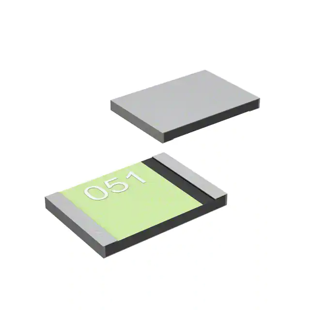


 工商网监
湘ICP备2023018690号
工商网监
湘ICP备2023018690号
