*R
AE **H oHS
C- AL C
Q2 OG OM
00 EN P
CO FR LIA
M EE NT
PL & ,
IA
NT
Features
AUTOMOTIVE
G R A DE
Applications
n Compliant with AEC-Q200 Rev-D- Stress
n Automotive applications
n Where space is limited and fast tripping
Test Qualification for Passive Components
in Automotive Applications
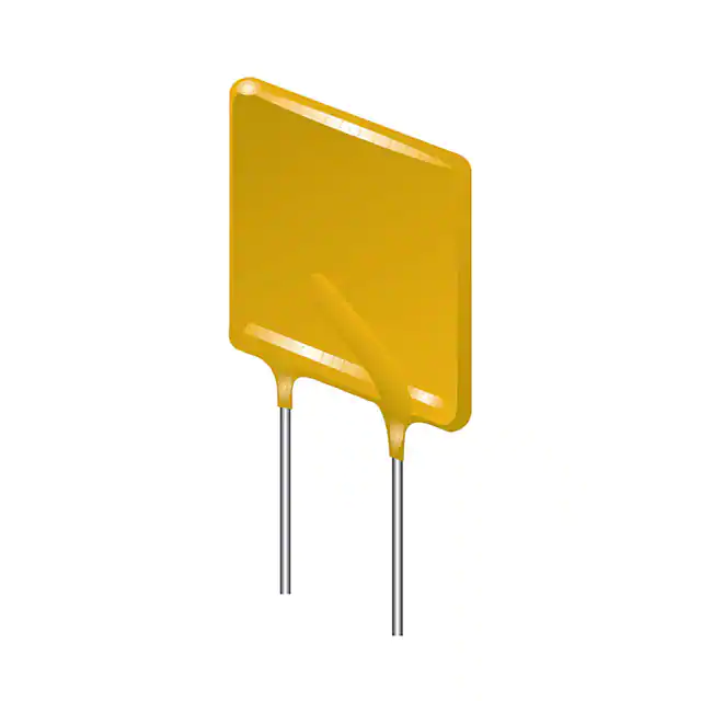
n Radial leaded devices
n Smaller size vs. comparable Ihold ratings
n Faster tripping
n RoHS compliant* and halogen free**
n Agency recognition:
is required
MF-RG Series - PTC Resettable Fuses
Environmental Characteristics
Additional Information
Item
Condition
Click these links for more information:
Criteria
Operating Temperature
-40 °C to +85 °C
Recommended Storage
+40 °C max. / 70 % R.H. max.
Passive Aging
+85 °C, 1000 hours
±5 % typical resistance
change
Humidity Aging
+85 °C, 85 % R.H. 1000 hours
±5 % typical resistance
change
Thermal Shock
-40 °C to +85 °C, 10 times
±10 % typical resistance
change
Solvent Resistance
MIL-STD-202, Method 215
No change
(marking still legible)
Vibration
MIL-STD-883C, Method 2007.1
Condition A
No change
(Rmin < R < R1max)
Moisture Sensitivity Level
(MSL)
See Note
ESD Classification
Class 6 (per AEC-Q200-2, HBM)
PRODUCT TECHNICAL INVENTORY SAMPLES
SELECTOR LIBRARY
CONTACT
Electrical Characteristics
Ihold
Vmax
Imax
Volts
Amps
MF-RG300
16
100
3.0
MF-RG400
16
100
4.0
MF-RG500
16
100
MF-RG600
16
MF-RG650
MF-RG700
Model
Itrip
Initial
Resistance
at 23 °C
Ohms
at 23 °C
Amps
1 Hour (R1)
Post-Trip
Resistance
Max. Time
to Trip
at 23 °C
Ohms
at 23 °C
Tripped
Power
Dissipation
Agency
Recognition
at 23 °C
Watts
cUL
AEC-Q200
Compliant
Min.
Max.
Max.
Amps
Seconds
Typ.
E174545
5.1
0.0380
0.0650
0.0975
15
1.0
2.3
3
3
6.8
0.0210
0.0385
0.0600
20
1.7
2.4
3
3
5.0
8.5
0.0150
0.0230
0.0340
25
2.0
2.6
3
3
100
6.0
10.2
0.0100
0.0185
0.0280
30
3.3
2.8
3
3
16
100
6.5
11.1
0.0088
0.0158
0.0240
33
3.5
3.0
3
3
16
100
7.0
11.9
0.0077
0.0130
0.0200
35
3.5
3.0
3
3
MF-RG800
16
100
8.0
13.6
0.0056
0.0110
0.0175
40
5.0
3.0
3
3
MF-RG900
16
100
9.0
15.3
0.0047
0.0092
0.0135
45
5.5
3.3
3
3
MF-RG1000
16
100
10.0
17.0
0.0040
0.0071
0.0102
50
6.0
3.6
3
3
MF-RG1100
16
100
11.0
18.7
0.0037
0.0062
0.0089
55
7.0
3.7
3
3
WARNING
Cancer and Reproductive Harm
www.P65Warnings.ca.gov
* RoHS Directive 2015/863, Mar 31, 2015 and Annex.
** Bourns considers a product to be “halogen free” if (a) the Bromine (Br) content is 900 ppm or less; (b) the Chlorine (Cl)
content is 900 ppm or less; and (c) the total Bromine (Br) and Chlorine (Cl) content is 1500 ppm or less.
Specifications are subject to change without notice. Users should verify actual device performance in their specific
applications. The products described herein and this document are subject to specific legal disclaimers as set forth on the last
page of this document, and at www.bourns.com/docs/legal/disclaimer.pdf.
�
MF-RG Series - PTC Resettable Fuses
Test Procedures and Requirements
Item
Test Condition
Accept/Reject Criteria
Visual/Mechanical
Verify dimensions and materials
Per MF physical description
Resistance
In still air @ 23 °C
Time to Trip
5 times Ihold, Vmax, 23 °C
Rmin ≤ R ≤ Rmax
Hold Current
T ≤ max. time to trip (seconds)
30 min. at Ihold
Trip Cycle Life
No trip
Vmax, Imax, 100 cycles
Vmax, 48 hours
Trip Endurance
Solderability
No arcing or burning
No arcing or burning
245 °C ±5 °C, 5 seconds
95 % min. coverage
Product Dimensions
Model
MF-RG300
MF-RG400
MF-RG500
MF-RG600
MF-RG650
MF-RG700
MF-RG800
MF-RG900
MF-RG1000
MF-RG1100
A
Max.
B
Max.
7.1
(0.280)
9.9
(0.390)
10.4
(0.409)
10.7
(0.421)
11.2
(0.441)
11.2
(0.441)
12.7
(0.500)
14.0
(0.551)
16.5
(0.650)
17.5
(0.689)
11.0
(0.433)
12.8
(0.504)
14.3
(0.563)
17.1
(0.673)
19.7
(0.776)
19.7
(0.776)
20.9
(0.823)
21.7
(0.854)
25.2
(0.992)
26.0
(1.024)
C
Nom.
5.1
(0.201)
5.1
(0.201)
5.1
(0.201)
5.1
(0.201)
5.1
(0.201)
5.1
(0.201)
5.1
(0.201)
5.1
(0.201)
5.1
(0.201)
5.1
(0.201)
Tol. ±
0.7
(0.028)
0.7
(0.028)
0.7
(0.028)
0.7
(0.028)
0.7
(0.028)
0.7
(0.028)
0.7
(0.028)
0.7
(0.028)
0.7
(0.028)
0.7
(0.028)
D
Min.
E
Max.
F
Nom.
7.6
(0.299)
7.6
(0.299)
7.6
(0.299)
7.6
(0.299)
7.6
(0.299)
7.6
(0.299)
7.6
(0.299)
7.6
(0.299)
7.6
(0.299)
7.6
(0.299)
3.0
(0.118)
3.0
(0.118)
3.0
(0.118)
3.0
(0.118)
3.0
(0.118)
3.0
(0.118)
3.0
(0.118)
3.0
(0.118)
3.0
(0.118)
3.0
(0.118)
0.81
(0.032)
0.81
(0.032)
0.81
(0.032)
0.81
(0.032)
0.81
(0.032)
0.81
(0.032)
0.81
(0.032)
0.81
(0.032)
0.81
(0.032)
0.81
(0.032)
Physical
Characteristics
Style
Wire Material
1
Sn/Cu
1
Sn/Cu
1
Sn/Cu
1
Sn/Cu
1
Sn/Cu
1
Sn/Cu
1
Sn/Cu
1
Sn/Cu
1
Sn/Cu
1
Sn/Cu
DIMENSIONS:
Package 2
Style 1
How to Order
A
E
Typical Part Marking
MF - RG 300 - 0 - 14
Multifuse Product
Designator
Series
RG = Smaller Radial Leaded
Component
Hold Current, Ihold
300-1100 (3.0 Amps - 11.0 Amps)
Packaging Options
- 0 = Bulk Packaging
- 2 = Tape and Reel*
- AP = Ammo-Pak*
Represents total content. Layout may vary.
®
B
D
C
F DIA.
Also available with kinked leads (see How to Order).
MM
(INCHES)
Part Number Suffix Option
- __ = Standard Straight Leads without part
number suffix option
- 14 = �Kinked Leads where straight leads are
standard
*Packaged per EIA-468
PART
IDENTIFICATION
DATE CODE
(LAST DIGIT
OF YEAR &
JULIAN DATE)
MANUFACTURER'S
TRADEMARK
RG300
6180S
LOT NO.
(S = CHINA)
Specifications are subject to change without notice.
Users should verify actual device performance in their
specific applications.
The products described herein and this document are
subject to specific legal disclaimers as set forth on the
last page of this document, and at
www.bourns.com/docs/legal/disclaimer.pdf.
�
MF-RG Series - PTC Resettable Fuses
Thermal Derating Table - Ihold (Amps)
Ambient Operating Temperature
Model
-40 °C
4.4
5.9
7.3
8.8
9.5
10.3
11.7
13.2
14.7
16.1
MF-RG300
MF-RG400
MF-RG500
MF-RG600
MF-RG650
MF-RG700
MF-RG800
MF-RG900
MF-RG1000
MF-RG1100
-20 °C
4.0
5.3
6.6
8.0
8.6
9.3
10.7
11.9
13.3
14.6
0 °C
3.6
4.8
6.0
7.2
7.8
8.4
9.6
10.7
12.0
13.1
23 °C
3.0
4.0
5.0
6.0
6.5
7.0
8.0
9.0
10.0
11.0
40 °C
2.6
3.5
4.4
5.2
5.7
6.2
6.9
7.9
8.7
9.7
50 °C
2.4
3.2
4.0
4.8
5.2
5.6
6.4
7.2
8.0
8.8
60 °C
2.1
2.8
3.6
4.2
4.6
5.0
5.6
6.4
7.0
7.8
70 °C
1.9
2.5
3.1
3.8
4.1
4.4
5.1
5.6
6.3
6.9
85 °C
1.4
1.9
2.4
2.8
3.0
3.3
3.7
4.2
4.7
5.2
Itrip is approximately two times Ihold.
Typical Time to Trip at 23 °C
MF-RG650
MF-RG600
MF-RG500
MF-RG400
MF-RG300
MF-RG700
MF-RG800
MF-RG900
MF-RG1000
MF-RG1100
Time to Trip (Seconds)
1000
100
10
1
0.1
0.01
0.001
1
10
100
Fault Current (Amps)
Packaging Quantity
Packaging options
Models
Unit Quantity (Pcs.)
Unit
Bulk
All models
MF-RG300 ~ MF-RG500
MF-RG600 ~ MF-RG1100
MF-RG300 ~ MF-RG500
MF-RG600 ~ MF-RG1100
500
3000
1000
2000
1000
Bag
Tape & Reel
Ammo-Pack
Reel
Pack
Specifications are subject to change without notice.
Users should verify actual device performance in their specific applications.
The products described herein and this document are subject to specific legal disclaimers as set forth on the last page of this document, and at www.bourns.com/docs/legal/disclaimer.pdf.
�
MF-RG Series Tape and Reel Specifications
Devices taped using EIA-468/IEC 60286-2 standards. See table below and figures for details.
IEC
Mark
EIA
Mark
Carrier tape width
W
Hold down tape width
W0
Dimension Description
Dimensions
Tolerance
W
18
(.709)
+1.0/-0.5
(+.039/-.020)
W0
5
(.197)
min.
Hold down tape
No protrusion
Adhesive tape position
W2
W2
3
(.118)
max.
Sprocket hole position
W1
W1
9
(.354)
+0.75-0.5
(+.030/-.020)
Sprocket hole diameter
D0
D0
4
(.157)
±0.2
(±.0078)
Height to seating plane (straight lead)
H
H
18 ~ 20
(.709 ~ .787)
Height to seating plane (formed lead)
H0
H0
16
(.630)
±0.5
(±.020)
Overall height above abscissa: MF-RG300 ~ MF-RG800
H1
H1
38.5
(1.516)
max.
Overall height above abscissa: MF-RG900 ~ MF-RG1100
H1
H1
43.5
(1.713)
max.
L
11
(.433)
max.
Cutout length
Sprocket hole pitch
P0
P0
12.7
(.500)
±0.3
(±.012)
Device pitch: MF-RG300 ~ MF-RG500
P
P
12.7
(.500)
±0.3
(±.012)
Device pitch: MF-RG600 ~ MF-RG1100
P
P
25.4
(1.00)
±0.6
(±.024)
20 consecutive
±1
(±.039)
Pitch tolerance
Composite tape thickness
t
t
0.9
(.035)
max.
Overall tape and lead thickness
t1
t1
2.3
(.091)
max.
0
±0.3
(±.012)
Splice sprocket hole alignment
Front-to-back deviation
Δh
Δh
0
±1.0
(±.039)
Side-to-side deviation
Δp
Δp
0
±1.3
(±.051)
Ordinate to adjacent component lead
P1
P1
3.81
(.150)
±0.7
(±.028)
Lead spacing
F
F
5.08
(.200)
+0.6/-0.2
(+.024/-.008)
— Continued on next page —
DIMENSIONS:
MM
(INCHES)
Specifications are subject to change without notice.
Users should verify actual device performance in their specific applications.
The products described herein and this document are subject to specific legal disclaimers as set forth on the last page of this document, and at www.bourns.com/docs/legal/disclaimer.pdf.
�
MF-RG Series Tape and Reel Specifications
IEC
Mark
EIA
Mark
Reel width including flanges and hub
W4
w2
Dimension between flanges (measured at hub)
W3
w1
A
a
Dimension Description
Reel diameter
Space between flanges (at hub, excluding device)
Dimensions
370.0
(14.57)
max.
4.75
(.187)
±3.25
(±.128)
±12.0
(±.472)
C
c
26.0
(1.024)
Core diameter
N
n
80
(3.15)
Box dimensions
h
62 x 372 x 372
(2.44 x 14.6 x 14.6)
Consecutive missing places
Empty places per reel
A
B
W0
h
H0
max.
p
max.
Less than 0.1 %
F
L
min.
p
3
Reference plane
P1
H1
Taped Component Dimensions per EIA Mark h
Figure 1
max
allow proper reeling and unreeling
Arbor hole diameter
h
Tolerance
62.0
(2.44)
H
W1
H1
DIMENSIONS:
MM
(INCHES)
p
W
p
Applies to Models:
I2
MF-RG300 ~ MF-RG1100
H1
I1
P0
Reference
plane
D0
P1
User direction of feed
H1
Cross section A - B
H
F W2
A
L
B
P0
W0
H0
W1
W
D0
t
User direction of feed
Cross section A - B
t1
Reel Dimensions - per EIA Mark Figure 2
Reel
Applies to Models:
Upper side
n
MF-RG300 ~ MF-RG1100
t
a
c
User
direction
of
feed
Tape
Lower side
w1
w2
MF-RG SERIES, REV. Q, 03/22
Specifications are subject to change without notice.
Users should verify actual device performance in their specific applications.
The products described herein and this document are subject to specific legal disclaimers as set forth on the last page of this document, and at www.bourns.com/docs/legal/disclaimer.pdf.
�
Bourns
PPTC Resettable
Fuses
3312
- ®2 Multifuse
mm SMD® Trimming
Potentiometer
Application Notice
• Users are responsible for independent and adequate evaluation of Bourns® Multifuse® Polymer PTC devices in the user’s
application, including the PPTC device characteristics stated in the applicable data sheet.
•
Polymer PTC devices must not be allowed to operate beyond their stated maximum ratings. Operation in excess of such
maximum ratings could result in damage to the PTC device and possibly lead to electrical arcing and/or fire. Circuits with
inductance may generate a voltage above the rated voltage of the polymer PTC device and should be thoroughly evaluated
within the user’s application during the PTC selection and qualification process.
• Polymer PTC devices are intended to protect against adverse effects of temporary overcurrent or overtemperature
conditions up to rated limits and are not intended to serve as protective devices where overcurrent or overvoltage conditions
are expected to be repetitive or prolonged.
•
In normal operation, polymer PTC devices experience thermal expansion under fault conditions. Thus, a polymer PTC
device must be protected against mechanical stress, and must be given adequate clearance within the user’s application to
accommodate such thermal expansion. Rigid potting materials or fixed housings or coverings that do not provide adequate
clearance should be thoroughly examined and tested by the user, as they may result in the malfunction of polymer PTC
devices if the thermal expansion is inhibited.
• Exposure to lubricants, silicon-based oils, solvents, gels, electrolytes, acids, and other related or similar materials may
adversely affect the performance of polymer PTC devices.
•
Aggressive solvents may adversely affect the performance of polymer PTC devices. Conformal coating, encapsulating,
potting, molding, and sealing materials may contain aggressive solvents including but not limited to xylene and toluene,
which are known to cause adverse effects on the performance of polymer PTCs. Such aggressive solvents must be
thoroughly cured or baked to ensure their complete removal from polymer PTCs to minimize the possible adverse effect
on the device.
• Recommended storage conditions should be followed at all times. Such conditions can be found on the applicable data
sheet and on the Multifuse® Polymer PTC Moisture/Reflow Sensitivity Classification (MSL) note:
https://www.bourns.com/docs/RoHS-MSL/msl_mf.pdf
MFAN 12/18
Specifications are subject to change without notice.
Users should verify actual device performance in their specific applications.
The products described herein and this document are subject to specific legal disclaimers as set forth on the last page of this document, and at www.bourns.com/docs/legal/disclaimer.pdf.
�
Legal Disclaimer Notice
This legal disclaimer applies to purchasers and users of Bourns® products manufactured by or on behalf of Bourns, Inc. and its
affiliates (collectively, “Bourns”).
Unless otherwise expressly indicated in writing, Bourns® products and data sheets relating thereto are subject to change
without notice. Users should check for and obtain the latest relevant information and verify that such information is current and
complete before placing orders for Bourns® products.
The characteristics and parameters of a Bourns® product set forth in its data sheet are based on laboratory conditions, and
statements regarding the suitability of products for certain types of applications are based on Bourns’ knowledge of typical
requirements in generic applications. The characteristics and parameters of a Bourns® product in a user application may vary
from the data sheet characteristics and parameters due to (i) the combination of the Bourns® product with other components
in the user’s application, or (ii) the environment of the user application itself. The characteristics and parameters of a Bourns®
product also can and do vary in different applications and actual performance may vary over time. Users should always verify
the actual performance of the Bourns® product in their specific devices and applications, and make their own independent
judgments regarding the amount of additional test margin to design into their device or application to compensate for
differences between laboratory and real world conditions.
Unless Bourns has explicitly designated an individual Bourns® product as meeting the requirements of a particular industry
standard (e.g., ISO/TS 16949) or a particular qualification (e.g., UL listed or recognized), Bourns is not responsible for any
failure of an individual Bourns® product to meet the requirements of such industry standard or particular qualification. Users of
Bourns® products are responsible for ensuring compliance with safety-related requirements and standards applicable to their
devices or applications.
Bourns® products are not recommended, authorized or intended for use in nuclear, lifesaving, life-critical or life-sustaining applications, nor in any other applications where failure or malfunction may result in personal injury, death, or severe property or
environmental damage. Unless expressly and specifically approved in writing by two authorized Bourns representatives on a
case-by-case basis, use of any Bourns® products in such unauthorized applications might not be safe and thus is at the user’s
sole risk. Life-critical applications include devices identified by the U.S. Food and Drug Administration as Class III devices and
generally equivalent classifications outside of the United States.
Bourns expressly identifies those Bourns® standard products that are suitable for use in automotive applications on such
products’ data sheets in the section entitled “Applications.” Unless expressly and specifically approved in writing by two
authorized Bourns representatives on a case-by-case basis, use of any other Bourns® standard products in an automotive
application might not be safe and thus is not recommended, authorized or intended and is at the user’s sole risk. If Bourns
expressly identifies a sub-category of automotive application in the data sheet for its standard products (such as infotainment
or lighting), such identification means that Bourns has reviewed its standard product and has determined that if such Bourns®
standard product is considered for potential use in automotive applications, it should only be used in such sub-category of
automotive applications. Any reference to Bourns® standard product in the data sheet as compliant with the AEC-Q standard
or “automotive grade” does not by itself mean that Bourns has approved such product for use in an automotive application.
Bourns® standard products are not tested to comply with United States Federal Aviation Administration standards generally
or any other generally equivalent governmental organization standard applicable to products designed or manufactured for
use in aircraft or space applications. Bourns expressly identifies Bourns® standard products that are suitable for use in aircraft
or space applications on such products’ data sheets in the section entitled “Applications.” Unless expressly and specifically
approved in writing by two authorized Bourns representatives on a case-by-case basis, use of any other Bourns® standard
product in an aircraft or space application might not be safe and thus is not recommended, authorized or intended and is at the
user’s sole risk.
The use and level of testing applicable to Bourns® custom products shall be negotiated on a case-by-case basis by Bourns and
the user for which such Bourns® custom products are specially designed. Absent a written agreement between Bourns and the
user regarding the use and level of such testing, the above provisions applicable to Bourns® standard products shall also apply
to such Bourns® custom products.
Users shall not sell, transfer, export or re-export any Bourns® products or technology for use in activities which involve the
design, development, production, use or stockpiling of nuclear, chemical or biological weapons or missiles, nor shall they use
Bourns® products or technology in any facility which engages in activities relating to such devices. The foregoing restrictions
apply to all uses and applications that violate national or international prohibitions, including embargos or international
regulations. Further, Bourns® products and Bourns technology and technical data may not under any circumstance be
exported or re-exported to countries subject to international sanctions or embargoes. Bourns® products may not, without prior
authorization from Bourns and/or the U.S. Government, be resold, transferred, or re-exported to any party not eligible
to receive U.S. commodities, software, and technical data.
To the maximum extent permitted by applicable law, Bourns disclaims (i) any and all liability for special, punitive, consequential,
incidental or indirect damages or lost revenues or lost profits, and (ii) any and all implied warranties, including implied warranties
of fitness for particular purpose, non-infringement and merchantability.
For your convenience, copies of this Legal Disclaimer Notice with German, Spanish, Japanese, Traditional Chinese and Simplified Chinese
bilingual versions are available at:
Web Page: http://www.bourns.com/legal/disclaimers-terms-and-policies
PDF: http://www.bourns.com/docs/Legal/disclaimer.pdf
C1753 05/17/18R
�


 工商网监
湘ICP备2023018690号
工商网监
湘ICP备2023018690号
