AE
C-
OM
& PL
AE IAN
C T,
CO *
M *H
PL AL
IA O
NT GE
N
Test Qualification for Passive Components
in Automotive Applications
n Surface mount devices
n Fully compatible with current
industry standards
n Packaged per EIA 481-2 standard
7A
n RoHS compliant* and halogen free**
C
*
Q2 RoH
00 S
C an
OM d
PL
IA
N
n Compliant with AEC-Q200 Rev-C- Stress
*R
oH
S
T
Features
n Agency recognition:
n Patents pending
MF-SM Series - PTC Resettable Fuses
Electrical Characteristics
Model
MF-SM030
MF-SM050
MF-SM075
MF-SM075/60
MF-SM100
MF-SM100/33
MF-SM125
MF-SM150
MF-SM150/33
MF-SM185/33
MF-SM200
MF-SM250
MF-SM260
MF-SM300
V max.
Volts
I max
Amps
60
60
30
60
30
33
15
15
33
33
15
15
6
6
40
40
80
10
80
40
100
100
40
40
100
100
100
100
Ihold
Itrip
Amperes
at 23 °C
Hold
Trip
0.30
0.50
0.75
0.75
1.10
1.10
1.25
1.50
1.50
1.80
2.00
2.50
2.60
3.00
0.60
1.00
1.50
1.50
2.20
2.20
2.50
3.00
3.00
3.60
4.00
5.00
5.20
6.00
Resistance
Ohms
at 23 °C
R Min.
R1 Max.
0.90
0.35
0.23
0.23
0.12
0.12
0.07
0.06
0.06
0.04
0.045
0.024
0.025
0.015
4.80
1.40
1.00
1.00
0.48
0.41
0.25
0.25
0.23
0.15
0.125
0.085
0.075
0.048
Max. Time
To Trip
Amperes
at 23 °C
1.5
2.5
8.0
8.0
8.0
8.0
8.0
8.0
8.0
8.0
8.0
8.0
8.0
8.0
Seconds
at 23 °C
Max.
Tripped
Power
Dissipation
3.0
4.0
0.3
0.3
0.5
0.5
2.0
5.0
5.0
5.0
12.0
25.0
20.0
35.0
Watts
at 23 °C
Typ.
1.7
1.7
1.7
1.7
1.7
1.7
1.7
1.9
1.9
1.9
1.9
1.9
1.7
1.5
Environmental Characteristics
Operating Temperature.......................................... -40 °C to +85 °C
Maximum Device Surface Temperature
in Tripped State..................................................... 125 °C
Passive Aging........................................................ +85 °C, 1000 hours................................................ ±5 % typical resistance change
Humidity Aging...................................................... +85 °C, 85 % R.H. 7 days...................................... ±5 % typical resistance change
Thermal Shock...................................................... MIL-STD-202F, Method 107G................................ ±10 % typical resistance change
.............................................................................. -40 °C to +85 °C, 20 cycles................................... -20 % typical resistance change
Vibration................................................................ MIL-STD-883C, Method 2007.1,............................ Rmin ≤ R ≤ R1max
Condition A
Moisture Sensitivity Level (MSL)........................... Level 1
ESD Classification - HBM...................................... Class 6
Test Procedures And Requirements For Model MF-SM Series
Test
Test Conditions
Accept/Reject Criteria
Visual/Mech.......................................................Verify dimensions and materials........................Per MF physical description
Resistance.........................................................In still air @ 23 °C..............................................Rmin ≤ R ≤ R1max
Time to Trip........................................................At specified current, Vmax, 23 °C.....................T ≤ max. time to trip (seconds)
Hold Current......................................................30 min. at Ihold..................................................No trip
Trip Cycle Life....................................................Vmax, Imax, 100 cycles....................................No arcing or burning
Trip Endurance..................................................Vmax, 48 hours.................................................No arcing or burning
Solderability.......................................................MIL-STD-202F, Method 208F............................95 % min. coverage
UL File Number.................................................E174545
http://www.ul.com/ Follow link to Online Certificates Directory, then enter UL File No.
E174545, or click here
TÜV Certificate..................................................Certificate Number Available on Request, or click here
* RoHS Directive 2002/95/EC Jan. 27, 2003 including annex and RoHS Recast 2011/65/EU June 8, 2011.
**Bourns considers a product to be “halogen free” if (a) the Bromine (Br) content is 900 ppm or less; (b) the Chlorine (Cl) content is 900 ppm or less; and (c) the total Bromine (Br) and Chlorine (Cl) content is
1500 ppm or less.
Specifications are subject to change without notice.
The device characteristics and parameters in this data sheet can and do vary in different applications and actual device performance may vary over time.
Users should verify actual device performance in their specific applications.
�Applications
Almost anywhere there is a low voltage power
supply and a load to be protected, including:
n Computers & peripherals
n General electronics
n Automotive applications
MF-SM Series - PTC Resettable Fuses
Product Dimensions
Model
MF-SM030
MF-SM050
MF-SM075
A
B
C
D
E
F
G
H
Min. Max. Max. Max. Min. Max. Min. Max. Min. Max. Min. Max. Min.
6.73 7.98 3.18 5.44 0.56 0.71 0.56 0.71 2.16 2.41 0.66 1.37 0.43
(0.265) (0.314) (0.125) (0.214) (0.022) (0.028) (0.022) (0.028) (0.085) (0.095) (0.026) (0.054) (0.017)
6.73 7.98 3.18 5.44 0.56 0.71 0.56 0.71 2.16 2.41 0.66 1.37 0.43
(0.265) (0.314) (0.125) (0.214) (0.022) (0.028) (0.022) (0.028) (0.085) (0.095) (0.026) (0.054) (0.017)
6.73 7.98 3.18 5.44 0.56 0.71 0.56 0.71 2.16 2.41 0.66 1.37 0.43
(0.265) (0.314) (0.125) (0.214) (0.022) (0.028) (0.022) (0.028) (0.085) (0.095) (0.026) (0.054) (0.017)
6.73 7.98 3.18 5.44 0.56 0.71 0.56 0.71 2.16 2.41 0.66 1.37 0.43
MF-SM075/60
(0.265) (0.314) (0.125) (0.214) (0.022) (0.028) (0.022) (0.028) (0.085) (0.095) (0.026) (0.054) (0.017)
6.73 7.98 3.0 5.44 0.56 0.71 0.56 0.71 2.16 2.41 0.66 1.37 0.43
MF-SM100
(0.265) (0.314) (0.118) (0.214) (0.022) (0.028) (0.022) (0.028) (0.085) (0.095) (0.026) (0.054) (0.017)
6.73 7.98 3.0 5.44 0.56 0.71 0.56 0.71 2.16 2.41 0.66 1.37 0.43
MF-SM100/33
(0.265) (0.314) (0.118) (0.214) (0.022) (0.028) (0.022) (0.028) (0.085) (0.095) (0.026) (0.054) (0.017)
6.73 7.98 3.0 5.44 0.56 0.71 0.56 0.71 2.16 2.41 0.66 1.37 0.43
MF-SM125
(0.265) (0.314) (0.118) (0.214) (0.022) (0.028) (0.022) (0.028) (0.085) (0.095) (0.026) (0.054) (0.017)
8.00 9.50 3.0 6.71 0.56 0.71 0.56 0.71 3.68 3.94 0.66 1.37 0.43
MF-SM150
(0.315) (0.374) (0.118) (0.264) (0.022) (0.028) (0.022) (0.028) (0.145) (0.155) (0.026) (0.054) (0.017)
8.00 9.50 3.0 6.71 0.56 0.71 0.56 0.71 3.68 3.94 0.66 1.37 0.43
MF-SM150/33
(0.315) (0.374) (0.118) (0.264) (0.022) (0.028) (0.022) (0.028) (0.145) (0.155) (0.026) (0.054) (0.017)
8.00 9.50 3.0 6.71 0.56 0.71 0.56 0.71 3.68 3.94 0.66 1.37 0.43
MF-SM185/33
(0.315) (0.374) (0.118) (0.264) (0.022) (0.028) (0.022) (0.028) (0.145) (0.155) (0.026) (0.054) (0.017)
8.00 9.50 3.0 6.71 0.56 0.71 0.56 0.71 3.68 3.94 0.66 1.37 0.43
MF-SM200
(0.315) (0.374) (0.118) (0.264) (0.022) (0.028) (0.022) (0.028) (0.145) (0.155) (0.026) (0.054) (0.017)
Recommended Pad Layout
8.00 9.50 3.0 6.71 0.56 0.71 0.56 0.71 3.68 3.94 0.66 1.37 0.43
MF-SM250
MF-SM030, 050, 075, 075/60, 100, 100/33, 125, 260, 300
(0.315) (0.374) (0.118) (0.264) (0.022) (0.028) (0.022) (0.028) (0.145) (0.155) (0.026) (0.054) (0.017)
6.73 7.98 3.0 5.44 0.56 0.71 0.56 0.71 2.16 2.41 0.66 1.37 0.43
2.3 ± 0.1
MF-SM260
(0.265) (0.314) (0.118) (0.214) (0.022) (0.028) (0.022) (0.028) (0.085) (0.095) (0.026) (0.054) (0.017)
(0.09 ± 0.004)
6.73 7.98 3.0 5.44 0.56 0.71 0.56 0.71 2.16 2.41 0.66 1.37 0.43
MF-SM300
(0.265) (0.314) (0.118) (0.214) (0.022) (0.028) (0.022) (0.028) (0.085) (0.095) (0.026) (0.054) (0.017)
Packaging:
TAPE & REEL: MF-SM030, 050, 075, 075/60, 100, 100/33, 125, 260, 300 = 2000 pcs. per reel;
MF-SM150, 150/33, 185/33, 200, 250 = 1500 pcs. per reel.
C
MM 3.1 ± 0.1
DIMENSIONS:
G
(INCHES)
(0.12 ± 0.004)
B
H
H
A
DE
A
Side View
C
3.1 ± 0.1
G
(0.12 ± 0.004)
B
Terminal material:
F
Tin-plated brass
D
9.7 ± 0.1
(0.38 ± 0.004)
E View
End
2.3 ± 0.1
(0.09 ± 0.004)
10.7 ± 0.1
(0.42 ± 0.004)
3.1 ± 0.1
(0.12 ± 0.004)
4.6 ± 0.1
(0.18 ± 0.004)
Multifuse Product
Designator
Part Number Suffix Option
- 99 = RoHS Compliancy
As of date code April 1, 2005 all
MF-SM models are RoHS compliant.
The suffix “-99” can be used if a new
part number is required to reference
the RoHS compliance, but including
the “-99” suffix option is not
recommended for new designs.
* Vmax entry applies only to models
MF-SM075/60, MF-SM100/33, MF-SM150/33
& MF-SM185/33.
** Packaged per EIA-481-2
9.7 ± 0.1
(0.38 ± 0.004)
3.1 ± 0.1
(0.12 ± 0.004)
MF - SM 100/33 - 2 - 99
®
Hold Current, Ihold/Vmax*
030 - 300 (0.3 - 3.0 Amps)
Packaging Options
- 2 = Tape and Reel**
End View
Recommended Pad Layout
MF-SM150, 150/33, 185/33, 200, 250
2.3 ± 0.1
(0.09 ± 0.004)
Series
SM = Surface Mount Component
F
Side View
Recommended Pad Layout
MF-SM030, 050, 075, 075/60, 100, 100/33, 125, 260, 300
How to Order
4.6 ± 0.1
(0.18 ± 0.004)
Specifications are subject to change without notice.
The device characteristics and parameters in this data sheet can and do vary in different applications and actual device performance may vary over time.
Users should verify actual device performance in their specific applications.
�
MF-SM Series - PTC Resettable Fuses
Thermal Derating Chart - Ihold (Amps)
Model
-40 ºC
0.45
0.76
1.11
1.11
1.66
1.66
1.89
2.27
2.27
2.56
3.02
3.78
3.64
4.13
MF-SM030
MF-SM050
MF-SM075
MF-SM075/60
MF-SM100
MF-SM100/33
MF-SM125
MF-SM150
MF-SM150/33
MF-SM185/33
MF-SM200
MF-SM250
MF-SM260
MF-SM300
-20 ºC
0.40
0.67
0.99
0.99
1.47
1.47
1.68
2.01
2.01
2.32
2.68
3.35
3.25
3.75
0 ºC
0.35
0.59
0.84
0.84
1.29
1.29
1.46
1.76
1.76
2.08
2.34
2.93
2.91
3.30
Ambient Operating Temperature
23 ºC
40 ºC
50 ºC
0.30
0.25
0.23
0.50
0.42
0.38
0.75
0.63
0.57
0.75
0.63
0.57
1.10
0.91
0.83
1.10
0.91
0.83
1.25
1.04
0.94
1.50
1.25
1.13
1.50
1.25
1.13
1.85
1.60
1.44
2.00
1.66
1.50
2.50
2.08
1.88
2.60
2.26
2.08
2.87
2.62
2.43
60 ºC
0.20
0.33
0.49
0.49
0.73
0.73
0.83
0.99
0.99
1.28
1.32
1.65
1.95
2.25
70 ºC
0.17
0.29
0.45
0.45
0.64
0.64
0.73
0.87
0.87
1.12
1.16
1.45
1.74
2.00
85 ºC
0.14
0.23
0.36
0.36
0.50
0.50
0.56
0.68
0.68
0.88
0.90
1.13
1.48
1.78
Itrip is approximately two times Ihold.
Typical Time to Trip at 23 °C
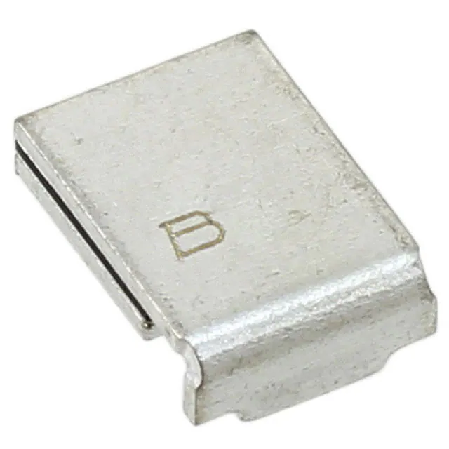
Typical Part Marking
030
-SM
MF 050
-SM
0
MF 75, M
-S
FMF M100 SM0
7
,
MF SM18 MF-S 5/60
-SM 5/3
M1
00/
3
MF 125
33
-SM
MF 150,
MF
-SM
-SM
MF 200
150
-SM
/33
MF 250
-SM
3
MF
0
-SM 0
260
Represents total content. Layout may vary.
PART IDENTIFICATION
030
7A
MF
MF
-SM
MANUFACTURER'S
TRADEMARK
100
Time to Trip (Seconds)
10
1
0.1
0.01
0.001
0.1
1
10
100
Fault Current (Amps)
Specifications are subject to change without notice.
The device characteristics and parameters in this data sheet can and do vary in different applications and actual device performance may vary over time.
Users should verify actual device performance in their specific applications.
DATE CODE WEEK 1 OF 2017 = 7A
(YEAR & WEEK)
WEEK 27 OF 2017 = A7
(WEEK & YEAR)
�
MF-SM Series - PTC Resettable Fuses
Solder Reflow Recommendations
300
Preheating
Soldering
Cooling
• Recommended reflow methods: IR, vapor phase oven, hot air oven.
250
Temperature (ϒC)
Solder reflow
• Devices are not designed to be wave soldered to the bottom side of the
board.
200
• Gluing the devices is not recommended.
150
• Recommended maximum paste thickness is 0.25 mm (.010 inch).
• Devices can be cleaned using standard industry methods and solvents.
100
Note:
• If reflow temperatures exceed the recommended profile, devices may not
meet the performance requirements.
50
0
Rework
160–220
10–20
120
• A device should not be reworked.
Time (seconds)
Storage Recommendations
The recommended long term storage conditions for Multifuse® Polymer PTC devices are 40 °C maximum and 70 % RH maximum. All devices should
remain in the original sealed packaging prior to use. Devices may not conform with data sheet specifications if these storage recommendations are
exceeded. Devices stored in this manner have an indefinite shelf life.
MF-SM SERIES, REV. V, 10/17
Specifications are subject to change without notice.
The device characteristics and parameters in this data sheet can and do vary in different applications and actual device performance may vary over time.
Users should verify actual device performance in their specific applications.
�
MF-SM, MF-SM/33, MF-SM/60 & MF-SM/250 Series Tape and Reel Specifications
NOTE: Effective December 1, 2010 (product date code V0), the cover tape was changed to the new 3M™ Universal Cover Tape (UCT).
Tape Dimensions
W max.
P0
P1
P2
A0
B0
MF-SM030, 050, 075, 100, 125, 260, 300;
MF-SM150, 200, 250;
MF-SM075/60; MF-SM-100/33; MF-SM008/250
MF-SM-150/33, MF-SM-185/33;
per EIA-481-2
MF-SM013/250 per EIA 481-2
16.3 16.3
(0.642) (0.642)
4.0 ± 0.1
4.0 ± 0.1
(0.157 ± 0.004)
(0.157 ± 0.004)
8.0 ± 0.1
12.0 ± 0.1
(0.315 ± 0.004)
(0.472 ± 0.004)
2.0 ± 0.1
2.0 ± 0.1
(0.079 ± 0.004)
(0.079 ± 0.004)
5.7 ± 0.1
6.9 ± 0.1
(0.224 ± 0.004)
(0.272 ± 0.004)
8.1 ± 0.1
9.6 ± 0.1
(0.319 ± 0.004)
(0.378 ± 0.004)
12.1 12.1
(0.476) (0.476)
1.5 + 0.1/-0.0
1.5 + 0.1/-0.0
(0.059 + 0.004/-0)
(0.059 + 0.004/-0)
7.5 ± 0.1
7.5 ± 0.1
(0.295 + 0.004)
(0.295 + 0.004)
1.75 ± 0.1
1.75 ± 0.1
(0.069 ± 0.004)
(0.069 ± 0.004)
14.25 14.25
(0.561) (0.561)
0.6 0.6
(0.024) (0.024)
0.1 0.1
(0.004) (0.004)
3.4 ± 0.1
3.4 ± 0.1*
(0.134 ± 0.004)
(0.134 ± 0.004)*
390 390
(15.35) (15.35)
160 160
(6.30) (6.30)
B1 max.
D0
F
E1
E2 min.
T max.
T1 max.
K0
Leader min.
Trailer min.
Reel Dimensions
A max.
N min.
W1
W2 max.
360 360
(14.17) (14.17)
50 50
(1.97) (1.97)
16.4 + 2.0/ -0.0
16.4 + 2.0/ -0.0
(0.646 + 0.079/-0)
(0.646 + 0.079/-0)
22.4 22.4
(0.882) (0.882)
3.8 ± 0.1
* Model MF-SM013/250 =
(0.150 ± 0.004)
T
MM
DIMENSIONS:
(INCHES)
D0
P2
P0
E1
W2(MEASURED
AT HUB)
COVER
TAPE
F
E2 W
B1
A
N(HUB DIA.)
B0
K0
T1
A0
P1
Specifications are subject to change without notice.
The device characteristics and parameters in this data sheet can and do vary in different applications and actual device performance may vary over time.
Users should verify actual device performance in their specific applications.
W1(MEASURED
AT HUB)
�


 工商网监
湘ICP备2023018690号
工商网监
湘ICP备2023018690号


