T
PL
IA
N
M
CO
*R
oH
S
Features
Applications
■ Available in E6 series
■ Input/output of DC/DC converters
■ Low profile of 3 mm
■ Power supplies for:
• Portable communication equipment
• Camcorders
• LCD TVs
■ High current
LE
AD
FR
EE
■ RoHS compliant*
µH
1.8
2.2
3.0
3.9
4.7
7.5
10
12
15
18
22
27
33
39
47
56
68
82
100
120
150
180
220
270
330
390
470
Q
Tol. % Ref.
±
±
±
±
±
±
±
±
±
±
±
±
±
±
±
±
±
±
±
±
±
±
±
±
±
±
±
20
20
20
20
20
20
20
20
20
20
20
20
20
20
20
20
20
20
20
20
20
20
20
15
15
15
15
10
11
11
10
10
10
18
20
20
20
17
17
17
18
18
15
15
20
23
22
23
20
20
26
26
28
28
Test
Frequency
(MHz)
SRF
Min.
(MHz)
7.96M
7.96M
7.96M
7.96M
7.96M
7.96M
2.52M
2.52M
2.52M
2.52M
2.52M
2.52M
2.52M
2.52M
2.52M
2.52M
2.52M
2.52M
0.796M
0.796M
0.796M
0.796M
0.796M
0.796M
0.796M
0.796M
0.796M
100.0
90.0
70.0
60.0
50.0
32.0
28.0
26.0
25.0
14.0
22.0
19.0
17.0
16.0
14.0
13.0
11.0
11.0
10.0
9.0
8.0
7.0
6.0
4.1
3.6
2.6
2.1
RDC
Max.
(Ω)
0.038
0.045
0.062
0.07
0.078
0.10
0.145
0.185
0.20
0.27
0.30
0.40
0.45
0.56
0.65
0.68
0.80
1.20
1.40
1.52
1.80
2.20
2.20
3.10
3.60
4.60
5.10
I rms
Max.
(A)
I sat
Typ.
(A)
3.00
2.76
2.20
2.10
1.90
1.44
1.24
1.10
1.02
0.90
0.85
0.75
0.70
0.65
0.60
0.52
0.48
0.42
0.40
0.35
0.32
0.28
0.26
0.22
0.20
0.18
0.16
8.00
6.70
5.60
5.20
4.60
3.90
3.30
3.00
2.60
2.50
2.10
1.90
1.70
1.60
1.40
1.30
1.20
1.00
0.95
0.85
0.80
0.75
0.65
0.60
0.55
0.46
0.45
**KFactor
145
122
106
94
84
69
55
51
48
45
41
35
32
29
27
25
22
21
19
17
15
14
12
11
10
9
8
Δ I (peak-to-peak ripple current, A),
determine core loss from Core Loss vs. Flux Density plot.
Core Loss vs. Flux Density
Test Voltage .......................................1 V
.. 250 °C, 10 sec. max.
(In compliance with JEDEC,
J-STD-020C, Table 4-2)
Operating Temperature
................................-40 °C to +125 °C
(Temperature rise included)
Storage Temperature
................................-40 °C to +125 °C
Resistance to Soldering Heat
.......................... 250 °C, 10 sec. max.
Moisture Sensitivity Level .....................1
................. N/A
Materials
Core ....................... Ferrite DR & RI core
Wire ............................Enameled copper
Base .....................................LCP E4008
Terminal ....................................Cu/Ni/Sn
Rated Current
...............Ind. drop of 10 % typ. at Isat
Temperature Rise
.....................40 °C max. at rated Irms
Packaging .................. 1000 pcs. per reel
Product Dimensions
101
101
SRR1003-1R8M
SRR1003-2R2M
SRR1003-3R0M
SRR1003-3R9M
SRR1003-4R7M
SRR1003-7R5M
SRR1003-100M
SRR1003-120M
SRR1003-150M
SRR1003-180M
SRR1003-220M
SRR1003-270M
SRR1003-330M
SRR1003-390M
SRR1003-470M
SRR1003-560M
SRR1003-680M
SRR1003-820M
SRR1003-101M
SRR1003-121M
SRR1003-151M
SRR1003-181M
SRR1003-221M
SRR1003-271Y
SRR1003-331Y
SRR1003-391Y
SRR1003-471Y
Inductance
1 KHz
Ro VE LEA
HS RS D
CO ION FRE
M SA E
PL R
IA E
NT
*
Bourns Part No.
SRR1003 Series - Shielded Power Inductors
10.3 ± 0.2
10.3(.406
± 0.2± .008)
(.406 ± .008)
12.7 ± 0.1
12.7(.500
± 0.1± .004)
(.500 ± .004)
3.0
3.0 (.118) MAX.
MAX.
(.118)
1000
Core Loss (mW)
100
7.6
7.6 (.299)
(.299) TYP.
TYP.
1 MHz
800 KHz
500 KHz
400 KHz
300 KHz
200 KHz
100 KHz
10
1
2.5
2.5 (.098)
(.098) TYP.
TYP.
2.5
2.5 (.098)
(.098) TYP.
TYP.
0.10
Recommended Layout
0.01
10
100
1000
Flux Density Bp-p (gauss)
WARNING Cancer and Reproductive Harm - www.P65Warnings.ca.gov
* RoHS Directive 2002/95/EC Jan. 27, 2003 including annex and RoHS Recast 2011/65/EU June 8, 2011.
Specifications are subject to change without notice. Users should verify actual device performance in their specific
applications. The products described herein and this document are subject to specific legal disclaimers as set forth on
the last page of this document, and at www.bourns.com/docs/legal/disclaimer.pdf
2.8
2.8 (.110)
(.110)
7.3
7.3 (.287)
(.287)
3.0
3.0 (.118)
(.118)
DIMENSIONS:
MM
(INCHES)
�SRR1003 Series - Shielded Power Inductors
Soldering Profile
Schematic
300
Max. of 10 seconds at 250 °C
Max. of 30 seconds > 220 °C
250 °C
250
Temperature (°C)
200
150
120 - 150 seconds
100
Ramp-down
5 °C/second maximum
50
Ramp-up
4 °/second maximum
0
0
50
100
150
200
250
300
Time (seconds)
330
DIA.
(12.99)
2.0 ± 0.5
(.079 ± .020)
30.4
(1.20)
13.0 ± 0.5
(.512 ± .020)
DIA.
21.0 ± 0.8
(.827 ± .031)
50.0
(1.969)
13.0 ± 0.5
DIA.
(.512 ± .020)
26
(1.02)
4
(.157)
END
START
24
(.945)
3.1
(.122)
16.0
(.63)
NO COMPONENT
COMPONENTS
NO COMPONENT
200
(7.874)
9600
(378.2)
400
(15.748)
USER DIRECTION OF FEED
QTY: 1000 PCS. PER REEL
DIMENSIONS:
MM
(INCHES)
REV. 03/18
Specifications are subject to change without notice.
Users should verify actual device performance in their specific applications.
The products described herein and this document are subject to specific disclaimers as set forth on the last page of this document, and at www.bourns.com/legal/disclaimer.pdf.
�Legal Disclaimer Notice
This legal disclaimer applies to purchasers and users of Bourns® products manufactured by or on behalf of Bourns, Inc. and
P[Z�HɉSPH[LZ��JVSSLJ[P]LS`��¸)V\YUZ¹��
Unless otherwise expressly indicated in writing, Bourns® products and data sheets relating thereto are subject to change
^P[OV\[�UV[PJL���
很抱歉,暂时无法提供与“SRR1003-100M”相匹配的价格&库存,您可以联系我们找货
免费人工找货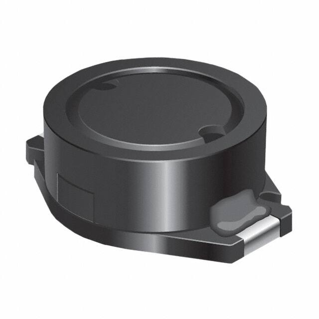


 工商网监
湘ICP备2023018690号
工商网监
湘ICP备2023018690号
