■ Shielded construction
■ Inductance range: 1.0 to 1000 μH
■ Heating current up to 11 A
10
&
*
A E Ro H
C- S C
Q2 O
0 0 MP
QU LI A
AL NT
IF
IE
D
Features
0
■ Dimensions: 12 x 12 x 10 mm
■ AEC-Q200 qualified
■ RoHS compliant* and halogen free**
SRR1210A Series - Shielded Power Inductors
Electrical Specifications @ 25 °C
Bourns
Part Number
SRR1210A-1R0Y
SRR1210A-1R8Y
SRR1210A-2R2Y
SRR1210A-3R3Y
SRR1210A-4R7Y
SRR1210A-5R6Y
SRR1210A-6R8Y
SRR1210A-8R2Y
SRR1210A-100M
SRR1210A-120M
SRR1210A-150M
SRR1210A-180M
SRR1210A-220M
SRR1210A-270M
SRR1210A-330M
SRR1210A-390M
SRR1210A-470M
SRR1210A-560M
SRR1210A-680M
SRR1210A-820M
SRR1210A-101M
SRR1210A-121M
SRR1210A-151M
SRR1210A-181M
SRR1210A-221M
SRR1210A-271M
SRR1210A-331M
SRR1210A-391M
SRR1210A-471M
SRR1210A-561M
SRR1210A-681M
SRR1210A-821M
SRR1210A-102M
Inductance
@ 1 kHz /
0.25 V
L
Tol.
(μH)
(%)
1.0
± 30
1.8
± 30
2.2
± 30
3.3
± 30
4.7
± 30
5.6
± 30
6.8
± 30
8.2
± 30
10
± 20
12
± 20
15
± 20
18
± 20
22
± 20
27
± 20
33
± 20
39
± 20
47
± 20
56
± 20
68
± 20
82
± 20
100
± 20
120
± 20
150
± 20
180
± 20
220
± 20
270
± 20
330
± 20
390
± 20
470
± 20
560
± 20
680
± 20
820
± 20
1000 ± 20
General Specifications
Q Test
Q
Freq.
Ref.
(MHz)
10
10
10
15
8
12
12
11
16
14
16
13
16
16
16
16
16
8
12
15
16
13
12
14
15
16
14
16
12
12
11
6
22
7.96
7.96
7.96
7.96
7.96
7.96
7.96
7.96
2.52
2.52
2.52
2.52
2.52
2.52
2.52
2.52
2.52
2.52
2.52
2.52
0.796
0.796
0.796
0.796
0.796
0.796
0.796
0.796
0.796
0.796
0.796
0.796
0.796
SRF
(MHz)
Typ.
DCR
(Ω)
Max.
I rms
(A)
I sat
(A)
***KFactor
85
56
54
44
35
28
20
16
12
18
10.5
8
8
6.5
6.5
4.5
4.5
4
3.8
3.5
3
2.6
2.2
1.8
1.8
1.8
1.8
1.3
0.85
0.85
0.85
0.85
0.85
0.006
0.075
0.09
0.01
0.012
0.0135
0.015
0.017
0.018
0.022
0.032
0.035
0.038
0.04
0.052
0.066
0.072
0.09
0.102
0.112
0.135
0.17
0.19
0.25
0.315
0.41
0.45
0.6
0.82
0.9
1.2
1.32
1.65
11.0
10.2
9.5
9.0
8.5
8.0
7.85
7.25
6.5
6.3
5.8
5.5
5.2
5.0
4.4
4.2
3.8
3.4
3.0
2.8
2.5
2.3
2.2
1.9
1.7
1.5
1.4
1.3
1.2
1.1
1.0
0.85
0.75
16.5
13.2
12.2
10.5
9.6
8.5
8.3
7.55
6.5
6.1
5.3
5.1
4.5
4.2
3.7
3.5
3.1
2.9
2.7
2.5
2.2
1.9
1.8
1.6
1.5
1.3
1.2
1.1
1.0
0.95
0.85
0.75
0.7
86
67
55
46
40
35
32
29
26
24
21
19
17
15
14
13
12
11
10
9
8
7
7
6
5
5
4
4
4
3
3
3
3
***K-Factor: To calculate core flux density, Bp-p (gauss) = K x L(μH) x Δ I (peak-to-peak ripple current,
A), determine core loss from Core Loss vs. Flux Density plot.
How to Order
Electrical Schematic
Operating Temperature
................................. -40 °C to +125 °C
(Temperature rise included)
Storage Temperature
................................. -40 °C to +125 °C
Temperature Rise
.........................40 °C typ. at rated Irms
Inductance drop .....................20 % at Isat
Materials
Core ............................................... Ferrite
Wire ..............................Enameled copper
Terminal Finish .................................... Sn
Packaging ...................... 250 pcs. per reel
Product Dimensions
12.0 ± 0.5
(.472 ± .020)
1R0
12.0 ± 0.5
(.472 ± .020)
INDUCTANCE
CODE
10.0
MAX.
(.394)
4.9
REF.
(.193)
7.9
REF.
(.311)
Recommended Layout
REF.
5.3
(.209)
REF.
2.8
(.110)
SRR1210A - 100M
Model
7.3
REF.
(.287)
Value Code (see table)
WARNING Cancer and Reproductive Harm www.P65Warnings.ca.gov
* RoHS Directive 2015/863, Mar 31, 2015 and Annex.
** Bourns considers a product to be “halogen free” if (a) the Bromine (Br) content is 900 ppm or less; (b) the Chlorine
(Cl) content is 900 ppm or less; and (c) the total Bromine (Br) and Chlorine (Cl) content is 1500 ppm or less.
Specifications are subject to change without notice. Users should verify actual device performance in their specific
applications. The products described herein and this document are subject to specific legal disclaimers as set forth on the
last page of this document, and at www.bourns.com/docs/legal/disclaimer.pdf.
2.8
(.110)
REF.
DIMENSIONS:
MM
(INCHES)
�SRR1210A Series - Shielded Power Inductors
Inductance vs. IDC
SRR1210A-4R7Y
L @ 25 °C
6.0
SRR1210A-220M
L @ 125 °C
25.0
5.0
L @ 25 °C
L @ 125 °C
20.0
L (µH)
L (µH)
4.0
3.0
2.0
15.0
10.0
5.0
1.0
0.0
0.0
2.0
4.0
6.0
8.0
0.0
0.0
10.0
1.0
2.0
SRR1210A-101M
L @ 25 °C
100.0
4.0
5.0
6.0
SRR1210A-102M
L @ 25 °C
L @ 125 °C
L @ 125 °C
1200
1000
80.0
800
60.0
L (µH)
L (µH)
3.0
IDC (A)
IDC (A)
40.0
600
400
20.0
200
0.0
0.0
0.5
1.0
1.5
2.0
2.5
3.0
0.0
0.0
3.5
0.2
0.4
0.6
0.8
IDC (A)
IDC (A)
SRR1210A-4R7Y
SRR1210A-220M
1.0
Temperature Rise vs. IDC
ΔT @ 25 °C
70.0
70.0
60.0
60.0
50.0
50.0
ΔT (°C)
ΔT (°C)
ΔT @ 25 °C
40.0
30.0
40.0
30.0
20.0
20.0
10.0
10.0
0.0
0.0
2.0
4.0
6.0
8.0
0.0
10.0
0.0
2.0
IDC (A)
SRR1210A-101M
70.0
50.0
60.0
ΔT (°C)
ΔT (°C)
ΔT @ 25 °C
80.0
60.0
40.0
30.0
20.0
50.0
40.0
30.0
20.0
10.0
0.0
6.0
SRR1210A-102M
ΔT @ 25 °C
70.0
4.0
IDC (A)
10.0
0.0 0.5
1.0
1.5
2.0
IDC (A)
2.5
3.0
3.5
0.0
0.0
0.2
0.4
0.6
0.8
1.0
IDC (A)
Specifications are subject to change without notice.
Users should verify actual device performance in their specific applications.
The products described herein and this document are subject to specific legal disclaimers as set forth on the last page of this document, and at www.bourns.com/docs/legal/disclaimer.pdf.
�SRR1210A Series - Shielded Power Inductors
Soldering Profile
Temperature
Rising Area
Preheat Area
+4.0 °C / sec. max.
150~200 °C / 60~120 sec.
Reflow Area
Forced Cooling Area
+3.0 °C / sec. max.
-(1.0~5.0) °C / sec. max.
250
217 °C
Temperature (°C)
Peak Temperature:
245 °C max.
60 ~ 150 sec.
60 sec. max.
200
150
Time Above 245 °C:
30 sec. max.
60 ~ 120 sec.
100
Time Above 217 °C:
60 ~ 150 sec. max.
50
0
50
100
150
200
250
Time (Seconds)
Core Loss vs. Flux Density
10000
Core Loss (mW)
1000
100
10
1
0.1
0.01
10
100
1 MHz
800 KHz
500 KHz
400 KHz
300 KHz
200 KHz
100 KHz
1000
Flux Density Bp-p (gauss)
Specifications are subject to change without notice.
Users should verify actual device performance in their specific applications.
The products described herein and this document are subject to specific legal disclaimers as set forth on the last page of this document, and at www.bourns.com/docs/legal/disclaimer.pdf.
�SRR1210A Series - Shielded Power Inductors
Packaging Specifications
2.0 ± 0.5
(.079 ± .020)
330
DIA.
(12.99)
30.4
(1.197)
THICKNESS
0.10
(.004)
MAX.
13.0
(.512)
DIA.
21.0 ± 0.8
(.827 ± .031)
EMBOSSED
CAVITY
50.0 -0
(1.969 -0)
13.0
DIA.
(.512)
EMBOSSED
CARRIER
26 +0
(1.024 +0)
20.0
(.787)
END
24.0
(.945)
1R0
NO COMPONENT
4.0
(.157)
1R0
1R0
COMPONENTS
START
1R0
NO COMPONENT
400
(15.75)
200
(7.87)
USER DIRECTION OF FEED
QTY: 250 PCS. PER REEL
DIMENSIONS:
MM
(INCHES)
Asia-Pacific: Tel: +886-2 2562-4117 • Email: asiacus@bourns.com
EMEA: Tel: +36 88 885 877 • Email: eurocus@bourns.com
The Americas: Tel: +1-951 781-5500 • Email: americus@bourns.com
www.bourns.com
REV. 11/19
Specifications are subject to change without notice.
Users should verify actual device performance in their specific applications.
The products described herein and this document are subject to specific legal disclaimers as set forth on the last page of this document, and at www.bourns.com/docs/legal/disclaimer.pdf.
�Legal Disclaimer Notice
This legal disclaimer applies to purchasers and users of Bourns® products manufactured by or on behalf of Bourns, Inc. and
P[Z�HɉSPH[LZ��JVSSLJ[P]LS`��¸)V\YUZ¹��
Unless otherwise expressly indicated in writing, Bourns® products and data sheets relating thereto are subject to change
^P[OV\[�UV[PJL���
很抱歉,暂时无法提供与“SRR1210A-470M”相匹配的价格&库存,您可以联系我们找货
免费人工找货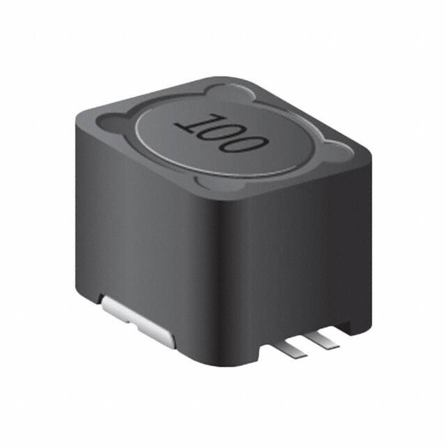


 工商网监
湘ICP备2023018690号
工商网监
湘ICP备2023018690号
