Order
Now
Product
Folder
Support &
Community
Tools &
Software
Technical
Documents
ADS1260, ADS1261
SBAS760C – MARCH 2018 – REVISED JANUARY 2019
ADS126x Precision, 5-channel and 10-channel, 40-kSPS, 24-bit,
delta-sigma ADCs with PGA and monitors
1 Features
3 Description
•
The ADS1260 and ADS1261 (ADS126x) are
precision, 40-kSPS, delta-sigma (ΔΣ) analog-to-digital
converters (ADCs) that include a programmable gain
amplifier (PGA). The devices also include a precision
voltage reference and internal fault monitors. The
sensor-ready ADCs give a high-accuracy, single-chip
solution for the most demanding measurements, for
example, weigh scales and resistance temperature
detectors (RTDs).
1
•
•
•
•
•
•
•
•
•
•
•
•
•
•
•
24-bit, high-precision ADCs
– Offset drift: 1 nV/°C
– Gain drift: 0.5 ppm/°C
– Noise: 30 nVRMS (20 SPS, gain = 128)
– Linearity: 2 ppm
CMOS PGA gain: 1 to 128
Wide input voltage range: ±7 mV to ±5 V
Data rate: 2.5 SPS to 40 kSPS
2.5-V reference: 2 ppm/°C
Simultaneous 50-Hz and 60-Hz rejection mode
Single-cycle settling mode
Signal and reference monitors
5-V or ±2.5-V power supply
Internal temperature sensor
Cyclic redundancy check (CRC)
Excitation current sources
Sensor burn-out current sources
Four general-purpose inputs/outputs (ADS1261)
AC excitation for bridge sensors (ADS1261)
5-mm × 5-mm VQFN package
The ADCs contain an input signal multiplexer, a lownoise PGA (with gains from 1 to 128), a 24-bit ΔΣ
modulator, a precision voltage reference, and a
programmable digital filter.
The high-impedance PGA inputs (1 GΩ) decrease
measurement error due to sensor loading. The
ADS1260 supports three differential or five singleended inputs. The ADS1261 supports five differential
or ten single-ended inputs. The integrated current
sources simplify the measurement of RTDs.
The flexible digital filter is programmable for singlecycle
settled
conversions,
while
supplying
simultaneous 50-Hz and 60-Hz line cycle rejection.
Signal and reference monitors, a temperature sensor,
and CRC data verification make data reliability better.
The ADS126x are pin compatible devices given in a
5-mm × 5-mm VQFN package and are specified
across the –40°C to +125°C temperature range.
2 Applications
•
•
•
•
•
PLC analog input modules
Weigh scales and strain-gauge digitizers
Temperature, pressure measurement
Lab instrumentation
Process analytics
Device Information(1)
PART NUMBER
ADS126x
PACKAGE
VQFN (32)
BODY SIZE (NOM)
5.0 mm × 5.0 mm
(1) For all available packages, see the package option addendum
at the end of the data sheet.
Block Diagram
REFOUT
5 V (A)
2.5-V
Ref
ADS1260
ADS1261
Ref
Mux
3 V ± 5 V (D)
START
AIN0
Sensor
Excitation
AIN1
AIN2
Sensor
Test
AIN3
Control
Ref
Monitor
RESET
PWDN
DRDY
Buf
AIN4
AINCOM
Input
Mux
Level Shift
PGA
AIN5
Digital
Filter
Serial
Interface
and
CRC
Verification
Signal
Monitor
AIN6
AIN7
CS
DIN
DOUT/DRDY
SCLK
Temp
Sensor
AIN8
AIN9
ADS1261
24-Bit
û ADC
Supply
Monitor
GPIO
AC-Exc
(A)
Internal
Oscillator
Clock
Mux
CLKIN
(D)
1
An IMPORTANT NOTICE at the end of this data sheet addresses availability, warranty, changes, use in safety-critical applications,
intellectual property matters and other important disclaimers. PRODUCTION DATA.
�ADS1260, ADS1261
SBAS760C – MARCH 2018 – REVISED JANUARY 2019
www.ti.com
Table of Contents
1
2
3
4
5
6
7
Features ..................................................................
Applications ...........................................................
Description .............................................................
Revision History.....................................................
Device Comparison Table.....................................
Pin Configuration and Functions .........................
Specifications.........................................................
7.1
7.2
7.3
7.4
7.5
7.6
7.7
7.8
1
1
1
2
4
4
6
Absolute Maximum Ratings ...................................... 6
ESD Ratings.............................................................. 6
Recommended Operating Conditions....................... 7
Thermal Information .................................................. 7
Electrical Characteristics........................................... 8
Timing Requirements .............................................. 11
Switching Characteristics ........................................ 12
Typical Characteristics ............................................ 15
8
Parameter Measurement Information ................ 22
9
Detailed Description ............................................ 26
8.1 Noise Performance ................................................. 22
9.1
9.2
9.3
9.4
Overview .................................................................
Functional Block Diagram .......................................
Feature Description.................................................
Device Functional Modes........................................
26
27
28
43
9.5 Programming........................................................... 50
9.6 Register Map........................................................... 59
10 Application and Implementation........................ 72
10.1 Application Information.......................................... 72
10.2 Typical Application ................................................ 76
10.3 Initialization Setup ................................................. 79
11 Power Supply Recommendations ..................... 80
11.1 Power-Supply Decoupling..................................... 80
11.2 Analog Power-Supply Clamp ................................ 80
11.3 Power-Supply Sequencing.................................... 80
12 Layout................................................................... 81
12.1 Layout Guidelines ................................................. 81
12.2 Layout Example .................................................... 81
13 Device and Documentation Support ................. 83
13.1
13.2
13.3
13.4
13.5
13.6
13.7
Documentation Support ........................................
Related Links ........................................................
Receiving Notification of Documentation Updates
Community Resources..........................................
Trademarks ...........................................................
Electrostatic Discharge Caution ............................
Glossary ................................................................
83
83
83
83
83
83
83
14 Mechanical, Packaging, and Orderable
Information ........................................................... 83
4 Revision History
Changes from Revision B (October 2018) to Revision C
Page
•
Changed Figure 14, Offset Voltage Long-Term Drift to include 2000-hour data ................................................................ 15
•
Changed Figure 31, Voltage Reference Long-Term Drift to include 2000-hour data ......................................................... 17
•
Changed CRC polynomial to correct listing error: changed CRC-8-ATM (HEC): X8 + X2 + X0 + 1 to CRC-8-ATM
(HEC): X8 + X2 + X1 + 1 ........................................................................................................................................................ 52
Changes from Revision A (May 2018) to Revision B
Page
•
Added ADS1261 device to data sheet ................................................................................................................................... 1
•
Changed ADS1260 device from preview to production data (active)..................................................................................... 1
•
Added connection options to NC pins .................................................................................................................................... 5
•
Added differential input current specification for gain = 128 in Electrical Characteristics ..................................................... 8
•
Added no missing codes specification in Electrical Characteristics ...................................................................................... 8
•
Changed integral nonlinearity specification for gain 64 and 128 in Electrical Characteristics ............................................... 8
•
Changed integral nonlinearity specification for 40 kSPS mode in Electrical Characteristics ................................................ 8
•
Added offset voltage long-term drift in Electrical Characteristics .......................................................................................... 8
•
Added note for PSRR calculation in Electrical Characteristics ............................................................................................. 8
•
Changed voltage reference inputs specification in Electrical Characteristics based on updated characteristics .................. 9
•
Added voltage reference initial error specification for ADS1260B and ADS1261B in Electrical Characteristics .................. 9
•
Added voltage reference temperature drift specification for ADS1260B and ADS1261B in Electrical Characteristics ........ 9
•
Added voltage reference long-term drift in Electrical Characteristics .................................................................................... 9
•
Added voltage reference thermal hysteresis in Electrical Characteristics ............................................................................. 9
•
Changed th(SCDO2) specification in Switching Characteristics ............................................................................................... 12
2
Submit Documentation Feedback
Copyright © 2018–2019, Texas Instruments Incorporated
Product Folder Links: ADS1260 ADS1261
�ADS1260, ADS1261
www.ti.com
SBAS760C – MARCH 2018 – REVISED JANUARY 2019
•
Changed tp(SCDO2) specification in Switching Characteristics................................................................................................ 12
•
Added Figure 14, Offset Voltage Long-Term Drift................................................................................................................ 15
•
Changed Figure 24, Conversion Data Histogram (gain = 4) to 8192 data points ................................................................ 16
•
Changed Figure 25, Conversion Data Histogram (gain = 128) to 8192 data points ........................................................... 16
•
Changed Figure 27, Integral Nonlinearity vs Temperature based on updated characteristics ........................................... 17
•
Changed Figure 28, Integral Nonlinearity Distribution to add gain = 128 ........................................................................... 17
•
Changed Figure 29, Integral Nonlinearity vs Reference Voltage to add gain = 64 and 128 ............................................... 17
•
Added Figure 30, Voltage Reference vs Temperature for ADS1260B, ADS1261B ............................................................ 17
•
Added Figure 31, Voltage Reference Long-Term Drift......................................................................................................... 17
•
Changed Figure 32, Reference Input Current vs Reference Voltage based on updated characteristics ............................ 17
•
Added Figure 39, CMRR vs Frequency .............................................................................................................................. 19
•
Added Figure 40, PSRR vs Frequency ............................................................................................................................... 19
•
Added text for Table 2, Effective Resolution (Noise-Free Resolution)................................................................................. 22
•
Changed Table 2, Effective Resolution (Noise-Free Resolution) based on updated characteristics................................... 24
Changes from Original (March 2018) to Revision A
•
Page
Changed ADS1261 device from advanced information to production data (active)............................................................... 1
Copyright © 2018–2019, Texas Instruments Incorporated
Product Folder Links: ADS1260 ADS1261
Submit Documentation Feedback
3
�ADS1260, ADS1261
SBAS760C – MARCH 2018 – REVISED JANUARY 2019
www.ti.com
5 Device Comparison Table
CHANNELS (1)
PART
NUMBER
SINGLE-ENDED
DIFFERENTIAL
ADS1260B (2)
5
ADS1261B
ADS1261
(1)
(2)
VOLTAGE REFERENCE GRADE
REFERENCE INPUTS
GPIO
AC EXCITATION
3
12 ppm/°C max
1
—
10
5
12 ppm/°C max
2
4
10
5
40 ppm/°C max
2
4
Reference inputs, GPIOs, and AC-excitation outputs are multiplexed with the analog input channels.
The ADS1260 is available in B grade only.
6 Pin Configuration and Functions
RHB Package: ADS1260
VQFN-32
Top View
AIN3
AIN4
AIN5
AIN6
AIN7
28
27
26
25
NC
25
29
NC
26
AIN2
NC
27
30
AIN4
28
AIN1
AIN3
29
31
AIN2
30
AIN0
AIN1
31
32
AIN0
32
RHB Package: ADS1261
VQFN-32
Top View
AINCOM
1
24
NC
AINCOM
1
24
AIN8
CAPP
2
23
NC
CAPP
2
23
AIN9
CAPN
3
22
NC
CAPN
3
22
NC
AVDD
4
21
NC
AVDD
4
21
NC
AVSS
5
20
NC
AVSS
5
20
NC
REFOUT
6
19
NC
REFOUT
6
19
NC
PWDN
7
18
CLKIN
PWDN
7
18
CLKIN
RESET
8
17
DVDD
RESET
8
17
DVDD
4
12
13
14
15
16
DIN
DRDY
DOUT/DRDY
BYPASS
DGND
16
DGND
11
15
BYPASS
SCLK
14
DOUT/DRDY
10
13
DRDY
Not to scale
CS
12
DIN
9
11
SCLK
Submit Documentation Feedback
Thermal Pad
START
10
CS
START
9
Thermal Pad
Not to scale
Copyright © 2018–2019, Texas Instruments Incorporated
Product Folder Links: ADS1260 ADS1261
�ADS1260, ADS1261
www.ti.com
SBAS760C – MARCH 2018 – REVISED JANUARY 2019
Pin Functions
PIN
NO.
TYPE
DESCRIPTION
ADS1260
ADS1261
1
AINCOM
AINCOM
Analog
input/output
2
CAPP
CAPP
Analog
output
PGA output P; connect a 4.7-nF C0G dielectric capacitor across CAPP and
CAPN
3
CAPN
CAPN
Analog
output
PGA output N; connect a 4.7-nF C0G dielectric capacitor across CAPP and
CAPN
4
AVDD
AVDD
Analog
Positive analog power supply
5
AVSS
AVSS
Analog
Negative analog power supply
REFOUT
Analog
output
Internal 2.5-V reference output; connect a 10-µF capacitor to AVSS
6
REFOUT
Analog input common, IDAC1, IDAC2, VBIAS
7
PWDN
PWDN
Digital input
Power down, active low
8
RESET
RESET
Digital input
Reset, active low
9
START
START
Digital input
Start conversion control, active high
10
CS
CS
Digital input
Serial interface chip select, active low
11
SCLK
SCLK
Digital Input
Serial interface shift clock
12
DIN
DIN
Digital Input
Serial interface data input
DRDY
DRDY
13
14
DOUT/DRDY DOUT/DRDY
Digital output Data ready indicator, active low
Digital output Dual function serial interface data output and active-low data ready indicator
15
BYPASS
BYPASS
Analog
output
Internal subregulator bypass; connect a 1-µF capacitor to DGND
16
DGND
DGND
Digital
Digital ground
17
DVDD
DVDD
Digital
Digital power supply
18
CLKIN
CLKIN
Digital input
NC
NC
—
ADS1260: No connection. Electrically float or connect to DGND
ADS1261: Analog input 9, IDAC1, IDAC2
19-22
1) Internal oscillator: connect to DGND
2) External clock: connect clock input
No connection. Electrically float or connect to DGND
23
NC
AIN9
Analog
input/output
24
NC
AIN8
Analog
input/output
ADS1260: No connection. Electrically float or connect to DGND
ADS1261: Analog input 8, IDAC1, IDAC2
25
NC
AIN7
Analog
input/output
ADS1260: No connection. Electrically float or connect to DGND
ADS1261: Analog input 7, IDAC1, IDAC2
26
NC
AIN6
Analog
input/output
ADS1260: No connection. Electrically float or connect to DGND
ADS1261: Analog input 6, IDAC1, IDAC2
27
NC
AIN5
Analog
input/output
ADS1260: No connection. Electrically float or connect to DGND
ADS1261: Analog input 5, IDAC1, IDAC2, GPIO3, ACX2
28
AIN4
AIN4
Analog
input/output
ADS1260: Analog input 4, IDAC1, IDAC2
ADS1261: Analog input 4, IDAC1, IDAC2, GPIO2, ACX1
29
AIN3
AIN3
Analog
input/output
ADS1260: Analog input 3, IDAC1, IDAC2
ADS1261: Analog input 3, IDAC1, IDAC2, REFN1, GPIO1, ACX2
30
AIN2
AIN2
Analog
input/output
ADS1260: Analog input 2, IDAC1, IDAC2
ADS1261: Analog input 2, IDAC1, IDAC2, REFP1, GPIO0, ACX1
31
AIN1
AIN1
Analog
input/output
Analog input 1, IDAC1, IDAC2, REFN0
32
AIN0
AIN0
Analog
input/output
Analog input 0, IDAC1, IDAC2, REFP0
Thermal Pad
Pad
Pad
—
Exposed thermal pad; Connect to AVSS. Pad must be soldered for
mechanical integrity.
Copyright © 2018–2019, Texas Instruments Incorporated
Product Folder Links: ADS1260 ADS1261
Submit Documentation Feedback
5
�ADS1260, ADS1261
SBAS760C – MARCH 2018 – REVISED JANUARY 2019
www.ti.com
7 Specifications
7.1 Absolute Maximum Ratings
see
(1)
MIN
MAX
–0.3
7
AVSS to DGND
–3
0.3
DVDD to DGND
–0.3
7
AVDD + 0.3
AVDD to AVSS
Power-supply voltage
Analog input voltage
AINx
AVSS – 0.3
Digital input voltage
CS, SCLK, DIN, DOUT/DRDY, DRDY, START, RESET, PWDN, CLKIN
DGND – 0.3 DVDD + 0.3
Input current
Continuous, all pins except power-supply pins (2)
Temperature
(1)
(2)
–10
Junction, TJ
Storage, Tstg
–60
UNIT
V
V
V
10
mA
150
°C
150
°C
Stresses beyond those listed under Absolute Maximum Ratings may cause permanent damage to the device. These are stress ratings
only, which do not imply functional operation of the device at these or any other conditions beyond those indicated under Recommended
Operating Conditions. Exposure to absolute-maximum-rated conditions for extended periods may affect device reliability.
Input and output pins are diode-clamped to the internal power supplies. Limit the input current to 10 mA in the event the analog input
voltage exceeds AVDD + 0.3 V or AVSS – 0.3 V, or if the digital input voltage exceeds DVDD + 0.3 V or DGND – 0.3 V.
7.2 ESD Ratings
VALUE
V(ESD)
(1)
(2)
6
Electrostatic discharge
Human-body model (HBM), per ANSI/ESDA/JEDEC JS-001 (1)
±2000
Charged-device model (CDM), per JEDEC specification JESD22-C101 (2)
±500
UNIT
V
JEDEC document JEP155 states that 500-V HBM allows safe manufacturing with a standard ESD control process.
JEDEC document JEP157 states that 250-V CDM allows safe manufacturing with a standard ESD control process.
Submit Documentation Feedback
Copyright © 2018–2019, Texas Instruments Incorporated
Product Folder Links: ADS1260 ADS1261
�ADS1260, ADS1261
www.ti.com
SBAS760C – MARCH 2018 – REVISED JANUARY 2019
7.3 Recommended Operating Conditions
MIN
NOM
MAX
AVDD to AVSS
4.75
5
5.25
AVSS to DGND
–2.6
0
DVDD to DGND
2.7
5.25
UNIT
POWER SUPPLY
Analog power supply
Digital power supply
V
V
ANALOG INPUTS
V(AINx)
Absolute input voltage
VIN
Differential input voltage
PGA mode
PGA bypassed
See Equation 5
AVSS – 0.1
VIN = VAINp – VAINn
V
AVDD + 0.1
±VREF / Gain
See
(1)
V
VOLTAGE REFERENCE INPUTS
VREF
Differential reference voltage
0.9
AVDD – AVSS
V
V(REFNx)
Negative reference voltage
VREF = V(REFPx) – V(REFNx)
AVSS – 0.05
V(REFPx) – 0.9
V
V(REFPx)
Positive reference voltage
V(REFNx) + 0.9
AVDD + 0.05
V
EXTERNAL CLOCK
fCLK
Frequency
2.5 SPS to 25.6 kSPS
1
7.3728
8
40 kSPS
1
10.24
10.75
Duty cycle
MHz
40%
60%
AVSS
AVDD
V
DGND
DVDD
V
–45
125
°C
GENERAL-PURPOSE INPUTS/OUTPUTS (GPIOs)
Input voltage
DIGITAL INPUTS (Other Than GPIOs)
Input voltage
TEMPERATURE
TA
(1)
Operating ambient temperature
In PGA mode, the maximum differential input voltage is ±(AVDD – AVSS – 0.6 V) / Gain, when operating with
VREF ≥ AVDD – AVSS – 0.6 V.
7.4 Thermal Information
ADS126x
THERMAL METRIC (1)
RHB (VQFN)
UNIT
32 PINS
RθJA
Junction-to-ambient thermal resistance
28.6
°C/W
RθJC(top)
Junction-to-case (top) thermal resistance
17.0
°C/W
RθJB
Junction-to-board thermal resistance
9.7
°C/W
ψJT
Junction-to-top characterization parameter
0.2
°C/W
ψJB
Junction-to-board characterization parameter
9.7
°C/W
RθJC(bot)
Junction-to-case (bottom) thermal resistance
0.7
°C/W
(1)
For more information about traditional and new thermal metrics, see the Semiconductor and IC Package Thermal Metrics application
report.
Copyright © 2018–2019, Texas Instruments Incorporated
Product Folder Links: ADS1260 ADS1261
Submit Documentation Feedback
7
�ADS1260, ADS1261
SBAS760C – MARCH 2018 – REVISED JANUARY 2019
www.ti.com
7.5 Electrical Characteristics
minimum and maximum specifications apply from TA = –40°C to +125°C; typical specifications are at TA = 25°C; all
specifications are at AVDD = 5 V, AVSS = 0 V, DVDD = 3.3 V, VREF = 2.5 V, fCLK = 7.3728 MHz, PGA mode, gain = 1, and
data rate = 20 SPS (unless otherwise noted)
PARAMETER
TEST CONDITIONS
MIN
TYP
MAX
4
6
UNIT
ANALOG INPUTS
Absolute input current
PGA mode, V(AINx) = 2.5 V
PGA bypass
200
Absolute input current drift
0.01
PGA mode, VIN = 19 mV
Differential input current
nA/°C
±0.1
PGA mode, VIN = 2.5 V
–3
PGA mode, chop mode (1)
±1
3
±5
PGA bypass, VIN = 2.5 V
nA
±40
Differential input current drift
Differential input impedance
nA
0.05
PGA mode
PGA bypass
Crosstalk
nA/°C
1
GΩ
50
MΩ
0.1
µV/V
PGA
Gain settings
Antialias filter frequency
1, 2, 4, 8, 16, 32, 64, 128
CCAPP,
CAPN = 4.7 nF
V/V
60
kHz
PERFORMANCE
Resolution
DR
No missing codes
24
Data rate
Noise performance
INL
Integral nonlinearity
Offset voltage
±2
10
Gain = 32 to 128
–12
±3
12
Gain = 1 to 32 (40 kSPS)
–15
±5
15
–175 / gain – 5
±50 / gain
175 / gain + 5
–0.5 / gain –
0.05
±0.2 / gain
0.5 / gain +
0.05
TA = 25°C, chop mode
Gain = 16 to 128
Chop mode, gain = 1 to 128
GE
Gain error
Gain drift
NMRR
Normal-mode rejection ratio (2)
CMRR
Common-mode rejection ratio (3)
PSRR
Power-supply rejection ratio (4)
Gain = 1, 1000 hr
TA = 25°C, gain = 1 to 128
ppmFSR
µV
On the level of noise
Gain = 1 to 8
Offset voltage long-term drift
SPS
See Table 1
–10
After calibration
Offset voltage drift
40000
Gain = 1 to 16
TA = 25°C
VOS
Bits
2.5
100 / gain
350 / gain
10
50
1
5
±0.1
–0.5%
After calibration
±0.05%
nV/°C
µV
0.5%
On the level of noise
Gain = 1 to 128
0.5
4
ppm/°C
See Table 7
Data rate = 20 SPS
130
Data rate = 400 SPS
AVDD and AVSS
DVDD
105
115
85
100
100
120
dB
dB
INTERNAL OSCILLATOR
fCLK
Frequency
2.5 SPS to 25.6 kSPS
7.3728
40 kSPS
Accuracy
(1)
(2)
(3)
(4)
8
MHz
10.24
–2%
±0.5%
2%
Chop-mode input current scales with data rate.
Normal-mode rejection ratio performance depends on the digital filter configuration.
Common-mode rejection ratio is specified at 60 Hz.
Power-supply rejection ratio specified at dc. PSRR (dB) = 20 Log (Δ power supply voltage / Δ offset voltage).
Submit Documentation Feedback
Copyright © 2018–2019, Texas Instruments Incorporated
Product Folder Links: ADS1260 ADS1261
�ADS1260, ADS1261
www.ti.com
SBAS760C – MARCH 2018 – REVISED JANUARY 2019
Electrical Characteristics (continued)
minimum and maximum specifications apply from TA = –40°C to +125°C; typical specifications are at TA = 25°C; all
specifications are at AVDD = 5 V, AVSS = 0 V, DVDD = 3.3 V, VREF = 2.5 V, fCLK = 7.3728 MHz, PGA mode, gain = 1, and
data rate = 20 SPS (unless otherwise noted)
PARAMETER
TEST CONDITIONS
MIN
TYP
MAX
UNIT
VOLTAGE REFERENCE INPUTS
Absolute input current
±250
Input current vs voltage
Input current drift
Input impedance
Differential
nA
15
nA/V
0.2
nA/°C
30
MΩ
INTERNAL VOLTAGE REFERENCE (5)
Voltage
Initial error
Temperature drift
2.5
TA = 25°C, ADS1260B, ADS1261B
±0.1%
TA = 25°C, ADS1261
±0.2%
TA = 0°C to +85°C, ADS1260B,
ADS1261B
2
9
TA = –40°C to +125°C, ADS1260B,
ADS1261B
4
12
10
40
TA = –40°C to +125°C, ADS1261
Long-term drift
Thermal hysteresis (6)
1000 hr
±25
First temperature cycle
±70
Second temperature cycle
±20
Output current
Settling time to ±0.001% of final value
ppm/°C
ppm
ppm
–10
Load regulation
Start-up time
V
±0.2%
10
mA
50
µV/mA
100
ms
EXCITATION CURRENT SOURCES (IDACS)
50, 100, 250, 500, 750,
1000, 1500, 2000, 2500, 3000
Current settings
Compliance range
AVSS
Accuracy
Match error
Temperature drift
Same current magnitudes
µA
AVDD – 1.1
–4%
±0.7%
4%
–1%
±0.1%
1%
Different current magnitudes
V
±1%
Absolute
50
Match drift, IIDAC1 = IIDAC2
5
25
ppm/°C
LEVEL-SHIFT VOLTAGE (VBIAS)
Voltage
(AVDD + AVSS) / 2
V
100
Ω
Output impedance
BURN-OUT CURRENT SOURCES
Current settings
Sink and source
Accuracy
0.05-µA range
0.05, 0.2, 1, 10
0.025
0.05
µA
0.075
µA
TEMPERATURE SENSOR
Sensor voltage
TA = 25°C
Temperature coefficient
122.4
mV
420
µV/°C
MONITORS
PGA output
Reference voltage
(5)
(6)
Low
AVSS + 0.2
High
AVDD – 0.2
Low
0.4
V
0.6
V
Soldered to PCB using recommended PCB layout pattern and using reflow profile per JEDEC standard J-STD-020D.1
Voltage reference hysteresis measured by operating the device at 25°C cycling the device to 0°C and 105°C and returning the device to
25°C.
Copyright © 2018–2019, Texas Instruments Incorporated
Product Folder Links: ADS1260 ADS1261
Submit Documentation Feedback
9
�ADS1260, ADS1261
SBAS760C – MARCH 2018 – REVISED JANUARY 2019
www.ti.com
Electrical Characteristics (continued)
minimum and maximum specifications apply from TA = –40°C to +125°C; typical specifications are at TA = 25°C; all
specifications are at AVDD = 5 V, AVSS = 0 V, DVDD = 3.3 V, VREF = 2.5 V, fCLK = 7.3728 MHz, PGA mode, gain = 1, and
data rate = 20 SPS (unless otherwise noted)
PARAMETER
TEST CONDITIONS
MIN
TYP
MAX
UNIT
GENERAL-PURPOSE INPUTS/OUTPUTS (GPIOs) (7)
VOL
Low-level output voltage
IOL = –1 mA
VOH
High-level output voltage
IOH = 1 mA
VIL
Low-level input voltage
VIH
High-level input voltage
0.2 · AVDD
0.8 · AVDD
V
0.3 · AVDD
0.7 · AVDD
Input hysteresis
V
V
V
0.5
V
DIGITAL INPUTS/OUTPUTS (Other Than GPIOs)
VOL
Low-level output voltage
VOH
High-level output voltage
VIL
Low-level input voltage
VIH
High-level input voltage
IOL = –1 mA
0.2 · DVDD
IOL = –8 mA
IOH = 1 mA
0.2 · DVDD
0.8 · DVDD
IOH = 8 mA
Input leakage
V
0.75 · DVDD
0.3 · DVDD
0.7 · DVDD
Input hysteresis
V
V
0.1
VIH or VIL
V
–10
V
10
µA
POWER SUPPLY
IAVDD,
IAVSS
Analog supply current
PGA bypass
2.7
4.5
PGA mode, gain = 1 to 32
3.8
6
PGA mode, gain = 64 or 128
4.3
6.5
2
8
Power-down mode
IAVDD,
IAVSS
Analog supply current (by function)
Voltage reference
0.2
40-kSPS mode
0.5
Current sources
IDVDD
PD
Digital supply current
Power dissipation
(7)
(8)
GPIO voltage with respect to AVSS.
CLKIN input stopped.
10
Submit Documentation Feedback
mA
µA
mA
As programmed
20 SPS
0.4
0.65
40 kSPS
0.6
0.85
Power-down mode (8)
30
50
PGA mode
20
32
Power-down mode
0.1
0.2
mA
µA
mW
Copyright © 2018–2019, Texas Instruments Incorporated
Product Folder Links: ADS1260 ADS1261
�ADS1260, ADS1261
www.ti.com
SBAS760C – MARCH 2018 – REVISED JANUARY 2019
7.6 Timing Requirements
over operating ambient temperature range, DVDD = 2.7 V to 5.25 V, and DOUT/DRDY load: 20 pF || 100 kΩ to DGND
(unless otherwise noted); see Figure 8
MIN
MAX
UNIT
SERIAL INTERFACE
td(CSSC)
Delay time, first SCLK rising edge after CS falling edge (1)
50
ns
tsu(DI)
Setup time, DIN valid before SCLK falling edge
25
ns
th(DI)
Hold time, DIN valid after SCLK falling edge
25
tc(SC)
SCLK period (2)
97
tw(SCH),
tw(SCL)
Pulse duration, SCLK high or low
40
ns
td(SCCS)
Delay time, last SCLK falling edge before CS rising edge
50
ns
tw(CSH)
Pulse duration, CS high to reset interface
25
td(SCIR)
Delay time, SCLK high or low to force interface auto-reset
ns
106
ns
ns
65540
1/fCLK
RESET
tw(RSTL)
Pulse duration, RESET low
4
1/fCLK
CONVERSION CONTROL
tw(STH)
Pulse duration, START high
4
1/fCLK
tw(STL)
Pulse duration, START low
4
1/fCLK
tsu(DRST)
Setup time, START low or STOP command after DRDY low to stop next
conversion (continuous mode)
th(DRSP)
Hold time, START low or STOP command after DRDY low to continue next
conversion (continuous mode)
(1)
(2)
.
100
150
1/fCLK
1/fCLK
CS can be tied low.
Serial interface time-out mode: minimum SCLK frequency = 1 kHz. Otherwise, no minimum SCLK frequency.
Copyright © 2018–2019, Texas Instruments Incorporated
Product Folder Links: ADS1260 ADS1261
Submit Documentation Feedback
11
�ADS1260, ADS1261
SBAS760C – MARCH 2018 – REVISED JANUARY 2019
www.ti.com
7.7 Switching Characteristics
over operating ambient temperature range, DVDD = 2.7 V to 5.25 V, and DOUT/DRDY load: 20 pF || 100 kΩ to DGND
(unless otherwise noted); see Figure 8
PARAMETER
MIN
TYP
MAX
UNIT
tw(DRH)
Pulse duration, DRDY high
16
tp(CSDO)
Propagation delay time, CS falling edge to DOUT/DRDY
driven
tp(SCDO1)
Propagation delay time, SCLK rising edge to valid
DOUT/DRDY
th(SCDO1)
Hold time, SCLK rising edge to invalid data on
DOUT/DRDY
th(SCDO2)
Hold time, last SCLK falling edge of operation to invalid
data on DOUT/DRDY
tp(SCDO2)
Propagation delay time, last SCLK falling edge to valid
data ready function on DOUT/DRDY
110
ns
tp(CSDOZ)
Propagation delay time, CS rising edge to DOUT/DRDY
high impedance
50
ns
SERIAL INTERFACE
1/fCLK
0
50
ns
40
ns
0
ns
15
ns
RESET
tp(RSCN)
Propagation delay time, RESET rising edge or RESET
command to start of conversion
tp(PRCM)
Propagation delay time, power-on threshold voltage to
ADC communication
tp(CMCN)
Propagation delay time, ADC communication to
conversion start
512
1/fCLK
216
1/fCLK
512
1/fCLK
AC EXCITATION
td(ACX)
Delay time, phase-to-phase blanking period
tc(ACX)
ACX period
8
1/fCLK
2
tSTDR
CONVERSION CONTROL
tp(STDR)
Propagation delay time, START high or START command
to DRDY high
2
1/fCLK
tw(CSH)
CS
td(CSSC)
tc(SC)
td(SCCS)
tw(SCH)
SCLK
th(DI)
tsu(DI)
tw(SCL)
DIN
Figure 1. Serial Interface Timing Requirements
12
Submit Documentation Feedback
Copyright © 2018–2019, Texas Instruments Incorporated
Product Folder Links: ADS1260 ADS1261
�ADS1260, ADS1261
www.ti.com
SBAS760C – MARCH 2018 – REVISED JANUARY 2019
tw(DRH)
DRDY
CS
SCLK
tp(SCDO2)
tp(SCDO1)
tp(CSDO)
DRDY
DOUT/DRDY
(1)
tp(CSDOZ)
(1)
(1)
DATA
DRDY
th(SCDO1)
th(SCDO2)
Before the first SCLK rising edge and after the last SCLK falling edge of a command, the function of DOUT/DRDY is data ready.
Figure 2. Serial Interface Switching Characteristics
Serial Interface
Auto-Reset
td(SCIR)
Next byte transaction
b7
SCLK
b6
b5
b4
b3
b2
b1
b0
Figure 3. Serial Interface Auto-Reset Characteristics
tw(STH)
START
tw(STL)
Serial
Command
START
STOP
tp(STDR)
STOP
tsu(DRST)
DRDY
th(DRSP)
Figure 4. Conversion Control Timing Requirements
Copyright © 2018–2019, Texas Instruments Incorporated
Product Folder Links: ADS1260 ADS1261
Submit Documentation Feedback
13
�ADS1260, ADS1261
SBAS760C – MARCH 2018 – REVISED JANUARY 2019
www.ti.com
DVDD
1 V (typ)
VBYPASS
1 V (typ)
AVDD - AVSS
3.5 V (typ)
All supplies reach thresholds
DRDY
DOUT/DRDY
Begin ADC Communication
tp(PRCM)
tp(CMCN)
Conversion
Status
Start of 1st Conversion
Figure 5. Power-Up Characteristics
tw(RSTL)
RESET
Reset
Command
tp(RSCN)
Conversion
Status
Reset
Start
Figure 6. RESET pin and RESET Command Timing Requirements
tc(ACX)
td(ACX)
td(ACX)
ACX1
ACX1
ACX2
ACX2
Figure 7. AC-Excitation Timing Characteristics
DVDD
½ DVDD
50%
DGND
td, th, tp, tw,tc
Figure 8. Timing Voltage-Level Reference
14
Submit Documentation Feedback
Copyright © 2018–2019, Texas Instruments Incorporated
Product Folder Links: ADS1260 ADS1261
�ADS1260, ADS1261
www.ti.com
SBAS760C – MARCH 2018 – REVISED JANUARY 2019
7.8 Typical Characteristics
at TA = 25°C, AVDD = 5 V, AVSS = 0 V, DVDD = 3.3 V, VREF = 2.5 V, data rate = 20 SPS, fCLK = 7.3728 MHz (fCLK =
10.24 MHz for data rate = 40 kSPS), and gain = 1 (unless otherwise noted)
10
0.5
PGA Bypass
Gain = 1
Gain = 2
8
Gain = 32
Gain = 64
Gain = 128
PGA Bypass
Gain = 1
Gain = 2
0.4
0.3
Offset Voltage (PV)
4
2
0
-2
-4
-6
-8
0.1
0
-0.1
-0.2
-0.4
-20
0
20
40
60
Temperature (qC)
80
100
-0.5
-40
120
-20
0
20
40
60
Temperature (qC)
D009
After calibration, shorted input
80
100
120
D010
Chop mode, after calibration, shorted input
Figure 9. Offset Voltage vs Temperature
Figure 10. Offset Voltage vs Temperature
100
100
Gain = 1
Gain = 16
Gain = 128
90
80
Gain = 1
Gain = 16
Gain = 128
90
80
70
50
Input-Referred Offset Drift (nV/qC)
3.6
3
3.3
2.7
2.4
2.1
0
240
220
200
180
160
140
120
100
80
60
0
40
10
0
20
20
10
0
30
20
1.8
40
30
1.5
40
1.2
50
60
0.9
60
0.6
Population (%)
70
Population (%)
Gain = 32
Gain = 64
Gain = 128
-0.3
-10
-40
Input-Referred Offset Drift (nV/qC)
D012
Shorted input, 30 units
D011
Chop mode, shorted input, 30 units
Figure 11. Offset Voltage Drift Distribution
Figure 12. Offset Voltage Drift Distribution
2
40
30
25
20
Offset Voltage Long-Term Drift (PV)
Gain = 1, 400 SPS
Gain = 1, 40000 SPS
Gain = 16, 400 SPS
Gain = 16, 40000 SPS
Gain = 128, 400 SPS
Gain = 128, 40000
35
Offset Voltage (PV)
Gain = 4
Gain = 8
Gain = 16
0.2
0.3
Offset Voltage (PV)
6
Gain = 4
Gain = 8
Gain = 16
15
10
5
0
-5
-10
0.5
1.5
1
0.5
0
-0.5
-1
-1.5
-2
1
1.5
2
2.5
3
V REF (V)
3.5
4
4.5
5
0
250
D001
After calibration
500
750
1000 1250
Time (hr)
1500
1750
2000
D205
After calibration, gain = 1
Figure 13. Offset Voltage vs Reference Voltage
Figure 14. Offset Voltage Long-Term Drift
Copyright © 2018–2019, Texas Instruments Incorporated
Product Folder Links: ADS1260 ADS1261
Submit Documentation Feedback
15
�ADS1260, ADS1261
SBAS760C – MARCH 2018 – REVISED JANUARY 2019
www.ti.com
Typical Characteristics (continued)
at TA = 25°C, AVDD = 5 V, AVSS = 0 V, DVDD = 3.3 V, VREF = 2.5 V, data rate = 20 SPS, fCLK = 7.3728 MHz (fCLK =
10.24 MHz for data rate = 40 kSPS), and gain = 1 (unless otherwise noted)
50
200
PGA Bypass
Gain = 1
Gain = 2
Gain = 32
Gain = 64
Gain = 128
100
50
0
30
20
10
-50
0.45
Input-Referred Noise (PVRMS )
Gain Error (ppm)
40
30
20
10
0
-10
-20
-30
0.4
Gain = 1
Gain = 2
Gain = 4
Gain = 8
2.4
2.2
2
Gain = 16
Gain = 32
Gain = 64
Gain = 128
0.35
0.3
0.25
0.2
0.15
0.1
0.05
1
1.5
2
2.5
3
VREF (V)
3.5
4
4.5
0
-40
5
-20
0
D002
After calibration
20
40
60
Temperature (qC)
80
100
120
D003
Exce
20 SPS, Sinc4
Figure 17. Gain Error vs Reference Voltage
Figure 18. Noise vs Temperature
10
50
Gain = 1
Gain = 2
Gain = 4
Gain = 8
Gain = 16
Gain = 32
Gain = 64
Gain = 128
45
Input-Referred Noise (PVRMS )
Input-Referred Noise (PVRMS )
1.8
0.5
Gain = 1, 400 SPS
Gain = 1, 40000 SPS
Gain = 128, 400 SPS
Gain = 128, 40000 SPS
50
7
6
5
4
3
2
40
30
25
20
15
10
5
0
-40
0
-40
0
20
40
60
Temperature (qC)
80
100
120
-20
0
D004
20
40
60
Temperature (qC)
80
100
120
D005
40000 SPS, Sinc5
Figure 19. Noise vs Temperature
Submit Documentation Feedback
Gain = 16
Gain = 32
Gain = 64
Gain = 128
35
1
-20
Gain = 1
Gain = 2
Gain = 4
Gain = 8
7200 SPS, Sinc1
16
1.6
Figure 16. Gain Error Drift Distributions
60
8
D013
30 units
Figure 15. Gain Error vs Temperature
9
1.4
Gain Drift (ppm/qC)
D014
After calibration
-40
0.5
1.2
120
1
100
0.8
80
0.6
20
40
60
Temperature (qC)
0.4
0
0
0
-20
0.2
-100
-40
Gain = 1
Gain = 8
Gain = 128
40
Population (%)
Gain Error (ppm)
150
Gain = 4
Gain = 8
Gain = 16
Figure 20. Noise vs Temperature
Copyright © 2018–2019, Texas Instruments Incorporated
Product Folder Links: ADS1260 ADS1261
�ADS1260, ADS1261
www.ti.com
SBAS760C – MARCH 2018 – REVISED JANUARY 2019
Typical Characteristics (continued)
at TA = 25°C, AVDD = 5 V, AVSS = 0 V, DVDD = 3.3 V, VREF = 2.5 V, data rate = 20 SPS, fCLK = 7.3728 MHz (fCLK =
10.24 MHz for data rate = 40 kSPS), and gain = 1 (unless otherwise noted)
140
Gain = 1, 400 SPS
Gain = 128, 400 SPS
Gain = 1, 7200 SPS
Gain = 128, 7200 SPS
Gain = 1, 40000 SPS
Gain = 128, 40000 SPS
Population (# of Data Points)
Input-Referred Noise (PVRMS )
800
100
10
1
120
100
80
60
40
20
0.5
0.4
D006
0.3
0
5
0.2
4.5
0.1
4
0
3.5
-0.1
2.5
3
V REF (V)
-0.2
2
-0.3
1.5
-0.4
1
-0.5
0.07
0.5
D028
Conversion Data (PV)
20 SPS, gain = 4, 256 data points
Figure 22. Conversion Data Histogram
140
3000
12
10
8
6
4
-12
0.25
0.2
0.15
0.1
0.05
-0.1
0
0
-0.05
0
-0.15
500
-0.2
20
2
1000
0
40
1500
-2
60
2000
-4
80
-6
100
2500
-8
120
-10
Population (# of Data Points)
160
3500
-0.25
Population (# of Data Points)
Figure 21. Noise vs Reference Voltage
Conversion Data (PV)
D029
Conversion Data (PV)
D030
7200 SPS, gain = 4, 8192 data points
20 SPS, gain = 128, 256 data points
Figure 24. Conversion Data Histogram
4000
10
3500
8
Linearity Error (ppmFSR)
Population (# of Data Points)
Figure 23. Conversion Data Histogram
3000
2500
2000
1500
1000
Gain = 1
Gain = 4
Gain = 16
Gain = 32
Gain = 64
6
4
2
0
-2
-4
-6
500
-8
Conversion Data (PV)
-10
-100 -80
3
2.5
2
1.5
1
0.5
0
-0.5
-1
-1.5
-2
-3
-2.5
0
-60
D031
-40 -20
0
20
40
Full Scale Range (%VIN)
60
80
100
D033
7200 SPS, gain = 128, 8192 data points
Figure 25. Conversion Data Histogram
Figure 26. Integral Nonlinearity vs VIN
Copyright © 2018–2019, Texas Instruments Incorporated
Product Folder Links: ADS1260 ADS1261
Submit Documentation Feedback
17
�ADS1260, ADS1261
SBAS760C – MARCH 2018 – REVISED JANUARY 2019
www.ti.com
Typical Characteristics (continued)
at TA = 25°C, AVDD = 5 V, AVSS = 0 V, DVDD = 3.3 V, VREF = 2.5 V, data rate = 20 SPS, fCLK = 7.3728 MHz (fCLK =
10.24 MHz for data rate = 40 kSPS), and gain = 1 (unless otherwise noted)
50
10
Gain = 1
Gain = 4
Gain = 128
8
40
7
35
6
5
4
30
25
20
3
15
2
10
1
5
6
5.5
5
4
4.5
3
3.5
120
2
100
2.5
80
1
20
40
60
Temperature (qC)
1.5
0
0
0
-20
0.5
0
-40
Gain = 1
Gain = 4
Gain = 32
Gain = 128
45
Population (%)
Integral Non-Linearity (ppm FSR)
9
Gain = 16
Gain = 64
Integral Non-Linearity (ppmFSR)
D007
D015
30 Units
Figure 27. Integral Nonlinearity vs Temperature
Figure 28. Integral Nonlinearity Distribution
2.4985
Gain = 1, 20 SPS
Gain = 4, 20 SPS
Gain = 32, 20 SPS
Gain = 64, 20 SPS
Gain = 128, 20 SPS
16
Gain = 1, 40000 SPS
Gain = 4, 40000 SPS
Gain = 32, 40000 SPS
2.498
Reference Voltage (V)
Integral Non-Linearity (ppmFSR)
20
12
Data for gains 64, 128 limited
by instrument noise for VREF < 2 V
8
2.4975
2.497
2.4965
2.496
2.4955
4
2.495
0
0.5
1
1.5
2
2.5
3
VREF (V)
3.5
4
4.5
2.4945
-40
5
-20
D008
0
20
40
60
Temperature (qC]
80
100
120
D102
ADS1260B, ADS1261B - 30 units
Figure 29. Integral Nonlinearity vs Reference Voltage
Figure 30. Voltage Reference vs Temperature
350
300
50
Reference Input Current (nA)
Reference Long-Term Drift Error (ppm)
75
25
0
-25
-50
IREFP , T A
IREFP , T A
IREFP , T A
IREFP , T A
= -40qC
= 25qC
= 85qC
= 125qC
0
250
500
750
1000 1250
Time (hr)
1500
1750
2000
150
100
50
-50
0.5
REFN
1
1.5
2
2.5
3
3.5
4
Differential Reference Voltage (V)
D204
4.5
5
D024
IREFP measured with VREFN = AVSS
IREFN measured with VREFP = AVDD
After calibration, 30 units
Figure 31. Voltage Reference Long-Term Drift
Submit Documentation Feedback
REFP
200
0
-75
18
250
IREFN , T A = -40qC
IREFN , T A = 25qC
IREFN , T A = 85qC
IREFN , T A = 125qC
Figure 32. Reference Input Current vs Reference Voltage
Copyright © 2018–2019, Texas Instruments Incorporated
Product Folder Links: ADS1260 ADS1261
�ADS1260, ADS1261
www.ti.com
SBAS760C – MARCH 2018 – REVISED JANUARY 2019
Typical Characteristics (continued)
at TA = 25°C, AVDD = 5 V, AVSS = 0 V, DVDD = 3.3 V, VREF = 2.5 V, data rate = 20 SPS, fCLK = 7.3728 MHz (fCLK =
10.24 MHz for data rate = 40 kSPS), and gain = 1 (unless otherwise noted)
40
Internal Oscillator Error (%)
1
Population (%)
30
20
10
124.2
123.8
123.4
123
122.6
122.2
121.8
121.4
121
0
0.5
0
-0.5
-1
-1.5
-40
D017
-20
0
Temperature Sensor Voltage (mV)
100
120
D016
Figure 34. Internal Oscillator vs Temperature
Figure 33. Temperature Sensor Voltage Histogram
6
5
IDVDD (20 SPS)
IDVDD (40000 SPS)
PGA High Monitor Threshold (V)
IAVDD , I AVSS (Gain d 32)
IAVDD , I AVSS (Gain t 64)
5
Operating Current (mA)
80
30 units
30 units
4
3
2
1
0
-40
-20
0
20
40
60
Temperature (qC)
80
100
4.95
4.9
4.85
4.8
4.75
4.7
-40
120
0
20
40
60
Temperature (qC)
80
100
120
D025
Figure 36. PGA High Monitor Threshold
1
Reference Low Monitor Threshold (V)
0.3
0.25
0.2
0.15
0.1
0.05
0
-40
-20
D018
Figure 35. Operating Current vs Temperature
PGA Low Monitor Threshold (V)
20
40
60
Temperature (qC)
-20
0
20
40
60
Temperature (qC)
80
100
120
0.8
0.6
0.4
0.2
0
-40
-20
D026
Figure 37. PGA Low Monitor Threshold
0
20
40
60
Temperature (qC)
80
100
120
D027
Figure 38. Reference Voltage Low Alarm Threshold
Copyright © 2018–2019, Texas Instruments Incorporated
Product Folder Links: ADS1260 ADS1261
Submit Documentation Feedback
19
�ADS1260, ADS1261
SBAS760C – MARCH 2018 – REVISED JANUARY 2019
www.ti.com
Typical Characteristics (continued)
at TA = 25°C, AVDD = 5 V, AVSS = 0 V, DVDD = 3.3 V, VREF = 2.5 V, data rate = 20 SPS, fCLK = 7.3728 MHz (fCLK =
10.24 MHz for data rate = 40 kSPS), and gain = 1 (unless otherwise noted)
125
Power-Supply Rejection Ratio (dB)
Common Mode Rejection Ratio (dB)
135
120
105
90
75
60
120
115
110
105
100
95
90
AVDD
DVDD
85
80
1
10
100
1000
10000
Frequency (Hz)
100000
1000000
1
10
100
D150
Data rate = 1200 SPS
1000
10000
Frequency (Hz)
100000
1000000
D151
Data rate = 1200 SPS
Figure 39. CMRR vs Frequency
Figure 40. PSRR vs Frequency
55
130
125
52.5
115
IDAC Current (PA)
CMRR and PSRR (dB)
120
110
105
100
95
90
CMRR
PSRR AVDD, AVSS
PSRR DVDD
85
80
-40
50
47.5
45
TA = -40qC
TA = 25qC
TA = 85qC
TA = 125qC
42.5
40
-20
0
20
40
60
Temperature (qC)
80
100
120
0
0.5
1
1.5
2
2.5
3
IDAC Voltage (V)
D034
3.5
4
4.5
5
D022
IIDAC = 50 µA
Figure 41. CMRR and PSRR vs Temperature
Figure 42. IDAC Current vs IDAC Voltage
260
1050
1000
IDAC Current (PA)
IDAC Current (PA)
250
240
230
220
TA = -40qC
TA = 25qC
TA = 85qC
TA = 125qC
210
950
900
TA = -40qC
TA = 25qC
TA = 85qC
TA = 125qC
850
200
800
0
0.5
1
1.5
2
2.5
3
IDAC Voltage (V)
3.5
4
4.5
5
0
0.5
1
D019
IIDAC = 250 µA
Submit Documentation Feedback
2
2.5
3
IDAC Voltage (V)
3.5
4
4.5
5
D020
IIDAC = 1000 µA
Figure 43. IDAC Current vs IDAC Voltage
20
1.5
Figure 44. IDAC Current vs IDAC Voltage
Copyright © 2018–2019, Texas Instruments Incorporated
Product Folder Links: ADS1260 ADS1261
�ADS1260, ADS1261
www.ti.com
SBAS760C – MARCH 2018 – REVISED JANUARY 2019
Typical Characteristics (continued)
at TA = 25°C, AVDD = 5 V, AVSS = 0 V, DVDD = 3.3 V, VREF = 2.5 V, data rate = 20 SPS, fCLK = 7.3728 MHz (fCLK =
10.24 MHz for data rate = 40 kSPS), and gain = 1 (unless otherwise noted)
3050
0.2
TA = -40qC
TA = 25qC
TA = 85qC
TA = 125qC
0.15
IDAC Match Error (%)
IDAC Current (PA)
3000
2950
2900
TA = -40qC
TA = 25qC
TA = 85qC
TA = 125qC
2850
0.1
0.05
0
-0.05
-0.1
-0.15
2800
-0.2
0
0.5
1
1.5
2
2.5
3
IDAC Voltage (V)
3.5
4
4.5
5
0
0.5
1
1.5
D021
IIDAC = 3000 µA
2
2.5
3
IDAC Voltage (V)
3.5
4
4.5
5
D023
IIDAC1 = IIDAC2 = 250 µA
Figure 45. IDAC Current vs IDAC Voltage
Figure 46. IDAC Current Match vs IDAC Voltage
0.2
TA = -40qC
TA = 25qC
TA = 85qC
TA = 125qC
IDAC Match Error (%)
0.15
0.1
0.05
0
-0.05
-0.1
-0.15
-0.2
0
0.5
1
1.5
2
2.5
3
IDAC Voltage (V)
3.5
4
4.5
5
D035
IIDAC1 = IIDAC2 = 1000 µA
Figure 47. IDAC Current Match vs IDAC Voltage
Copyright © 2018–2019, Texas Instruments Incorporated
Product Folder Links: ADS1260 ADS1261
Submit Documentation Feedback
21
�ADS1260, ADS1261
SBAS760C – MARCH 2018 – REVISED JANUARY 2019
www.ti.com
8 Parameter Measurement Information
8.1 Noise Performance
The ADS126x noise performance depends on the ADC configuration: data rate, PGA gain, digital filter
configuration, and chop mode. The combination of the parameters affect noise performance. Two significant
factors affecting noise performance are data rate and PGA gain. Since the profile of noise is predominantly white
(flat vs frequency), decreasing the data rate proportionally decreases bandwidth and therefore, total noise. Since
the noise of the PGA is lower than that of the modulator of the ADC, increasing the gain reduces noise when
treated as an input-referred quantity. Noise performance also depends on the digital filter and chop mode. As the
order of the digital filter increases, the noise bandwidth correspondingly decreases resulting in lower noise.
Further, as a result of two-point data averaging in chop mode, noise performance improves by √2 compared to
normal operation.
Table 1 shows noise performance in units of μVRMS (RMS = root mean square) under the conditions listed. The
values in parenthesis are peak-to-peak values. Table 2 shows the noise performance in effective resolution (bits)
under the specified conditions. The values shown in parenthesis are the noise-free resolution. Noise-free
resolution is the resolution of the ADC with no code flicker. The noise-free resolution data are calculated based
on the peak-to-peak noise measurements.
The effective resolution data listed in the tables are calculated using Equation 1:
Effective Resolution or Noise-Free Resolution = ln (FSR / en) / ln (2)
where
•
•
FSR = full scale range = 2 · VREF / Gain (See Recommended Operating Conditions for FSR)
en = Input referred voltage noise (RMS value to calculate effective resolution, p-p value to calculate noise-free
resolution)
(1)
The data shown in the noise performance table represent typical ADC performance at TA = 25°C. The noiseperformance data are the standard deviation and peak-to-peak computations of the ADC data. The noise data
are acquired with inputs shorted, based on consecutive ADC readings for a period of ten seconds or 8192 data
points, whichever occurs first. Because of the statistical nature of noise, repeated noise measurements may yield
higher or lower noise performance results.
As a result of the increased full-scale input range provided by 5-V reference operation, effective resolution and
noise-free resolution performance are typically optimized using a 5-V reference. The effective resolution and
noise-free resolution performance data shown in Table 2 are with external 5-V reference operation.
Table 1. Noise in µVRMS (µVPP) at TA = 25°C and Internal 2.5-V Reference
DATA
RATE FILTER
(SPS)
GAIN
1
2
4
8
16
32
64
128
2.5
FIR
0.18 (0.6)
0.078 (0.28)
0.046 (0.16)
0.025 (0.096)
0.014 (0.053)
0.012 (0.045)
0.01 (0.042)
0.01 (0.04)
2.5
Sinc1
0.15 (0.47)
0.071 (0.28)
0.038 (0.14)
0.019 (0.075)
0.012 (0.051)
0.01 (0.039)
0.009 (0.037)
0.009 (0.037)
2.5
Sinc2
0.14 (0.38)
0.065 (0.23)
0.032 (0.096)
0.018 (0.059)
0.011 (0.037)
0.007 (0.028)
0.007 (0.028)
0.008 (0.033)
2.5
Sinc3
0.12 (0.38)
0.062 (0.17)
0.028 (0.064)
0.016 (0.053)
0.01 (0.035)
0.008 (0.027)
0.007 (0.026)
0.006 (0.023)
2.5
Sinc4
0.1 (0.26)
0.059 (0.17)
0.032 (0.085)
0.016 (0.059)
0.010 (0.035)
0.008 (0.027)
0.006 (0.025)
0.006 (0.024)
5
FIR
0.22 (0.89)
0.11 (0.4)
0.058 (0.24)
0.032 (0.13)
0.021 (0.085)
0.016 (0.065)
0.014 (0.061)
0.015 (0.066)
5
Sinc1
0.18 (0.6)
0.093 (0.36)
0.047 (0.17)
0.025 (0.11)
0.017 (0.069)
0.014 (0.061)
0.012 (0.054)
0.014 (0.063)
5
Sinc2
0.16 (0.64)
0.084 (0.32)
0.043 (0.16)
0.023 (0.085)
0.015 (0.064)
0.011 (0.047)
0.010(0.046)
0.011 (0.049)
5
Sinc3
0.13 (0.51)
0.088 (0.32)
0.036 (0.15)
0.024 (0.091)
0.014 (0.053)
0.01 (0.043)
0.009 (0.045)
0.009 (0.042)
5
Sinc4
0.13 (0.51)
0.077 (0.28)
0.034 (0.12)
0.021 (0.075)
0.013 (0.053)
0.010 (0.044)
0.008 (0.038)
0.009 (0.038)
10
FIR
0.27 (1.4)
0.14 (0.72)
0.076 (0.4)
0.042 (0.21)
0.029 (0.15)
0.023 (0.12)
0.023 (0.11)
0.022 (0.11)
10
Sinc1
0.23 (1.1)
0.13 (0.57)
0.064 (0.3)
0.036 (0.19)
0.024 (0.13)
0.02 (0.1)
0.018 (0.083)
0.018 (0.089)
10
Sinc2
0.2 (0.89)
0.11 (0.51)
0.054 (0.24)
0.03 (0.14)
0.019 (0.093)
0.015 (0.075)
0.015 (0.079)
0.016 (0.077)
10
Sinc3
0.18 (0.81)
0.097 (0.38)
0.05 (0.22)
0.028 (0.14)
0.019 (0.088)
0.015 (0.063)
0.013 (0.067)
0.013 (0.065)
10
Sinc4
0.17 (0.68)
0.099 (0.45)
0.049 (0.24)
0.024 (0.12)
0.018 (0.085)
0.013 (0.063)
0.012 (0.061)
0.012 (0.062)
16.6
Sinc1
0.3 (1.4)
0.16 (0.81)
0.082 (0.43)
0.048 (0.25)
0.031 (0.17)
0.025 (0.15)
0.024 (0.12)
0.024 (0.14)
22
Submit Documentation Feedback
Copyright © 2018–2019, Texas Instruments Incorporated
Product Folder Links: ADS1260 ADS1261
�ADS1260, ADS1261
www.ti.com
SBAS760C – MARCH 2018 – REVISED JANUARY 2019
Noise Performance (continued)
Table 1. Noise in µVRMS (µVPP) at TA = 25°C and Internal 2.5-V Reference (continued)
DATA
RATE FILTER
(SPS)
GAIN
1
2
4
8
16
32
64
128
16.6
Sinc2
0.24 (1.2)
0.13 (0.64)
0.067 (0.34)
0.038 (0.2)
0.026 (0.14)
0.021 (0.11)
0.019 (0.099)
0.019 (0.098)
16.6
Sinc3
0.22 (0.98)
0.12 (0.64)
0.065 (0.3)
0.036 (0.18)
0.024 (0.12)
0.019 (0.095)
0.017 (0.092)
0.018 (0.093)
16.6
Sinc4
0.21 (1.1)
0.12 (0.53)
0.06 (0.29)
0.035 (0.18)
0.022 (0.11)
0.017 (0.084)
0.016 (0.085)
0.016 (0.086)
20
FIR
0.37 (2)
0.2 (1.1)
0.1 (0.56)
0.059 (0.34)
0.041 (0.22)
0.034 (0.18)
0.029 (0.17)
0.03 (0.15)
20
Sinc1
0.32 (1.8)
0.18 (0.92)
0.091 (0.48)
0.051 (0.26)
0.034 (0.2)
0.028 (0.15)
0.025 (0.14)
0.025 (0.14)
20
Sinc2
0.27 (1.4)
0.15 (0.77)
0.073 (0.35)
0.042 (0.22)
0.027 (0.14)
0.022 (0.13)
0.021 (0.11)
0.02 (0.11)
20
Sinc3
0.24 (1.2)
0.13 (0.64)
0.069 (0.35)
0.039 (0.21)
0.026 (0.14)
0.02 (0.11)
0.018 (0.099)
0.018 (0.1)
20
Sinc4
0.23 (1.1)
0.13 (0.66)
0.066 (0.33)
0.037 (0.19)
0.024 (0.12)
0.018 (0.095)
0.017 (0.095)
0.017 (0.099)
50
Sinc1
0.49 (2.9)
0.27 (1.6)
0.14 (0.83)
0.08 (0.5)
0.053 (0.31)
0.043 (0.25)
0.039 (0.23)
0.038 (0.23)
50
Sinc2
0.4 (2.3)
0.22 (1.3)
0.11 (0.69)
0.064 (0.38)
0.043 (0.27)
0.035 (0.22)
0.033 (0.2)
0.032 (0.2)
50
Sinc3
0.37 (2.2)
0.2 (1.2)
0.11 (0.64)
0.058 (0.35)
0.04 (0.25)
0.033 (0.19)
0.029 (0.18)
0.03 (0.18)
50
Sinc4
0.34 (2)
0.19 (1.1)
0.098 (0.61)
0.056 (0.32)
0.036 (0.23)
0.03 (0.17)
0.028 (0.17)
0.028 (0.17)
60
Sinc1
0.55 (3.3)
0.28 (1.9)
0.15 (0.88)
0.087 (0.53)
0.058 (0.34)
0.047 (0.28)
0.044 (0.29)
0.042 (0.26)
60
Sinc2
0.45 (2.7)
0.24 (1.4)
0.12 (0.71)
0.07 (0.45)
0.048 (0.32)
0.039 (0.25)
0.036 (0.21)
0.035 (0.21)
60
Sinc3
0.41 (2.7)
0.21 (1.3)
0.11 (0.68)
0.065 (0.4)
0.044 (0.25)
0.036 (0.23)
0.032 (0.19)
0.031 (0.19)
60
Sinc4
0.37 (2)
0.2 (1.1)
0.11 (0.6)
0.059 (0.36)
0.041 (0.25)
0.033 (0.21)
0.03 (0.18)
0.03 (0.17)
100
Sinc1
0.69 (4.5)
0.37 (2.4)
0.19 (1.3)
0.11 (0.73)
0.075 (0.5)
0.06 (0.39)
0.056 (0.37)
0.056 (0.38)
100
Sinc2
0.56 (3.5)
0.3 (1.9)
0.16 (0.97)
0.09 (0.55)
0.062 (0.39)
0.051 (0.32)
0.046 (0.31)
0.045 (0.29)
100
Sinc3
0.51 (3.4)
0.27 (1.8)
0.14 (0.9)
0.083 (0.51)
0.056 (0.36)
0.045 (0.3)
0.041 (0.27)
0.041 (0.25)
100
Sinc4
0.48 (3.3)
0.26 (1.6)
0.14 (0.87)
0.078 (0.48)
0.053 (0.34)
0.043 (0.27)
0.039 (0.24)
0.039 (0.26)
400
Sinc1
1.4 (9.6)
0.72 (5.4)
0.38 (2.7)
0.22 (1.6)
0.15 (1.1)
0.12 (0.85)
0.11 (0.85)
0.11 (0.79)
400
Sinc2
1.1 (8.2)
0.58 (4.2)
0.31 (2.3)
0.18 (1.3)
0.12 (0.9)
0.099 (0.74)
0.091 (0.65)
0.091 (0.69)
400
Sinc3
1 (7.4)
0.53 (3.7)
0.28 (2)
0.17 (1.2)
0.11 (0.8)
0.09 (0.66)
0.083 (0.61)
0.083 (0.59)
400
Sinc4
0.95 (6.9)
0.51 (3.6)
0.27 (1.9)
0.15 (1.2)
0.1 (0.7)
0.084 (0.58)
0.077 (0.55)
0.077 (0.57)
1200
Sinc1
2.3 (17)
1.2 (9.2)
0.64 (5)
0.37 (2.9)
0.25 (1.9)
0.2 (1.6)
0.19 (1.4)
0.19 (1.5)
1200
Sinc2
1.9 (14)
1 (7.6)
0.54 (3.9)
0.31 (2.4)
0.21 (1.6)
0.17 (1.3)
0.16 (1.2)
0.16 (1.2)
1200
Sinc3
1.8 (13)
0.92 (7)
0.49 (3.7)
0.29 (2.2)
0.19 (1.4)
0.16 (1.2)
0.14 (1.1)
0.14 (1.1)
1200
Sinc4
1.6 (12)
0.86 (6.4)
0.46 (3.6)
0.27 (2)
0.18 (1.4)
0.15 (1.1)
0.13 (1)
0.13 (1)
2400
Sinc1
3.2 (25)
1.7 (13)
0.88 (6.7)
0.51 (3.9)
0.35 (2.7)
0.28 (2.2)
0.26 (2)
0.26 (2)
2400
Sinc2
2.7 (21)
1.4 (10)
0.76 (5.8)
0.44 (3.3)
0.3 (2.2)
0.24 (1.9)
0.22 (1.6)
0.22 (1.6)
2400
Sinc3
2.5 (19)
1.3 (9.8)
0.69 (5.2)
0.4 (3)
0.27 (2.1)
0.22 (1.7)
0.2 (1.6)
0.2 (1.5)
2400
Sinc4
2.3 (17)
1.2 (9.4)
0.65 (4.9)
0.37 (2.8)
0.25 (2)
0.21 (1.5)
0.19 (1.5)
0.19 (1.4)
4800
Sinc1
4.3 (33)
2.3 (17)
1.2 (9.4)
0.69 (5.2)
0.46 (3.5)
0.37 (2.9)
0.34 (2.6)
0.34 (2.6)
4800
Sinc2
3.8 (29)
2 (15)
1.1 (8.5)
0.61 (4.7)
0.41 (3.1)
0.33 (2.6)
0.31 (2.3)
0.3 (2.3)
4800
Sinc3
3.5 (27)
1.8 (14)
0.97 (7.2)
0.56 (4.1)
0.38 (3)
0.31 (2.4)
0.28 (2.1)
0.28 (2.2)
4800
Sinc4
3.3 (25)
1.7 (13)
0.92 (7.1)
0.53 (4.1)
0.36 (2.7)
0.29 (2.2)
0.27 (2.1)
0.27 (1.9)
7200
Sinc1
5 (38)
2.6 (20)
1.4 (10)
0.8 (6)
0.53 (4)
0.43 (3.2)
0.39 (2.9)
0.39 (2.9)
7200
Sinc2
4.6 (35)
2.4 (19)
1.3 (9.9)
0.73 (5.4)
0.49 (3.8)
0.39 (2.9)
0.36 (2.8)
0.36 (2.7)
7200
Sinc3
4.3 (33)
2.2 (17)
1.2 (9.3)
0.68 (5)
0.46 (3.6)
0.37 (2.8)
0.34 (2.5)
0.34 (2.6)
7200
Sinc4
4.1 (31)
2.1 (15)
1.1 (8.8)
0.65 (5)
0.44 (3.3)
0.35 (2.6)
0.33 (2.5)
0.32 (2.5)
14400
Sinc5
6 (47)
3.1 (24)
1.7 (13)
0.93 (7.1)
0.61 (4.9)
0.49 (3.8)
0.45 (3.5)
0.45 (3.4)
19200
Sinc5
8.5 (67)
4.3 (34)
2.3 (17)
1.2 (9.6)
0.77 (6)
0.57 (4.3)
0.54 (4)
0.53 (4.1)
25600
Sinc5
19 (140)
9.5 (73)
4.8 (37)
2.5 (18)
1.3 (10)
0.83 (6.3)
0.8 (6)
0.81 (6)
40000
Sinc5
30 (220)
15 (110)
7.7 (56)
3.9 (29)
2 (15)
1.2 (9.4)
1.2 (8.9)
1.2 (9)
Copyright © 2018–2019, Texas Instruments Incorporated
Product Folder Links: ADS1260 ADS1261
Submit Documentation Feedback
23
�ADS1260, ADS1261
SBAS760C – MARCH 2018 – REVISED JANUARY 2019
www.ti.com
Table 2. Effective Resolution (Noise-Free Resolution) at TA = 25°C and External 5-V Reference
DATA
RATE
(SPS)
24
GAIN
FILTER
1
2
4
8
16
32
64
128
2.5
FIR
24 (24)
24 (22.8)
24 (23.8)
24 (23.8)
24 (23.8)
24 (22.8)
24 (22)
23 (20.8)
2.5
Sinc1
24 (24)
24 (22.8)
24 (23.8)
24 (23.8)
24 (22.8)
24 (22.8)
24 (22.4)
23.2 (21.2)
2.5
Sinc2
24 (24)
24 (22.8)
24 (23.8)
22.8 (23.8)
21.8 (22.8)
24 (23.8)
24 (22.4)
23.9 (22)
2.5
Sinc3
24 (24)
24 (22.8)
24 (23.8)
22.8 (23.8)
24 (23.8)
24 (23.8)
24 (22.4)
23.8 (22)
2.5
Sinc4
24 (24)
24 (22.8)
24 (23.8)
22.8 (23.8)
24 (23.8)
24 (23.8)
24 (23)
23.5 (22)
5
FIR
24 (23)
24 (22.8)
24 (23.8)
24 (22.8)
24 (22.2)
24 (21.8)
23.6 (21.7)
22.5 (20.7)
5
Sinc1
24 (23.7)
24 (23.8)
24 (23.8)
24 (22.8)
24 (22.2)
24 (22.8)
23.3 (21.4)
22.8 (20.7)
5
Sinc2
24 (24)
24 (23.8)
24 (23.8)
24 (23.8)
24 (23.8)
24 (22.8)
23.7 (21.7)
22.8 (21)
5
Sinc3
24 (24)
24 (23.8)
24 (23.8)
24 (23.8)
24 (23.8)
24 (22.8)
23.5 (21.4)
23.5 (21.7)
5
Sinc4
24 (24)
24 (23.8)
24 (23.8)
22.8 (23.8)
24 (23.8)
24 (23.8)
24 (22)
23.3 (21.2)
10
FIR
24 (22.4)
24 (22.8)
24 (22.8)
24 (22.2)
24 (21.8)
23.5 (21.2)
22.8 (20.5)
22.1 (19.9)
10
Sinc1
24 (23)
24 (22.8)
24 (22.8)
24 (22.8)
24 (22.2)
23.6 (21.2)
23.4 (21.2)
22.3 (19.8)
10
Sinc2
24 (23)
24 (22.8)
24 (22.8)
24 (22.8)
24 (22.2)
24 (22.2)
23.2 (21.4)
22.3 (20.2)
10
Sinc3
24 (24)
24 (22.8)
24 (23.8)
24 (23.8)
24 (22.8)
24 (22.2)
23.3 (21.2)
22.7 (20.7)
10
Sinc4
24 (24)
24 (22.8)
24 (23.8)
24 (22.8)
24 (22.8)
24 (22.2)
23.7 (21.4)
22.9 (20.8)
16.6
Sinc1
24 (22)
24 (21.8)
24 (22.2)
24 (21.8)
23.7 (21.2)
23.4 (21)
22.5 (20.3)
21.8 (19.6)
16.6
Sinc2
24 (22.4)
24 (22.8)
24 (22.2)
24 (22.2)
24 (21.8)
23.7 (21.2)
23 (20.7)
22 (19.5)
16.6
Sinc3
24 (23)
24 (22.8)
24 (22.2)
24 (22.8)
24 (22.8)
23.9 (21.5)
23.1 (21)
22 (19.8)
16.6
Sinc4
24 (23)
24 (22.8)
24 (22.8)
24 (22.8)
24 (22.2)
24 (21.5)
23.4 (20.7)
22.5 (20.1)
20
FIR
24 (22)
23.8 (21.5)
23.9 (21.8)
23.9 (21.5)
23.5 (21)
22.9 (20.5)
22.2 (19.8)
21.3 (18.7)
20
Sinc1
24 (22)
24 (22.2)
24 (21.8)
23.9 (21.8)
23.7 (21.5)
23.3 (21)
22.6 (20.3)
21.5 (19.2)
20
Sinc2
24 (23)
24 (22.2)
24 (22.2)
24 (21.8)
24 (21.8)
23.6 (21.2)
22.8 (20.3)
21.9 (19.6)
20
Sinc3
24 (22.4)
24 (22.8)
24 (22.2)
24 (22.8)
24 (21.8)
23.7 (21.5)
23 (20.7)
21.9 (19.4)
20
Sinc4
24 (23)
24 (22.8)
24 (22.8)
24 (22.2)
24 (22.2)
23.8 (21.2)
23.1 (20.7)
22 (19.4)
50
Sinc1
23.9 (21.4)
23.7 (21.5)
23.7 (21.2)
23.5 (20.8)
23.3 (20.6)
22.6 (20)
21.9 (19.3)
21 (18.6)
50
Sinc2
24 (21.7)
23.9 (21.5)
23.8 (21.2)
23.7 (21.5)
23.5 (20.8)
22.9 (20.2)
22.1 (19.3)
21.2 (18.8)
50
Sinc3
24 (22)
23.9 (21.5)
23.9 (21.5)
23.8 (21)
23.6 (21.2)
23 (20.5)
22.3 (19.8)
21.3 (18.6)
50
Sinc4
24 (22)
24 (21.8)
24 (21.8)
23.9 (21.5)
23.7 (21.2)
23.2 (20.8)
22.4 (20)
21.5 (18.9)
60
Sinc1
23.7 (21.4)
23.6 (21)
23.6 (21.2)
23.4 (20.8)
23.1 (20.5)
22.5 (19.9)
21.8 (19.1)
20.8 (18.2)
60
Sinc2
24 (21.4)
23.8 (21.5)
23.7 (21.2)
23.6 (21.2)
23.4 (20.8)
22.7 (20.2)
22.1 (19.3)
21.2 (18.5)
60
Sinc3
24 (21.7)
23.9 (21.5)
23.9 (21.5)
23.7 (21.2)
23.5 (20.8)
22.9 (20.5)
22.2 (19.5)
21.2 (18.8)
60
Sinc4
24 (22)
24 (21.8)
23.9 (21.5)
23.7 (21.2)
23.4 (20.6)
23 (20.2)
22.2 (19.5)
21.2 (18.7)
100
Sinc1
23.6 (21)
23.4 (20.6)
23.3 (20.5)
23.1 (20.4)
22.8 (20)
22.1 (19.4)
21.4 (18.8)
20.5 (17.7)
100
Sinc2
23.8 (21)
23.6 (21)
23.6 (21)
23.4 (21)
23 (20.2)
22.4 (19.7)
21.7 (19.1)
20.8 (18)
100
Sinc3
23.8 (21.2)
23.6 (21.2)
23.6 (21)
23.5 (21)
23.2 (20.5)
22.5 (19.9)
21.8 (19)
20.8 (17.9)
100
Sinc4
23.9 (21.4)
23.7 (21.2)
23.7 (21.2)
23.6 (21)
23.3 (20.6)
22.6 (19.7)
21.9 (19.4)
21 (18.1)
400
Sinc1
22.8 (19.8)
22.5 (19.7)
22.5 (19.6)
22.3 (19.6)
21.9 (19)
21.2 (18.2)
20.4 (17.6)
19.5 (16.6)
400
Sinc2
23.1 (20.3)
22.8 (20.1)
22.8 (20)
22.6 (19.6)
22.1 (19.2)
21.4 (18.6)
20.7 (17.9)
19.8 (17.1)
400
Sinc3
23.1 (20.4)
22.9 (20)
22.8 (19.9)
22.7 (20)
22.3 (19.4)
21.5 (18.7)
20.8 (17.8)
19.9 (17)
400
Sinc4
23.2 (20.3)
23 (20.2)
22.9 (20.1)
22.7 (20.1)
22.3 (19.5)
21.7 (18.9)
21 (18)
20 (17.2)
1200
Sinc1
22.1 (19.2)
21.8 (19.1)
21.7 (18.9)
21.6 (18.7)
21.1 (18.3)
20.4 (17.5)
19.7 (16.8)
18.8 (15.7)
1200
Sinc2
22.3 (19.5)
22.1 (19.3)
22 (19.1)
21.8 (18.9)
21.4 (18.4)
20.6 (17.7)
20 (17.1)
19 (16)
1200
Sinc3
22.4 (19.6)
22.2 (19.2)
22.1 (19.2)
21.9 (19)
21.5 (18.5)
20.8 (18)
20.1 (17.2)
19.2 (16.2)
1200
Sinc4
22.5 (19.6)
22.3 (19.6)
22.2 (19.2)
22 (19.1)
21.6 (18.7)
20.9 (18)
20.2 (17.3)
19.2 (16.4)
2400
Sinc1
21.6 (18.7)
21.4 (18.3)
21.3 (18.4)
21.1 (18.1)
20.7 (17.7)
19.9 (17.1)
19.2 (16.2)
18.3 (15.4)
2400
Sinc2
21.8 (18.8)
21.6 (18.6)
21.5 (18.6)
21.3 (18.5)
20.9 (18)
20.2 (17.3)
19.5 (16.6)
18.5 (15.6)
Submit Documentation Feedback
Copyright © 2018–2019, Texas Instruments Incorporated
Product Folder Links: ADS1260 ADS1261
�ADS1260, ADS1261
www.ti.com
SBAS760C – MARCH 2018 – REVISED JANUARY 2019
Table 2. Effective Resolution (Noise-Free Resolution) at TA = 25°C and External 5-V Reference (continued)
DATA
RATE
(SPS)
FILTER
GAIN
2400
2400
1
2
4
8
16
32
64
128
Sinc3
21.9 (19.1)
21.7 (18.8)
21.6 (18.6)
21.4 (18.6)
21 (18.1)
20.3 (17.5)
19.6 (16.7)
18.7 (15.7)
Sinc4
22 (19.1)
21.8 (19)
21.8 (19)
21.6 (18.6)
21.1 (18)
20.4 (17.5)
19.7 (16.7)
18.8 (15.9)
4800
Sinc1
21.1 (18.1)
20.9 (17.9)
20.9 (17.9)
20.6 (17.7)
20.2 (17.2)
19.5 (16.6)
18.8 (15.8)
17.9 (14.9)
4800
Sinc2
21.3 (18.4)
21.1 (18.1)
21 (18.1)
20.8 (17.9)
20.4 (17.4)
19.7 (16.6)
19 (16.1)
18 (14.9)
4800
Sinc3
21.4 (18.4)
21.2 (18.3)
21.1 (18.3)
21 (18)
20.5 (17.6)
19.8 (16.8)
19.1 (16.3)
18.2 (15.1)
4800
Sinc4
21.5 (18.6)
21.3 (18.4)
21.2 (18.2)
21.1 (18.1)
20.6 (17.7)
19.9 (17)
19.2 (16.3)
18.2 (15.3)
7200
Sinc1
20.9 (17.8)
20.7 (17.7)
20.6 (17.4)
20.4 (17.5)
20 (17)
19.3 (16.4)
18.6 (15.7)
17.7 (14.7)
7200
Sinc2
21 (18.1)
20.8 (17.9)
20.7 (17.9)
20.6 (17.6)
20.2 (17.2)
19.4 (16.4)
18.7 (15.9)
17.8 (14.9)
7200
Sinc3
21.1 (18.1)
20.9 (18.1)
20.8 (17.9)
20.6 (17.8)
20.2 (17.2)
19.5 (16.5)
18.8 (15.9)
17.9 (14.9)
7200
Sinc4
21.2 (18.1)
21 (18)
20.9 (18.1)
20.7 (18)
20.3 (17.2)
19.6 (16.7)
18.9 (15.9)
18 (15)
14400
Sinc5
20.5 (17.7)
20.3 (17.5)
20.2 (17.3)
20.1 (17.1)
19.8 (16.9)
19.1 (16.1)
18.4 (15.4)
17.5 (14.5)
19200
Sinc5
19.7 (16.8)
19.5 (16.5)
19.4 (16.5)
19.4 (16.3)
19.2 (16.2)
18.8 (15.9)
18 (15.1)
17 (14.2)
25600
Sinc5
18.2 (15.2)
18 (14.9)
18 (15.2)
17.9 (14.7)
17.9 (15.1)
17.8 (14.8)
17 (14.2)
16 (13.2)
40000
Sinc5
17.4 (14.6)
17.2 (14.2)
17.2 (14.2)
17.2 (14.3)
17.2 (14.2)
17.1 (14.3)
16.3 (13.4)
15.3 (12.5)
Copyright © 2018–2019, Texas Instruments Incorporated
Product Folder Links: ADS1260 ADS1261
Submit Documentation Feedback
25
�ADS1260, ADS1261
SBAS760C – MARCH 2018 – REVISED JANUARY 2019
www.ti.com
9 Detailed Description
9.1 Overview
The ADS1260 and ADS1261 are 5-channel and 10-channel, precision 24-bit, delta-sigma (ΔΣ) ADCs with an
integrated analog front end (AFE) and voltage reference. The low-noise and low-drift architecture make the
ADCs suitable for precision measurement of low signal level sensors, such as strain-gauge bridges, pressure
transducers and temperature sensors.
Key features of the ADC are:
• Very low noise, 1-GΩ input impedance PGA
• High-precision, 24-bit ΔΣ ADC
• Internal oscillator
• 2.5-V voltage reference
• Signal and voltage reference monitors
• Excitation current sources
• Input level-shift voltage
• Sensor burn-out current sources
• Temperature sensor
• Cyclic redundancy check (CRC) communication error detection
• Two voltage reference inputs ( ADS1261)
• Four GPIO with AC-excitation ( ADS1261)
The analog inputs (AINx) connect to the input multiplexer (MUX). The ADC supports three (five) differential or
five (ten) single-ended input configurations for the ADS1260 and ADS1261, respectively.
The programmable gain amplifier (PGA) follows the input multiplexer. The PGA is suitable for direct connection
to low-level sensors. The gain is programmable from 1 to 128. The PGA bypass option connects the analog
inputs directly to the precharge buffered modulator, extending the input voltage range to the power supplies. The
PGA output connects to pins CAPP and CAPN. The ADC antialias filter is provided at the PGA output with an
external capacitor.
The PGA is monitored to verify linear operation. Alarm bits in the status register set if the linear range of the PGA
is exceeded.
A delta-sigma modulator measures the input voltage relative to the reference voltage to produce the 24-bit
conversion result. The differential input range of the ADC is ±VREF / Gain.
The digital filter averages and decimates the modulator output data to yield the final, down-sampled conversion
result. The sinc filter is programmable (sinc1 through sinc5) allowing optimization of conversion time, conversion
noise and line-cycle rejection. The finite impulse response (FIR) filter mode provides single-cycle settled data
with simultaneous rejection of 50-Hz and 60-Hz at data rates of 20 SPS or less.
The ADC reference is either 2.5-V internal, external or the 5-V analog power supply. The REFOUT pin provides
the buffered reference voltage output. The external reference is monitored for low or missing voltage. The
ADS1261 provides two voltage reference inputs, multiplexed with the analog inputs.
The ADC includes two current sources that provide excitation to resistive sensors (RTD). Additionally, the
ADS1261 provides four GPIO control lines. The GPIOs are used for input and output of general-purpose logic
signals, as well as providing drive signals for AC-excited bridges. The GPIOs are multiplexed to the analog
inputs.
The temperature sensor and the power supply voltages are read through the multiplexer. The programmable
burn-out test currents connect to the multiplexer output. The currents detect failed sensors or faults in the sensor
connection. The level-shift voltage on AINCOM provides the bias for floating sensors.
The SPI-compatible serial interface is used to read the conversion data and also to configure and control the
ADC. Data communication errors are detected by CRC. The serial interface consists of four signals: CS, SCLK,
DIN and DOUT/DRDY. The dual function DOUT/DRDY provides data output and also the data ready signal. The
ADC serial interface can be implemented with as little as three pins by tying CS low.
26
Submit Documentation Feedback
Copyright © 2018–2019, Texas Instruments Incorporated
Product Folder Links: ADS1260 ADS1261
�ADS1260, ADS1261
www.ti.com
SBAS760C – MARCH 2018 – REVISED JANUARY 2019
Overview (continued)
The ADC clock is either internal or external. The ADC detects the external clock automatically. The nominal clock
frequency is 7.3728 MHz (10.24 MHz for 40-kSPS operation).
ADC conversions are controlled by the START pin or by the START command. The ADC is programmable for
continuous or one-shot conversions. The DRDY or DOUT/DRDY pin provides the conversion data ready signal.
When taken low, the RESET pin resets the ADC. The ADC is powered down by the PWDN pin or is powered
down in software mode.
The ADC operates in either bipolar analog supply configuration (±2.5 V), or in a single 5-V supply configuration.
The digital power supply range is 2.7 V to 5 V. The BYPASS pin is the internal subregulator output used for the
ADC digital core.
9.2 Functional Block Diagram
AVDD
AVSS
CAPP
2.5-V Ref
CAPN
2-V Digital Core
LDO
Ref
Mux
REFOUT
DVDD
BYPASS
I/O Voltage
Level
Shift
AVDD
AIN0
AIN1
START
Ref
Monitor
Excitation
Current
Sources
Control
RESET
PWDN
Buf
DRDY
AIN2
AIN3
Input
Mux
AIN4
AINCOM
ADS1261
AC
Exc
Sensor
Burn-out
Currents
GPIO
Mux
Temp
Sensor
AIN5
AIN6
AIN7
AIN8
PGA
24-bit û
ADC
Digital
Filter
Serial
Interface
+
CRC
Verification
PGA
Monitor
Power
Supply
Internal
Oscillator
Clock
Mux
CS
SCLK
DOUT/DRDY
DIN
CLKIN
AIN9
DGND
Copyright © 2018–2019, Texas Instruments Incorporated
Product Folder Links: ADS1260 ADS1261
Submit Documentation Feedback
27
�ADS1260, ADS1261
SBAS760C – MARCH 2018 – REVISED JANUARY 2019
www.ti.com
9.3 Feature Description
The following sections describe the functional blocks of the ADC.
9.3.1 Analog Inputs
Figure 48 shows the analog input circuit consist of ESD-protection diodes, the input multiplexer and sensor burnout current sources. The ADS1260 has six analog inputs to support five single-ended measurement channels.
The ADS1261 has 11 analog inputs to support 10 single-ended measurement channels. Both devices have four
internal (system) measurements, and an option where no inputs are connected.
ESD Diodes
Positive Input Multiplexer
MUXP[3:0] bits 7:4 of INPMUX
(register address = 11h)
AVDD
AINCOM
0000
AIN0
0001
AIN1
0010
AIN2
0011
ADS1261
AIN3
0100
AIN4
0101
AIN5
0110
Negative Input Multiplexer
MUXN[3:0] bits 3:0 of INPMUX
(register address = 11h)
MUXP-OUT
0111
AIN6
MUXN-OUT
1000
AIN7
Sensor
Burn-out
Currents
+
PGA
-
1001
1010
AIN8
AIN9
Temperature Sensor
(AVDD ± AVSS) / 4
DVDD / 4
All Open
AVSS
VCOM: (AVDD + AVSS) / 2
1011
1100
1101
1110
1111
ESD Diodes
Figure 48. Analog Input Block Diagram
9.3.1.1 ESD Diodes
ESD diodes are incorporated to protect the ADC inputs from possible ESD events occurring during the
manufacturing process and during PCB assembly when manufactured in an ESD-controlled environment. For
system-level ESD protection, consider the use of external ESD protection devices for pins that are exposed to
ESD, including the analog inputs.
If either input is driven below AVSS – 0.3 V, or above AVDD + 0.3 V, the internal protection diodes may conduct.
If these conditions are possible, use external clamp diodes, series resistors, or both to limit the input current to
the specified maximum value.
9.3.1.2 Input Multiplexer
The input multiplexer selects the signal for measurement. The multiplexer consists of independent positive and
negative sections. See Figure 48 for multiplexer register settings. The multiplexers select any input as positive
and any input as negative for the PGA. Because the level-shift voltage connects to AINCOM (only), AINCOM is
suitable as the common input for single-ended signals that require a level-shift voltage.
The switching sequence of the multiplexer is break-before-make in order to reduce charge injection into the next
measurement channel. Be aware that over-driving unused channels beyond the power supplies can effect
conversions taking place on active channels. See the Input Overload section for more information.
28
Submit Documentation Feedback
Copyright © 2018–2019, Texas Instruments Incorporated
Product Folder Links: ADS1260 ADS1261
�ADS1260, ADS1261
www.ti.com
SBAS760C – MARCH 2018 – REVISED JANUARY 2019
Feature Description (continued)
9.3.1.3 Temperature Sensor
The ADC has an internal temperature sensor. The temperature sensor is comprised of two internal diodes with
one diode having 80 times the current density of the other. The difference in current density of the diodes yields
a differential output voltage that is proportional to absolute temperature. The temperature sensor reading is
converted by the ADC. See Figure 48 for register settings to select the temperature sensor for measurement.
Equation 2 shows how to convert the temperature sensor reading to degrees Celsius (˚C):
Temperature (°C) = [(Temperature Reading (µV) – 122,400) / 420 µV/°C] + 25°C
(2)
Measure the temperature sensor with PGA on, gain = 1, burn-out current sources disabled and AC-excitation
mode disabled. As a result of the low package-to-PCB thermal resistance, the internal temperature closely tracks
the PCB temperature. Be aware that device self-heating increases the internal temperature relative to the
surrounding PCB.
9.3.1.4 Power-Supply Readback
Read the power-supply voltage by the appropriate input multiplexer selection. The supply voltages are divided to
reduce the voltage levels to within the ADC input range. The analog and digital supply readback levels are
scaled by Equation 3 and Equation 4, respectively:
Analog supply (V) = (AVDD - AVSS) / 4
Digital supply (V) = DVDD / 4
(3)
(4)
Measure the power supply voltages with either the internal or an external reference. If using an external
reference, the minimum reference voltage is 1.5 V. Perform the measurement with PGA enabled, gain = 1, burnout current sources disabled and AC-excitation mode disabled. See Figure 48 for register settings to measure
the supply voltages.
9.3.1.5 Inputs Open
This configuration opens all inputs. Use this configuration to test the functionality of the sensor burn-out current
sources, and the PGA output monitors. When the inputs are open, the current sources drive the PGA inputs to
full scale, resulting in an PGA monitor alarm and clipped conversion data. See Figure 48 for register settings to
open all inputs.
9.3.1.6 Internal VCOM Connection
For this multiplexer configuration, all inputs are open and the PGA inputs are connected to an internal VCOM
voltage as defined: (AVDD + AVSS) / 2. Use this mode to measure the ADC noise performance and offset
voltage, or to short the inputs for offset calibration. See Figure 48 for register settings of the internal VCOM
connection.
Copyright © 2018–2019, Texas Instruments Incorporated
Product Folder Links: ADS1260 ADS1261
Submit Documentation Feedback
29
�ADS1260, ADS1261
SBAS760C – MARCH 2018 – REVISED JANUARY 2019
www.ti.com
Feature Description (continued)
9.3.1.7 Alternate Functions
The ADC has several alternate functions that are multiplexed with the analog inputs. The alternate functions are
reference input, current source output, GPIO, AC-excitation and level-shift voltage output. The functions are
enabled by programming of the associated registers. The analog inputs retain measurement ability if the
alternate functions are programmed. Table 3 summarizes the alternate functions.
Table 3. Analog Input Alternate Functions
ANALOG INPUTS
(1)
REFERENCE INPUTS
CURRENT SOURCES
GPIO/AC-EXCITATION (1)
LEVEL-SHIFT
VOLTAGE
AINCOM
—
Yes
—
Yes
AIN0
REFP0
Yes
—
—
AIN1
AIN1
REFN0
Yes
—
—
AIN2
AIN2
REFP1 (1)
Yes
GPIO0/ACX1
—
AIN3
AIN3
REFN1 (1)
Yes
GPIO1/ACX2
—
AIN4
AIN4
—
Yes
GPIO2/ACX1
—
—
AIN5
—
Yes
GPIO3/ACX2
—
—
AIN6
—
Yes
—
—
—
AIN7
—
Yes
—
—
—
AIN8
—
Yes
—
—
—
AIN9
—
Yes
—
—
ADS1260
ADS1261
AINCOM
AIN0
ADS1261 and ADS1261B only.
9.3.2 PGA
The PGA is a low-noise, CMOS differential-input, differential-output amplifier. The PGA extends the dynamic
range of the ADC, important when used with low level sensors. The PGA provides gains of 1 through 32 and the
ADC provides additional gains of 2 and 4. The combined gains are 1 through 128. Gain is controlled by the
GAIN[2:0] register bits as shown in Figure 49. In PGA bypass mode, the input voltage range extends to the
analog supplies. The PGA is powered down in bypass mode.
BYPASS bit 7 of PGA
(register address = 10h)
0: PGA active (shown)
1: PGA bypass
280 Ÿ
350 Ÿ
VAINP
8 pF
GAIN[2:0] bits 2:0 of PGA
(register address = 10h)
000: 1
001: 2
010: 4
011: 8
100: 16
101: 32
110: 64
111:128
VAINN
+
A1
±
CAPP
12 pF
PGA
Output
Monitors
12 pF
4.7 nF
C0G
ADC
12 pF
±
A2
+
350 Ÿ
CAPN
280 Ÿ
8 pF
Figure 49. PGA Block Diagram
30
Submit Documentation Feedback
Copyright © 2018–2019, Texas Instruments Incorporated
Product Folder Links: ADS1260 ADS1261
�ADS1260, ADS1261
www.ti.com
SBAS760C – MARCH 2018 – REVISED JANUARY 2019
The PGA consists of two chopper-stabilized amplifiers (A1 and A2), and a resistor network that determines the
PGA gain. The resistor network is precision matched, providing low drift performance. The PGA integrates noise
filters to reduce sensitivity to electromagnetic-interference (EMI). The PGA output is monitored to indicate when
the operating headroom is exceeded.
Pins CAPP and CAPN are the PGA positive and negative outputs, respectively. Connect an external 4.7-nF
capacitor (type C0G) as shown in Figure 49. The capacitor filters the modulator sample pulses and with the
internal resistors, forms the antialias filter. Place the capacitor as close as possible to the pins using short traces.
Avoid running clock traces or other digital traces close to these pins.
The full-scale differential input voltage range of the ADC is determined by the reference voltage and gain.
Table 4 shows the differential input voltage range verses gain for VREF = 2.5 V.
Table 4. Full-Scale Voltage Range
(1)
GAIN[2:0] BITS
GAIN
FULL-SCALE DIFFERENTIAL INPUT RANGE (1)
000
1
±2.500 V
001
2
±1.250 V
010
4
±0.625 V
011
8
±0.312 V
100
16
±0.156 V
101
32
±0.078 V
110
64
±0.039 V
111
128
±0.0195 V
VREF = 2.5 V. Full scale differential input voltage range is proportional to VREF.
As with many amplifiers, the PGA has an input voltage range limitation that must not be exceeded in order to
maintain linear operation. The specified input voltage range is expressed as the absolute voltage at the positive
and negative inputs. As specified in Equation 5, the specified absolute input voltage depends on gain, the
expected maximum differential voltage, and the minimum analog power-supply voltage.
AVSS + 0.3 V + VIN · (Gain – 1) / 2 · < VAINP and VAINN < AVDD – 0.3 V – VIN · (Gain – 1) / 2
where
•
•
•
•
•
VAINP, VAINN = absolute input voltage
VIN = maximum differential input voltage = VAINP - VAINN
Gain (for gains = 64 and 128, use gain = 32 in the calculation)
AVDD = minimum AVDD voltage
AVSS = maximum AVSS voltage
Copyright © 2018–2019, Texas Instruments Incorporated
Product Folder Links: ADS1260 ADS1261
(5)
Submit Documentation Feedback
31
�ADS1260, ADS1261
SBAS760C – MARCH 2018 – REVISED JANUARY 2019
www.ti.com
The relationship of the PGA input to the PGA output is shown graphically in Figure 50. The PGA output voltages
(VOUTP, VOUTN) depend on the respective absolute input voltage, the differential input voltage, and the PGA gain.
To maintain the PGA within the linear operating range, the PGA output voltages must not exceed either AVDD –
0.3 V or AVSS + 0.3 V. The diagram depicts a positive differential input voltage that results in a positive
differential output voltage.
PGA Input
PGA Output
AVDD
AVDD ± 0.3 V
VOUTP = VAINP + VIN Â (Gain ± 1) / 2
VAINP
VIN = VAINP Â 9AINN
VAINN
VOUTN = VAINN ± VIN Â (Gain ± 1) / 2
AVSS + 0.3 V
AVSS
Figure 50. PGA Input/Output Range
9.3.2.1 PGA Bypass Mode
Bypass the PGA to extend the input voltage range up to the analog power supply voltages. In bypass mode, the
PGA is bypassed and the analog inputs are connected directly to the precharge buffers of the modulator, thereby
extending the input voltage range. Be aware of the increased analog input current in bypass mode. See the
Recommended Operating Conditions for the bypass-mode input voltage range specification, and see the
Electrical Characteristics for the input current specification.
9.3.2.2 PGA Voltage Monitor
The PGA has voltage monitors to provide indication when the PGA is overloaded. In overload condition, the
conversion data are no longer valid. If either the PGA positive or negative output exceeds AVDD – 0.2 V, the
high alarm bit is set (PGAH_ALM). Similarly, if either PGA positive or negative output is less than AVSS + 0.2 V,
the low alarm bit is set (PGAL_ALM). The monitor alarm state is read in the STATUS byte. The monitor alarm is
read-only and automatically resets at the start of the next conversion cycle after the overload condition is cleared.
The monitor diagram and threshold values are shown in Figure 51 and Figure 52.
AVDD ± 0.2 V
PGAH_ALM Condition
±
+
P
PGA
STATUS Byte
+
7
N
6
5
4
3
±
+
AVDD
AVDD t 0.2 V
PGAH_ALM
±
2
1
0
PGA Output
P or N
P or N
AVSS + 0.2 V
AVSS
PGAL_ALM
±
AVSS + 0.2 V
+
PGAL_ALM Condition
Figure 51. PGA Monitor Diagram
Figure 52. PGA Monitor Thresholds
The PGA monitors consist of fast-responding voltage comparators. Comparator operation is disabled during
multiplexer changes to minimize the false triggering during these input switching events. However, it is possible
the monitors can detect other transient overload conditions that may occur after gain changes, sensor connection
changes, and so on.
32
Submit Documentation Feedback
Copyright © 2018–2019, Texas Instruments Incorporated
Product Folder Links: ADS1260 ADS1261
�ADS1260, ADS1261
www.ti.com
SBAS760C – MARCH 2018 – REVISED JANUARY 2019
9.3.3 Reference Voltage
The ADC requires a reference voltage for operation. The reference voltage options are 2.5-V internal, one or two
external inputs (ADS1260 or ADS1261, respectively) or the 5-V analog power supply. The reference voltage is
selected by independent positive and negative reference multiplexers for the reference positive and reference
negative voltages, respectively. The default reference is the 5-V analog power supply (AVDD – AVSS). Figure 53
shows the block diagram of the reference multiplexer.
Internal
Ref
AVDD
REFOUT
00
01
10
(2)
11
AIN0
(1)
2.5 V
AIN2
REFENB bit 4 of REF
(register address = 06h)
0: Internal Ref off
1: Internal Ref on (default)
RMUXP[1:0] bits 3:2 of REF
(register address = 06h)
VREFP
10 PF
BUF
00
01
10
(2)
11
AVSS
AIN1
AIN3
ADC
VREFN
RMUXN[1:0] bits 1:0 of REF
(register address = 06h)
(1)
The internal reference requires a 10-µF capacitor connected to pins REFOUT and AVSS.
(2)
ADS1261 only.
Figure 53. Reference Input Diagram
Program the RMUXP[1:0] and RMUXN[1:0] bits of the REF register to select the positive and negative reference
voltages, respectively. The positive reference selections are internal positive, AIN0, AIN2, or AVDD. The negative
reference input selections are internal negative, AIN1, AIN3, or AVSS. The reference low-voltage monitor is
located after the reference multiplexer. See the Reference Monitor section for more information.
9.3.3.1 Internal Reference
The ADC incorporates a 2.5-V reference that is enabled by the REFENB bit of the REF register (default = off).
Program the reference multiplexer bits RMUXP[1:0] and RMUXN[1:0] to 00b to select the internal reference. A
10-μF capacitor is required between pins REFOUT and AVSS to filter reference noise. REFOUT is the reference
output and AVSS is the reference return. Use a star-layout connection or plane connection for the reference
return, connecting close to the AVSS pin. When the reference is enabled, be aware of the settling time before
beginning conversions. Also be aware of the reference inrush current that may result in a transient droop of the
AVDD voltage. Enable the internal reference for sensor excitation current source operation.
9.3.3.2 External Reference
Use an external reference by applying the reference voltage to the designated analog inputs. The reference
inputs are differential with positive and negative inputs. Program the reference multiplexer bits RMUXP[1:0] and
RMUXN[1:0] to 10b or 11b to select inputs AIN0/AIN1 or AIN2/AIN3, respectively (AIN2/AIN3 is available only for
the ADS1261). For application that use multiple references, it is possible to connect the reference grounds
together and use a single input pin for ground. Follow the specified absolute and differential reference voltage
operating conditions, as specified in the Recommended Operating Conditions. Connect a 100-nF capacitor
across the reference input pins to filter noise. Be aware of the reference input current if reference impedances
are present. Consider the error to the overall system accuracy.
Copyright © 2018–2019, Texas Instruments Incorporated
Product Folder Links: ADS1260 ADS1261
Submit Documentation Feedback
33
�ADS1260, ADS1261
SBAS760C – MARCH 2018 – REVISED JANUARY 2019
www.ti.com
9.3.3.3 AVDD - AVSS Reference (Default)
A third reference option is the 5-V analog power supply (AVDD - AVSS). Select this reference option by setting
the reference multiplexer bits RMUXP[1:0] and RMUXN[1:0] to 01b. For a 6-wire load cell application that uses
excitation sense lines, or for AC-excitation operation, connect the excitation sense lines to the analog input
reference inputs and program the ADC for external reference operation.
9.3.3.4 Reference Monitor
The ADC incorporates a reference monitor that detects an invalid reference voltage. As shown in Figure 54 and
Figure 55, if the reference voltage (VREF = VREFP – VREFN) is below 0.4 V, the REFL_ALM bit is set in the
STATUS byte. The alarm is read-only and resets at the next conversion after the low reference condition is
cleared.
Use the reference monitor to detect a missing or failed reference voltage. To implement detection of a missing
reference, use a 100-kΩ resistor across the reference inputs. If either input is unconnected, the resistor biases
the differential reference input towards 0 V so that the missing reference can be detected.
STATUS Byte
6
7
+
External
Reference
_
5
100 k
AIN1
3
4
2
1
0
x
AIN0
Ref
MUX
Differential
Reference Voltage
0.4 V, Typical
REFL_ALM
+
_
_
0.4 V
+
Reference Low Condition
Figure 54. Reference Monitor
Figure 55. Reference Monitor Threshold
9.3.4 Level-Shift Voltage (VBIAS)
The ADC integrates a level-shift voltage that can be connected to the AINCOM pin by an internal switch. As
shown in Figure 56, the level-shift voltage is the mid-voltage between AVDD and AVSS. The purpose of the
voltage is to shift the signal level of floating sensors to within the input range of the ADC. Isolated thermocouples
and piezoelectric sensors are examples of sensors that are suitable for connection to the level-shift voltage. For
these sensors, connect the negative lead to the AINCOM pin and enable the level-shift voltage.
AINCOM
100 Ÿ
V = (AVDD + AVSS) / 2
VBIAS bit 4 of INPBIAS
(register address = 12h)
0: off (default)
1: on
Figure 56. Level-Shift Voltage Diagram
The turn-on time of the level-shift voltage depends on the total external capacitance connected from the AINCOM
pin to ground or AVSS. Table 5 lists the level-shift voltage settling times for various load capacitance. Be certain
the level-shift voltage is fully settled before starting a conversion.
Table 5. Level-Shift Enable Time
34
LOAD CAPACITANCE
LEVEL-SHIFT VOLTAGE SETTLING TIME
0.1 µF
0.22 ms
1 µF
2.2 ms
10 µF
22 ms
Submit Documentation Feedback
Copyright © 2018–2019, Texas Instruments Incorporated
Product Folder Links: ADS1260 ADS1261
�ADS1260, ADS1261
www.ti.com
SBAS760C – MARCH 2018 – REVISED JANUARY 2019
9.3.5 Burn-Out Current Sources
The burn-out current sources are used to detect the occurrence of sensor burn-out or break. If the sensor or
sensor connection is open, the currents drive either or both positive and negative PGA inputs to opposite supply
voltages where the occurrence of an open sensor is detected by the PGA monitors or detected by the host for
out-of-range (or clipped) conversion data.
Figure 57 shows the burn-out currents connect at the output of the analog input multiplexer. The currents sink
and source, and are configurable in pullup or pulldown mode. In pullup mode, the sourcing current connects to
the positive input channel and the sinking current connects to the negative input channel. In this configuration, an
open circuit pulls the inputs to positive full scale. The currents are Off, 0.050 µA, 0.2 µA, 1 µA, and 10 µA. See
the Burn-out Current Source section for application information.
AVDD
BOCS[2:0] bits 2:0 of INPBIAS
(register address = 12h)
000: off
001: 0.05 uA
010: 0.2 uA
011: 1 uA
100: 10 uA
MUXP
AIN0
AINP
PGA
AINN
AINCOM
BOCSP bit 3 of INPBIAS
(register address = 12h)
MUXN
0 = Pull-up mode (shown)
1 = Pull-down Mode
AVSS
Figure 57. Burn-Out Current Sources
Copyright © 2018–2019, Texas Instruments Incorporated
Product Folder Links: ADS1260 ADS1261
Submit Documentation Feedback
35
�ADS1260, ADS1261
SBAS760C – MARCH 2018 – REVISED JANUARY 2019
www.ti.com
9.3.6 Sensor-Excitation Current Sources (IDAC1 and IDAC2)
The ADC incorporates two current sources that are used to provide excitation current to a resistive temperature
device (RTD), thermistor, diode and other sensor type that require constant current biasing. The currents are
programmable over the 50 μA to 3000 μA range and are internally multiplexed to all analog input pins. The
current source multiplexer is shown in Figure 58. The IMUX1 and IMUX2 register bits connect the corresponding
current source to the analog inputs. The IMAG1 and IMAG2 register bits program the corresponding current
magnitude.
Enable the internal reference for current source operation. The current source value can be doubled or an
intermediate value produced by connecting the current sources to the same analog input. Take care not to
exceed the current source compliance voltage range. That is, when the current source is loaded by resistance,
the voltage at the pin increases and must not exceed specification; otherwise the specified current source
accuracy is not met.
IDAC1
IMUX1[3:0] bits 3:0 of IMUX
(register address = 0Dh)
IDAC2
IMUX2[3:0] bits 7:4 of IMUX
(register address = 0Dh)
0000
AIN0
AIN1
IDAC1
IMAG1[3:0] bits 3:0 of IMAG
(register address = 0Eh)
0010
AIN2
0011
AIN3
0100
AIN4
0101
AIN5
0110
AIN6
ADS1261
AVDD
0001
0111
AIN7
1000
AIN8
1001
AIN9
AVDD
IDAC2
IMAG2[3:0] bits 7:4 of IMAG
(register address = 0Eh)
0000: off
0001: 50 µA
0010: 100 µA
0011: 250 µA
0100: 500 µA
0101: 750 µA
0110: 1000 µA
0111: 1500 µA
1000: 2000 µA
1001: 2500 µA
1010: 3000 µA
1010
AINCOM
Open
1111
Figure 58. Current Source Connection
36
Submit Documentation Feedback
Copyright © 2018–2019, Texas Instruments Incorporated
Product Folder Links: ADS1260 ADS1261
�ADS1260, ADS1261
www.ti.com
SBAS760C – MARCH 2018 – REVISED JANUARY 2019
9.3.7 General-Purpose Input/Outputs (GPIOs)
The ADS1261 and ADS1261B devices provide four GPIO pins, GPIO0 through GPIO3. The GPIOs are digital
inputs/outputs that are referenced to analog AVDD and AVSS. The GPIOs are read and written by the
GPIO_DAT bits of register MODE3. The GPIOs are multiplexed with analog inputs AIN2 to AIN5. As shown in
Figure 59, the GPIOs have a series of programming registers. Bits GPIO_CON[3:0] connect the GPIOs to the
associated pin (1 = connect). Bits GPIO_DIR program the direction of the GPIOs; (0 = output, 1 = input). The
input voltage threshold is the voltage value between AVDD and AVSS. Bits GPIO_DAT[3:0] are the data values
for the GPIOs. Observe that if a GPIO pin is programmed as an output, the value read is the value previously
written to the register data, not the actual state of the pin.
The GPIOs also provide the AC-excitation drive signals. AC-excitation mode override the GPIO register data
values. See the AC-Excitation Mode section for details.
AVDD
Write
AC-Excitation Mode
CHOP[1:0] bits 6:5 of MODE1
(register address = 03h)
GPIO_CON[3:0] bits 7:4 of MODE2
(register address = 04h)
Write
0: GPIO not connected (default)
1: GPIO connected
GPIO_DAT[3:0] bits 3:0 of MODE3
(register address = 05h)
00: Normal mode (default)
01: Chop mode
10: 2-wire AC-excitation mode
11: 4-wire AC-excitation mode
0: VGPIO low (default)
1: VGPIO high
GPIO0
0
GPIO1
1
AIN2
Read
AIN3
GPIO2
+
AIN4
MUX
Read Select
GPIO3
AIN5
±
GPIO_DIR[3:0] bits 3:0 of MODE2
(register address = 04h)
0: GPIO is output (default)
1: GPIO is input
AVDD + AVSS
2
AVSS
Figure 59. GPIO Block Diagram
9.3.8 Oversampling
The ADC operates on the principle of oversampling, defined as the ratio of the sample rate of the modulator to
that of the ADC output data rate. Oversampling improves ADC noise by digital bandwidth limiting (low-pass
filtering) of the data. The digital filter also performs data rate reduction (decimation) in order to reduce the data
rate proportional with the amount of data filtering.
9.3.9
Modulator
The modulator is an inherently stable, fourth-order, 2 + 2 pipelined ΔΣ modulator. The modulator samples the
analog input voltage at a high sample rate (fMOD = fCLK / 8) and converts the analog input to a ones-density bitstream given by the ratio of the input signal to the reference voltage. The modulator shapes the noise of the
converter to high frequency, where the noise is removed by the digital filter.
Copyright © 2018–2019, Texas Instruments Incorporated
Product Folder Links: ADS1260 ADS1261
Submit Documentation Feedback
37
�ADS1260, ADS1261
SBAS760C – MARCH 2018 – REVISED JANUARY 2019
www.ti.com
9.3.10 Digital Filter
The digital filter receives the modulator output data and produces a high-resolution conversion result. The digital
filter low-pass filters and decimates the modulator data (data rate reduction), yielding the final data output. By
adjusting the type of filtering, tradeoffs are made between resolution, data throughput and line cycle rejection.
The digital filter has two selectable modes: sin (x) / x (sinc) mode and finite impulse response (FIR) mode (see
Figure 60). The sinc mode provides data rates of 2.5 SPS through 40000 SPS with variable sinc orders of 1
through 5. The FIR filter provides simultaneous rejection of 50-Hz and 60-Hz frequencies with data rates 2.5 SPS
through 20 SPS while providing single-cycle settled conversions.
Sinc Filter Section
40000 SPS to 14400 SPS
fCLK / 8
Sinc5 Filter
Modulator
7200 SPS to 2.5 SPS
SincN Filter
Filter
Mux
FIR Filter Section
To Offset/Gain
Calibration
20 SPS
(
= Data rate reduction)
FIR
Averager
10 SPS
5 SPS
2.5 SPS
Figure 60. Digital Filter Block Diagram
9.3.10.1 Sinc Filter
The sinc filter is composed of two stages: a variable-decimation sinc5 filter, followed by a variable-decimation,
variable-order sinc filter. The first stage filters and down-samples the modulator data to yield data rates of
40000 SPS, 25600 SPS, 19200 SPS, and 14400 SPS. These data rates bypass the second stage and as a
result have a sinc5 characteristic filter response. The second stage receives data from the first stage at a fixed
rate of 14400 SPS. The data rate is reduced to the range 7200 SPS to 2.5 SPS, with programmable orders of
sinc.
The data rate is programmed by the DR[4:0] bits of register MODE0. The filter mode is programmed by the
FILTER[2:0] bits of register MODE0 (see Table 32).
9.3.10.1.1 Sinc Filter Frequency Response
The characteristic of the sinc filter is low pass. The filter reduces noise present in the signal and noise present
within the ADC. Changing the data rate and filter order changes the filter bandwidth.
0
0
-20
-20
-40
-40
Amplitude (dB)
Amplitude (dB)
As shown in Figure 61 and Figure 62, the first-stage sinc5 filter has frequency response nulls occurring at N ·
fDATA, where N = 1, 2, 3 and so on. At the null frequencies, the filter has zero gain. Data rates of 25600 SPS and
19200 SPS have similar frequency response.
-60
-80
-100
-80
-100
-120
-120
-140
-140
-160
-160
0
10
20
30
40
50 60 70 80
Frequency (kHz)
90 100 110 120
Submit Documentation Feedback
0
10
20
D201
Figure 61. Frequency Response (40000 SPS)
38
-60
30
40
50 60 70 80
Frequency (kHz)
90 100 110 120
D002
Figure 62. Frequency Response (14400 SPS)
Copyright © 2018–2019, Texas Instruments Incorporated
Product Folder Links: ADS1260 ADS1261
�ADS1260, ADS1261
www.ti.com
SBAS760C – MARCH 2018 – REVISED JANUARY 2019
The second stage superimposes frequency response nulls to the nulls of the first stage 14400 SPS output. The
first of the superimposed response nulls occurs at the data rate, followed by nulls occurring at multiples of the
data rate. Figure 63 illustrates the frequency response for various orders of sinc at data rate of 2400 SPS. This
data rate has five nulls between the larger nulls at multiples of 14400 Hz. This frequency response is similar to
that of data rates 2.5 SPS to 7200 SPS. Figure 64 shows the frequency response nulls for 10 SPS.
0
0
sinc1
sinc2
sinc3
sinc4
-20
-40
Amplitude (dB)
Amplitude (dB)
-40
sinc1
sinc2
sinc3
sinc4
-20
-60
-80
-100
-60
-80
-100
-120
-120
-140
-140
-160
-160
0
5
10
15
20
25
30
Frequency (kHz)
35
40
45
0
10
20
30
40
D003
Figure 63. Sinc Frequency Response (2400 SPS)
50 60 70 80
Frequency (Hz)
90 100 110 120
D004
Figure 64. Sinc Frequency Response (10 SPS)
Figure 65 and Figure 66 show the frequency response of data rates 50 SPS and 60 SPS, respectively. Increase
the attenuation at 50 Hz or 60 Hz and harmonics by increasing the order of the sinc filter, as shown in the
figures.
0
0
sinc1
sinc2
sinc3
sinc4
-20
-40
Amplitude (dB)
Amplitude (dB)
-40
sinc1
sinc2
sinc3
sinc4
-20
-60
-80
-100
-60
-80
-100
-120
-120
-140
-140
-160
-160
0
50 100 150 200 250 300 350 400 450 500 550 600
Frequency (Hz)
D005
0
Figure 65. Sinc Frequency Response (50 SPS)
60
120
180
240 300 360
Frequency (Hz)
420
480
540
600
D006
Figure 66. Sinc Frequency Response (60 SPS)
Figure 67 and Figure 68 show the detailed frequency response at 50 SPS and 60 SPS, respectively.
0
0
sinc1
sinc2
sinc3
sinc4
-20
-40
Ampliude (dB)
Amplitude (dB)
-40
-60
-80
-100
-60
-80
-100
-120
-120
-140
-140
-160
45
46
47
48
49
50
51
Frequency (Hz)
52
53
54
sinc1
sinc2
sinc3
sinc4
-20
55
-160
55
56
D009
Figure 67. Detail Sinc Frequency Response (50 SPS)
57
58
59
60
61
Frequency (Hz)
62
63
64
65
D010
Figure 68. Detail Sinc Frequency Response (60 SPS)
Copyright © 2018–2019, Texas Instruments Incorporated
Product Folder Links: ADS1260 ADS1261
Submit Documentation Feedback
39
�ADS1260, ADS1261
SBAS760C – MARCH 2018 – REVISED JANUARY 2019
www.ti.com
9.3.10.2 FIR Filter
The finite impulse response (FIR) filter is a coefficient based filter architecture that provides an overall low-pass
filter response. The filter provides simultaneous attenuation of 50 Hz and 60 Hz and harmonics at data rates of
20 SPS to 2.5 SPS. The conversion latency time of the FIR filter data rates are single-cycle. As shown in
Figure 60, the FIR filter receives pre-filtered data from the sinc filter. The FIR filter decimates the data to yield the
output data rates of 20 SPS. A variable averager (sinc1) provides data rates of 10 SPS, 5 SPS, and 2.5 SPS.
Table 6 lists the bandwidth of the data rates in FIR filter mode.
9.3.10.2.1 FIR Filter Frequency Response
0
0
-20
-20
-40
-40
Amplitude (dB)
Amplitude (dB)
Figure 69 and Figure 70 show the FIR filter frequency attenuates 50 Hz and 60 Hz by a series of response nulls
placed close to these frequencies. The response nulls are repeated at harmonics of 50 Hz and 60 Hz.
-60
-80
-100
-60
-80
-100
-120
-120
-140
-140
-160
40
-160
0
30
60
90
120 150 180
Frequency (Hz)
210
240
270
300
45
50
D011
55
60
Frequency (Hz)
65
70
D012
Figure 70. FIR Frequency Response Detail (20 SPS)
Figure 69. FIR Frequency Response (20 SPS)
Figure 71 is the FIR filter response at 10 SPS. As a result of the variable averager, new frequency nulls are
superimposed. The first null appears at the date rate. Additional nulls occur at frequencies folded around
multiples of 20 Hz.
0
-20
Amplitude (dB)
-40
-60
-80
-100
-120
-140
-160
0
30
60
90
120 150 180
Frequency (Hz)
210
240
270
300
D013
Figure 71. FIR Frequency Response (10 SPS)
40
Submit Documentation Feedback
Copyright © 2018–2019, Texas Instruments Incorporated
Product Folder Links: ADS1260 ADS1261
�ADS1260, ADS1261
www.ti.com
SBAS760C – MARCH 2018 – REVISED JANUARY 2019
9.3.10.3 Filter Bandwidth
The bandwidth of the filter depends on the data rate and the filter mode. Be aware that the bandwidth of the
entire system is the combined response of the filter, the antialias filter and external filters. Table 6 lists the
bandwidth versus data rate and filter mode. Table 6 also lists the filter modes available for each data rate.
Table 6. Filter Bandwidth
-3-dB BANDWIDTH (Hz)
DATA RATE
(SPS)
FIR
SINC1
SINC2
SINC3
SINC4
SINC5
2.5
1.2
1.10
0.80
0.65
0.58
—
5
2.4
2.23
1.60
1.33
1.15
—
10
4.7
4.43
3.20
2.62
2.28
—
16.6
—
7.38
5.33
4.37
3.80
—
20
13
8.85
6.38
5.25
4.63
—
50
—
22.1
16.0
13.1
11.4
—
60
—
26.6
19.1
15.7
13.7
—
100
—
44.3
31.9
26.2
22.8
—
400
—
177
128
105
91.0
—
1200
—
525
381
314
273
—
2400
—
1015
751
623
544
—
4800
—
1798
1421
1214
1077
—
7200
—
2310
1972
1750
1590
—
14400
—
—
—
—
—
2940
19200
—
—
—
—
—
3920
25600
—
—
—
—
—
5227
40000
—
—
—
—
—
8167
Copyright © 2018–2019, Texas Instruments Incorporated
Product Folder Links: ADS1260 ADS1261
Submit Documentation Feedback
41
�ADS1260, ADS1261
SBAS760C – MARCH 2018 – REVISED JANUARY 2019
www.ti.com
9.3.10.4 50-Hz and 60-Hz Normal Mode Rejection
To reduce 50-Hz and 60-Hz noise interference, configure the conversion period to reject the noise at 50 Hz and
60 Hz. 50-Hz and 60-Hz noise rejection depends on the filter type. Table 7 summarizes the 50-Hz and 60-Hz
noise rejection versus data rate and filter type. The table values are based on 2% and 6% tolerance of noise
frequency to ADC clock frequency. For the sinc filter mode, noise rejection is increased by increasing the order
of the filter. Common mode noise is also rejected at these frequencies.
Table 7. 50-Hz and 60-Hz Normal Mode Rejection
DIGITAL FILTER RESPONSE (dB)
DATA RATE (SPS)
FILTER TYPE
50 Hz ±2%
60 Hz ±2%
50 Hz ±6%
60 Hz ±6%
2.5
FIR
–113
–99
–88
–80
2.5
Sinc1
–36
–37
–40
–37
2.5
Sinc2
–72
–74
–80
–74
2.5
Sinc3
–108
–111
–120
–111
2.5
Sinc4
–144
–148
–160
–148
5
FIR
–111
–95
–77
–76
5
Sinc1
–34
–34
–30
–30
5
Sinc2
–68
–68
–60
–60
5
Sinc3
–102
–102
–90
–90
5
Sinc4
–136
–136
–120
–120
10
FIR
–111
–94
–73
–68
10
Sinc1
–34
–34
–25
–25
10
Sinc2
–68
–68
–50
–50
10
Sinc3
–102
–102
–75
–75
10
Sinc4
–136
–136
–100
–100
16.6
Sinc1
–34
–21
–24
–21
16.6
Sinc2
–68
–42
–48
–42
16.6
Sinc3
–102
–63
–72
–63
16.6
Sinc4
–136
–84
–96
–84
20
FIR
–95
–94
–66
–66
20
Sinc1
–18
–34
–18
–24
20
Sinc2
–36
–68
–36
–48
20
Sinc3
–54
–102
–54
–72
20
Sinc4
–72
–136
–72
–96
50
Sinc1
–34
–15
–24
–15
50
Sinc2
–68
–30
–48
–30
50
Sinc3
–102
–45
–72
–45
50
Sinc4
–136
–60
–96
–60
60
Sinc1
–13
–34
–12
–24
60
Sinc2
–27
–68
–24
–48
60
Sinc3
–40
–102
–36
–72
60
Sinc4
–53
–136
–48
–96
42
Submit Documentation Feedback
Copyright © 2018–2019, Texas Instruments Incorporated
Product Folder Links: ADS1260 ADS1261
�ADS1260, ADS1261
www.ti.com
SBAS760C – MARCH 2018 – REVISED JANUARY 2019
9.4 Device Functional Modes
9.4.1 Conversion Control
Conversions are controlled by either the START pin or by the START command. If using commands to control
conversions, keep the START pin low to avoid contentions between pin and commands. Commands take affect
on the 16th falling SCLK edge (CRC mode disabled) or on the 32nd falling SCLK edge (CRC mode enabled).
See Figure 4 for conversion-control timing details.
The ADC provides two conversion modes: continuous and pulse. The continuous-conversion mode performs
conversions indefinitely until stopped by the user. Pulse-conversion mode performs one conversion and then
stops. The conversion mode is programmed by the CONVRT bit (bit 4 of register MODE0).
9.4.1.1 Continuous-Conversion Mode
This conversion mode performs continuous conversions until stopped by the user. To start conversions, take the
START pin high or send the START command. DRDY is driven high at the time the conversion is initiated. DRDY
is driven low when the conversion data are ready. Conversion data are available to read at that time.
Conversions are stopped by taking the START pin low or by sending the STOP command. When conversions
are stopped, the conversion in progress runs to completion. To restart a conversion that is in progress, toggle the
START pin low-then-high or send a new START command.
9.4.1.2 Pulse-Conversion Mode
In pulse-conversion mode, the ADC performs one conversion when START is taken high or when the START
command is sent. When the conversion completes, further conversions stop. The DRDY output is driven high to
indicate the conversion is in progress, and is driven low when the conversion data are ready. Conversion data
are available to read at that time. To restart a conversion in progress, toggle the START pin low-then-high or
send a new START command. Driving START low or sending the STOP command does not interrupt the current
conversion.
9.4.1.3 Conversion Latency
The digital filter averages data from the modulator in order to produce the conversion result. The stages of the
digital filter must have settled data in order to provide fully-settled output data. The order and the decimation ratio
of the digital filter determine the amount of data averaged, and in turn, affect the latency of the conversion data.
The FIR and sinc1 filter modes are zero latency because the ADC provides the conversion result in one
conversion cycle. Latency time is an important consideration for the data throughput rate in multiplexed
applications.
Table 8 lists the conversion latency values of the ADC. Conversion latency is defined as the time from the start
of the first conversion, by taking the START pin high or sending the START command, to the time when the
conversion data are ready. If the input signal is settled, then the ADC provides fully settled data under this
condition. The conversion latency values listed in the table are with the start-conversion delay parameter = 50 µs,
and include the overhead time needed to process the data. After the first conversion completes (in continuous
conversion mode), the period of the following conversions are equal to 1/fDATA. The first conversion latency in
chop and AC-excitation modes are twice the values listed in the table. Also when operating in these modes, the
period of the following conversions are equal to the values listed in the table.
Copyright © 2018–2019, Texas Instruments Incorporated
Product Folder Links: ADS1260 ADS1261
Submit Documentation Feedback
43
�ADS1260, ADS1261
SBAS760C – MARCH 2018 – REVISED JANUARY 2019
www.ti.com
Device Functional Modes (continued)
Table 8. Conversion Latency
(1)
CONVERSION LATENCY - t(STDR) (1) (ms)
DATA RATE
(SPS)
FIR
SINC1
SINC2
SINC3
SINC4
SINC5
2.5
402.2
400.4
800.4
1,200
1,600
—
5
202.2
200.4
400.4
600.4
800.4
—
10
102.2
100.4
200.4
300.4
400.4
—
16.6
—
60.43
120.4
180.4
240.4
—
20
52.23
50.43
100.4
150.4
200.4
—
50
—
20.43
40.43
60.43
80.43
—
60
—
17.09
33.76
50.43
67.09
—
100
—
10.43
20.43
30.43
40.43
—
400
—
2.925
5.425
7.925
10.43
—
1200
—
1.258
2.091
2.925
3.758
—
2400
—
0.841
1.258
1.675
2.091
—
4800
—
0.633
0.841
1.050
1.258
—
7200
—
0.564
0.702
0.841
0.980
—
14400
—
—
—
—
—
0.423
19200
—
—
—
—
—
0.336
25600
—
—
—
—
—
0.271
40000
—
—
—
—
—
0.179
Chop mode off, conversion-start delay = 50 µs (DELAY[3:0] = 0001)
If the input signal changes while free-running conversions, the conversion data are a mix of old and new data, as
shown in Figure 72. After an input change, the number of conversion periods required for fully settled data are
determined by dividing the conversion latency by the period of the data rate, plus add one conversion period to
the result. In chop mode and AC-excitation mode, use twice the latency values listed in the table.
VIN = VAINP - VAINN
Old VIN
New VIN
Old data
Fully settled
new data
Mix of old data
and new data
DRDY pin
Figure 72. Input Change During Conversions
9.4.1.4 Start-Conversion Delay
Some applications may require a delay at the start of a conversion in order to allow settling time for the PGA
output antialias filter or to allow time after input and configuration changes. The ADC provides a user
programmable delay time that delays the start of a new conversion. The default value is 50 μs. This allows for
settling of the antialiasing filter. Use additional delay time as needed to provide settling time for external
components. The delay time increases the conversion latency values listed in Table 8. As an alternative to the
programmable start-conversion delay, manually delay the start of conversion after input and configuration
changes.
Start-conversion delay is an important consideration for operation in AC-excitation mode. In this mode, the
reference inputs to the bridge, and therefore, the bridge output signals are reversed for each conversion As a
result, time delay is required to allow for settling of external filter components after reversal. As a general
guideline, set the start-conversion delay parameter to a minimum of 15 times the R-C time constant of the signal
input and reference input filters.
44
Submit Documentation Feedback
Copyright © 2018–2019, Texas Instruments Incorporated
Product Folder Links: ADS1260 ADS1261
�ADS1260, ADS1261
www.ti.com
SBAS760C – MARCH 2018 – REVISED JANUARY 2019
9.4.2 Chop Mode
The PGA and modulator are chopper-stabilized at high frequency in order to reduce offset voltage, offset voltage
drift and 1/f noise. The offset and noise artifacts are modulated to high frequency and are removed by the digital
filter. Although chopper stabilization is designed to remove all offset, a small offset voltage may remain. The
optional global chop mode removes the remaining offset errors, providing exceptional offset voltage drift
performance.
Chop mode alternates the signal polarity of consecutive conversions. The ADC subtracts consecutive, alternatephase conversions to yield the final conversion data. The result of subtraction removes the offset.
CHOP[1:0] bits 6:5 of MODE1
(register address = 03h)
00: Normal mode
01: Chop mode
10: 2-wire AC excitation mode
11: 4-wire AC excitation mode
Chop Switch
VOFS
VAINP
Input
MUX
+ PGA
VAINN
ADC
AIN0
ADC
Digital
Filter
Chop
Control
Offset
Cal
Full-Scale
Cal
Conversion
Output
AINCOM
Figure 73. ADC Chop Mode
As shown in Figure 73, the internal chop switch reverses the signal after the input multiplexer. VOFS models the
internal offset voltage. The operational sequence of chop mode is as follows:
Conversion C1: VAINP – VAINN – VOFS → First conversion withheld after start
Conversion C2: VAINN – VAINP – VOFS → Output 1 = (C1 – C2) / 2 = VAINP – VAINN
Conversion C3: VAINP – VAINN – VOFS → Output 2 = (C3 – C2) / 2 = VAINP – VAINN
The sequence repeats for all conversions. Because of the internal mathematical operations, the chop mode data
rate is reduced. The chop mode data rate is proportional to the order of the sinc filter. Referring to Table 8, the
new data rate is equal to 1 / latency values and the first conversion latency is 2 × latency values. Because of the
two-point data averaging arising from the mathematical operations, noise is reduced by √2. For chop mode,
divide the noise data values shown in Table 1 by √2 to derive the new noise performance data. The null
frequencies of the digital filter are not changed in chop-mode operation. However, new null frequencies appear at
multiples of fDATA / 2.
9.4.3 AC-Excitation Mode
Resistive bridge sensors are excited by DC or AC voltages; for DC or AC currents. DC voltage excitation is the
most common type of excitation. AC excitation reverses the polarity of the voltage by the use of external
switching components. Similar in concept to chop mode, the result of the voltage reversal removes offset voltage
in the connections leading from the bridge to the ADC inputs. This removal includes the offset voltage of the ADC
itself. The ADS1261 and ADS1261B devices provide the signals necessary to drive the external switching
components in order to reverse the bridge voltage.
The timing of the drive signals is synchronized to the ADC conversion phase. During one conversion phase, the
voltage polarity is normal. For the alternate conversion phase, the voltage polarity is reversed. The ADC
compensates the reversed polarity conversion by internal reversal of the reference voltage. The ADC subtracts
the data corresponding to the normal and reverse phases in order to remove offset voltage from the input.
The ADC output drive signals do not overlap in order to avoid bridge cross-conduction that can otherwise occur
during excitation voltage reversal. The switch rate of the AC-excitation drive signals are at the data rate to avoid
unnecessary fast switching. See Figure 7 for output drive timing.
Copyright © 2018–2019, Texas Instruments Incorporated
Product Folder Links: ADS1260 ADS1261
Submit Documentation Feedback
45
�ADS1260, ADS1261
SBAS760C – MARCH 2018 – REVISED JANUARY 2019
www.ti.com
Table 9 shows the AC-excitation drive signals and the associated GPIO pins. Program the AC-excitation mode
using the CHOP[1:0] bits in register MODE1. AC excitation can be programmed for two-wire or four-wire drive
mode. For two-wire operation, two drive signals are provided on the GPIOs. If needed, use two external inverters
to derive four signals to drive discrete transistors. The GPIO drive levels are referred to the 5-V analog supply.
Be aware that the AC-excitation mode changes the nominal data rate, depending on the order of the sinc filter.
See the Chop Mode section for details of the effective data rate.
Table 9. AC-Excitation Drive Pins
DEVICE PIN
GPIO
2-WIRE MODE (CHOP[1:0] = 10)
4-WIRE MODE (CHOP[1:0] = 11)
AIN2
GPIO0
ACX1
ACX1
AIN3
GPIO1
ACX2
ACX2
AIN4
GPIO2
—
ACX1
AIN5
GPIO3
—
ACX2
9.4.4 ADC Clock Mode
Operate the ADC with an external clock or with the internal oscillator. The clock frequency is 7.3728 MHz, except
for fDATA = 40000 SPS then fCLK = 10.24 MHz (internal or external). For external clock operation, apply the clock
signal to CLKIN. For internal-clock operation, connect CLKIN to DGND. The internal oscillator begins operation
immediately at power-up. The ADC automatically selects the clock mode of operation. Read the clock mode bit in
the STATUS register to determine the clock mode.
9.4.5 Power-Down Mode
The ADC has two power-down modes: hardware and software. In both power-down modes, the digital outputs
remain driven. The digital inputs must be maintained at VIH or VIL levels (do not float the digital inputs). The
internal low-dropout regulator remains on, drawing 25 µA (typical) from DVDD.
9.4.5.1 Hardware Power-Down
Take the PWDN pin low to engage hardware power-down mode. Except for the internal LDO, all ADC functions
are disabled. To exit hardware power-down mode (wake-up) take the PWDN pin high. The register values are
not reset at wake-up. The internal reference is shut down in this mode; therefore, be sure to accommodate the
start-up time of the internal reference before starting conversions.
9.4.5.2 Software Power-Down
Set the PWDN bit (bit 7 of register MODE3) to engage software power-down mode. Similar to the operation of
hardware power-down mode, software mode powers down the internal functions except the serial interface
remains powered, and the internal reference bias is unchanged (On or Off). Exit the software power-down mode
by clearing the PWDN bit. The register values are not reset.
9.4.6 Reset
The ADC is reset in three ways: at power-on, by the RESET pin, and by the RESET command. When reset, the
serial interface, conversion-control logic, digital filter, and register values are reset. The RESET bit of the
STATUS byte is set to indicate a device reset has occurred by any of the three reset methods. Clear the bit to
detect the next device reset. If the START pin is high after reset, the ADC begins conversions.
9.4.6.1 Power-on Reset
At power-on, after the supply voltages cross the reset-voltage thresholds, the ADC is reset and 216 fCLK cycles
later the ADC is ready for communication. Until this time, DRDY is held low. DRDY is driven high to indicate
when the ADC is ready for communication. If the START pin is high, the conversion cycle starts 512 / fCLK cycle
after DRDY asserts high. Figure 5 shows the power-on reset behavior.
9.4.6.2 Reset by Pin
Reset the ADC by taking the RESET pin low and then returning the pin high. After reset, the conversion starts
512 / fCLK cycles later. See Figure 6 for RESET timing.
46
Submit Documentation Feedback
Copyright © 2018–2019, Texas Instruments Incorporated
Product Folder Links: ADS1260 ADS1261
�ADS1260, ADS1261
www.ti.com
SBAS760C – MARCH 2018 – REVISED JANUARY 2019
9.4.6.3 Reset by Command
Reset the ADC by the RESET command. Toggle CS high to make sure the serial interface resets before sending
the command. For applications that tie CS low, see the Serial Interface Auto-Reset section for information on
how to reset the serial interface. After reset, the conversion starts 512 / fCLK cycles later. See Figure 6 for timing
details.
9.4.7 Calibration
The ADC incorporates calibration registers and associated commands to calibrate offset and full-scale errors.
Calibrate by using calibration commands, or calibrate by writing to the calibration registers directly (user
calibration). To calibrate by command, send the offset or full-scale calibration commands. To user calibrate, write
values to the calibration registers based on calculations of the conversion data. Perform offset calibration before
full-scale calibration.
9.4.7.1 Offset and Full-Scale Calibration
Use the offset and full-scale (gain) registers to correct offset or full-scale errors, respectively. As shown in
Figure 74, the offset calibration register is subtracted from the output data before multiplication by the full-scale
register, which is divided by 400000h. After the calibration operation, the final output data are clipped to 24 bits.
VAINP
+
Digital
Filter
ADC
ADC
VAINN
Output Data
Clipped to 24 bits
Final
Output
1/400000h
FSCAL[2:0] registers
(register addresses = 0Ah, 0Bh, 0Ch)
OFCAL[2:0] registers
(register addresses = 07h, 08h, 09h)
Figure 74. Calibration Block Diagram
Equation 6 shows the internal calibration.
Final Output Data = (Filter Output - OFCAL[2:0]) · FSCAL[2:0] / 400000h
(6)
9.4.7.1.1 Offset Calibration Registers
The offset calibration word is 24 bits, consisting of three 8-bit registers, as listed in Table 10. The offset value is
subtracted from the conversion result. The offset value is in two's complement format with a maximum positive
value equal to 7FFFFFh, and a maximum negative value equal to 800000h. A register value equal to 000000h
has no offset correction. Although the offset calibration register provides a wide range of possible offset values,
the input signal after calibration cannot exceed ±106% of the pre-calibrated range; otherwise, the ADC is
overranged. Table 11 lists example values of the offset register.
Table 10. Offset Calibration Registers
REGISTER
BYTE
ORDER
ADDRESS
OFCAL0
LSB
07h
B7
B6
B5
B4
B3
B2
B1
OFCAL1
MID
08h
B15
B14
B13
B12
B11
B10
B9
B8
OFCAL2
MSB
09h
B23 (MSB)
B22
B21
B20
B19
B18
B17
B16
BIT ORDER
B0 (LSB)
Table 11. Offset Calibration Register Values
(1)
OFCAL[2:0] REGISTER VALUE
IDEAL OUTPUT VALUE (1)
000001h
FFFFFFh
000000h
000000h
FFFFFFh
000001h
Output value with no offset error
Copyright © 2018–2019, Texas Instruments Incorporated
Product Folder Links: ADS1260 ADS1261
Submit Documentation Feedback
47
�ADS1260, ADS1261
SBAS760C – MARCH 2018 – REVISED JANUARY 2019
www.ti.com
9.4.7.1.2 Full-Scale Calibration Registers
The full-scale calibration word is 24 bits consisting of three 8-bit registers, as listed in Table 12. The full-scale
calibration value is in straight-binary format, normalized to a unity-gain factor at a value of 400000h. Table 13
lists register values for selected gain factors. Gain errors greater than unity are corrected by using full-scale
values less than 400000h. Although the full-scale register provides a wide range of possible values, the input
signal after calibration must not exceed ±106% of the precalibrated input range; otherwise, the ADC is
overranged.
Table 12. Full-Scale Calibration Registers
REGISTER
BYTE
ORDER
ADDRESS
FSCAL0
LSB
0Ah
B7
B6
B5
B4
B3
B2
B1
FSCAL1
MID
0Bh
B15
B14
B13
B12
B11
B10
B9
B8
FSCAL2
MSB
0Ch
B23 (MSB)
B22
B21
B20
B19
B18
B17
B16
BIT ORDER
B0 (LSB)
Table 13. Full-Scale Calibration Register Values
FSCAL[2:0] REGISTER VALUE
GAIN FACTOR
433333h
1.05
400000h
1.00
3CCCCCh
0.95
9.4.7.2 Offset Self-Calibration (SFOCAL)
The offset self-calibration command corrects offset errors internal to the ADC. When the offset self-calibration
command is sent, the ADC disconnects the external inputs, shorts the inputs to the PGA, and then averages 16
conversion results to compute the calibration value. Averaging the data reduces conversion noise to improve
calibration accuracy. When calibration is complete, the ADC restores the user input and performs one conversion
using the new calibration value.
9.4.7.3 Offset System-Calibration (SYOCAL)
The offset system-calibration command corrects system offset errors. For this type of calibration, the user shorts
the inputs to either the ADC or to the system. When the command is sent, the ADC averages 16 conversion
results to compute the calibration value. Averaging the data reduces conversion noise to improve calibration
accuracy. When calibration is complete, the ADC performs one conversion using the new calibration value.
9.4.7.4 Full-Scale Calibration (GANCAL)
The full-scale calibration command corrects gain error. To calibrate, apply a positive full-scale calibration voltage
to the ADC, wait for the signal to settle, and then send the calibration command. The ADC averages 16
conversion results to compute the calibration value. Averaging the data reduces conversion noise to improve
calibration accuracy. The ADC computes the full-scale calibration value so that the calibration voltage is scaled
to positive full scale output code. When calibration is complete, the ADC performs one new conversion using the
new calibration value.
48
Submit Documentation Feedback
Copyright © 2018–2019, Texas Instruments Incorporated
Product Folder Links: ADS1260 ADS1261
�ADS1260, ADS1261
www.ti.com
SBAS760C – MARCH 2018 – REVISED JANUARY 2019
9.4.7.5 Calibration Command Procedure
Use the following procedure to calibrate using commands. The register-lock mode must be UNLOCK for all
calibration commands. After power-on, make sure the reference voltage has stabilized before calibrating.
Perform offset calibration before full-scale calibration.
1. Configure the ADC as required.
2. Apply the appropriate calibration signal (zero or full-scale)
3. Take the START pin high or send the START command to start conversions. DRDY is driven high.
4. Before the conversion cycle completes, send the calibration command. Keep CS low otherwise the command
is cancelled. Send no other commands during the calibration period.
5. Calibration time depends on the data rate and digital filter mode. See Table 14. DRDY asserts low when
calibration is complete. The offset or full-scale calibration registers are updated with new values. At
calibration completion, new conversion data are ready using the new calibration value.
Table 14. Calibration Time (ms)
(1)
FILTER MODE
(1)
DATA RATE
(SPS)
FIR
SINC1
SINC2
SINC3
SINC4
SINC5
2.5
6805
6801
7601
8401
9201
—
5
3405
3401
3801
4201
4601
—
10
1705
1701
1901
2101
2301
—
16.6
—
1021
1141
1261
1381
—
20
854.5
850.9
951.0
1051
1151
—
50
—
340.9
380.9
420.9
460.9
—
60
—
284.2
317.5
350.9
384.2
—
100
—
170.9
190.9
210.9
230.9
—
400
—
43.36
48.36
53.36
58.36
—
1200
—
15.02
16.69
18.36
20.02
—
2400
—
7.938
8.772
9.605
10.44
—
4800
—
4.397
4.813
5.230
5.647
—
7200
—
3.216
3.494
3.772
4.050
—
14400
—
—
—
—
—
1.892
19200
—
—
—
—
—
1.458
25600
—
—
—
—
—
1.133
40000
—
—
—
—
—
0.738
Nominal clock frequency. Chop and AC-excitation modes disabled.
9.4.7.6 User Calibration Procedure
To user calibrate, apply the calibration voltage, acquire conversion data, and compute the calibration value. The
computed value is written to the corresponding calibration registers. Before starting calibration, preset the offset
and full-scale registers to 000000h and 400000h, respectively.
To offset calibrate, short the ADC inputs (or inputs to the system) and average n number of the conversion
results. Averaging conversion data reduces noise to improve calibration accuracy. Write the averaged value of
the conversion data to the offset registers.
To gain calibrate using a full scale calibration voltage, temporarily reduce the full scale register 95% to avoid
output clipped codes (set FSCAL[2:0] to 3CCCCCh). Acquire n number of conversions and average the
conversions to reduce noise to improve calibration accuracy. Compute the full-scale calibration value as shown
in Equation 7:
Full-Scale Calibration Value = Expected Code / Actual Code · 400000h
where
•
Expected code = 799998h using full scale calibration signal and 95% scale factor
Copyright © 2018–2019, Texas Instruments Incorporated
Product Folder Links: ADS1260 ADS1261
Submit Documentation Feedback
(7)
49
�ADS1260, ADS1261
SBAS760C – MARCH 2018 – REVISED JANUARY 2019
www.ti.com
9.5 Programming
9.5.1 Serial Interface
The serial interface is SPI-compatible and is used to read conversion data, configure registers, and control the
ADC. The serial interface consists of four control lines: CS, SCLK, DIN, and DOUT/DRDY. Most microcontroller
SPI peripherals can operate with the ADC. The interface operates in SPI mode 1, where CPOL = 0 and CPHA =
1. In SPI mode 1, SCLK idles low and data are updated or changed on SCLK rising edges; data are latched or
read on SCLK falling edges. Timing details of the SPI protocol are found in Figure 1 and Figure 2.
9.5.1.1 Chip Select (CS)
CS is an active-low input that selects the serial interface for communication. CS must be low during the entire
data transaction. When CS is taken high, the serial interface resets, SCLK input activity is ignored (blocking
commands), and DOUT/DRDY enters the high-impedance state. The operation of DRDY is not effected by CS. If
the ADC is a single device connected to the serial bus, CS can be tied low in order to reduce the serial interface
to three lines.
9.5.1.2 Serial Clock (SCLK)
SCLK is the serial clock input that shifts data into and out of the ADC. Output data are updated on the rising
edge of SCLK and input data are latched on the falling edge of SCLK. Return SCLK low after the data operation
is completed. SCLK is a Schmidt-triggered input designed to improve noise immunity. Even though SCLK is
noise resistant, keep SCLK as noise-free as possible to avoid unintentional SCLK transitions. Avoid ringing and
overshoot on the SCLK input. Place a series termination resistor close to the SCLK drive pin to reduce ringing.
9.5.1.3 Data Input (DIN)
DIN is the serial data input to the ADC. DIN is used to input commands and register data to the ADC. Data are
latched on the falling edge of SCLK.
9.5.1.4 Data Output/Data Ready (DOUT/DRDY)
The DOUT/DRDY pin is a dual-function output. The functions of this pin are data output and data ready. The
functionality changes automatically based on whether a read data operation is in progress. During a read data
operation, the functionality is data output. After the read operation is complete, the functionality changes to data
ready.
In data output mode, data are updated on the SCLK rising edge, therefore the host latches the data on the falling
edge of SCLK. In data-ready mode, the pin functions the same as DRDY (if CS is low) by asserting low when
data are ready. Therefore, monitor either DOUT/DRDY or DRDY to determine when data are ready. When CS is
high, the DOUT/DRDY pin is in the high-impedance mode (tri-state).
9.5.1.5 Serial Interface Auto-Reset
The serial interface is reset by taking CS high. Applications that tie CS low do not have the ability to reset the
serial interface by CS. If a false SCLK occurs (for example, caused by a noise pulse or clocking glitch), the serial
interface may inadvertently advance one or more bit positions, resulting in loss of synchronization to the host. If
loss of synchronization occurs, the ADC interface does not respond correctly until the interface is reset.
For applications that tie CS low, the serial interface auto-reset feature recovers the interface in the event that an
unintentional SCLK glitch occurs. When the first SCLK low-to-high transition occurs (either caused by a glitch or
by normal SCLK activity), seven SCLK transitions must occur within 65536 fCLK cycles (8.9 ms) to complete the
byte transaction, otherwise the serial interface resets. After reset, the interface is ready to begin the next byte
transaction. If the byte transaction is completed within the 65536 fCLK cycles, the serial interface does not reset.
The cycle of SCLK detection re-starts at the next rising edge of SCLK. The serial interface is reset by holding
SCLK low for a minimum 65536 fCLK cycles.
The auto-reset function is enabled by the SPITIM bit (default is off). See Figure 3 for timing details.
50
Submit Documentation Feedback
Copyright © 2018–2019, Texas Instruments Incorporated
Product Folder Links: ADS1260 ADS1261
�ADS1260, ADS1261
www.ti.com
SBAS760C – MARCH 2018 – REVISED JANUARY 2019
Programming (continued)
9.5.2 Data Ready (DRDY)
DRDY is an output that asserts low when conversion data are ready. After power-up, DRDY also indicates when
the ADC is ready for communication. The operation of DRDY depends on the conversion mode (continuous or
pulse) and whether the conversion data are retrieved or not. Figure 75 shows DRDY operation with and without
data retrieval in the two modes of conversion.
DRDY - with data retrieval
(Continuous-conversion mode)
DRDY ± w/o data retrieval
(Continuous-conversion mode)
DRDY ± w or w/o data retreival
(Pulse-conversion mode)
START
Command
START
STOP
START
STOP
Figure 75. DRDY Operation
9.5.2.1 DRDY in Continuous-Conversion Mode
In continuous-conversion mode, DRDY is driven high when conversions are started and is driven low when
conversion data are ready. During data readback, DRDY returns high at the end of the read operation. If the
conversion data are not read, DRDY pulses high 16 fCLK cycles prior to the next falling edge.
To read conversion data before the next conversion is ready, send the complete read-data command 16 fCLK
cycles before the next DRDY falling edge. If the readback command is sent less than 16 fCLK cycles before the
DRDY falling edge, either old or new conversion data are provided, depending on the timing of when the
command is sent. In the case that old conversion data are provided, DRDY driven low is delayed until after the
read data operation is completed. In this case, the DRDY bit of the STATUS byte is cleared to indicate the same
data have been read. If new conversion data are provided, DRDY transitions low at the normal period of the data
rate. In this case, the DRDY bit of the STATUS byte is set to indicate that new data have been read. To make
sure new data are read back, wait until DRDY asserts low before starting the data read operation.
9.5.2.2 DRDY in Pulse-Conversion Mode
DRDY is driven high at conversion start and is driven low when the conversion data are ready. During the data
read operation DRDY remains low until a new conversion is started.
9.5.2.3 Data Ready by Software Polling
Use software polling of data ready in lieu of hardware polling of DRDY or DOUT/DRDY. To software poll, read
the STATUS register and poll the DRDY bit. In order to not skip conversion data in continuous conversion mode,
poll the bit at least as often as the period of the data rate. If the DRDY bit is set, then conversion data are new
since the previous data read operation. If the bit is cleared, conversion data are not new since the previous data
read operation. In this case, the previous conversion data are returned.
9.5.3 Conversion Data
Conversion data are read by the RDATA command. To read data, take CS low and issue the read data
command. The data field response consists of the optional STATUS byte, three data bytes, and the optional
CRC byte. The CRC is computed over the combination of status byte and conversion data bytes. See the
RDATA Command section for details to read conversion data.
Copyright © 2018–2019, Texas Instruments Incorporated
Product Folder Links: ADS1260 ADS1261
Submit Documentation Feedback
51
�ADS1260, ADS1261
SBAS760C – MARCH 2018 – REVISED JANUARY 2019
www.ti.com
Programming (continued)
9.5.3.1 Status byte (STATUS)
The status byte contains information on the operating state of the ADC. The STATUS byte is included with the
conversion data by enabling bit STATENB of register MODE3. Optionally, read the STATUS register directly to
read status information without the need to read conversion data. See Figure 81 for details.
9.5.3.2 Conversion Data Format
The conversion data are 24 bits, in two's-complement format to represent positive and negative values. The data
output begins with the most significant bit (sign bit) first. The data are scaled so that VIN = 0 V results in an
uncalibrated code value of 000000h; positive full scale equals 7FFFFFh and negative full scale equals 800000h;
see Table 15 for the uncalibrated code values. The data are clipped to 7FFFFFh (positive full scale) and
800000h (negative full scale) during positive and negative signal overdrive, respectively.
Table 15. ADC Conversion Data Codes
DESCRIPTION
Positive full scale
1 LSB
INPUT SIGNAL (V)
23
≥ VREF / Gain · (2
000001h
000000h
23
–VREF / (Gain · 2
(1)
7FFFFFh
0
)
FFFFFFh
≤ –VREF / Gain
Negative full scale
(1)
- 1) / 2
VREF / (Gain · 223 )
Zero scale
-1 LSB
24-BIT CONVERSION DATA
23
800000h
Ideal (calibrated) conversion data.
9.5.4 CRC
Cyclic redundancy check (CRC) is an error checking code that detects communication errors to and from the
host. CRC is the division remainder of the data payload bytes by a fixed polynomial. The data payload is 1, 2, 3
or 4 bytes depending on the data operation. The CRC mode is optional and is enabled by the CRCENB bit. See
Table 35 to program the CRC mode.
The user computes the CRC corresponding to the two command bytes and appends the CRC to the command
string (3rd byte). A 4th, zero-value byte completes the command field. The ADC repeats the CRC calculation and
compares the calculation to the received CRC. If the user and repeated CRC values match, the command
executes and the ADC responds by transmitting the repeated CRC during the 4th byte of the command. If the
operation is conversion data or register data read, the ADC responds with a 2nd CRC that is computed over the
requested data payload bytes. The response data payload is 1, 3, or 4 bytes depending on the data operation.
If the user and repeated CRC values do not match, the command does not execute and the ADC responds with
an inverted CRC for the actual received command bytes. The inverted CRC is intended to signal the host of the
failed operation. The user terminates transmission of the command bytes to match the action of ADC termination.
The CRCERR bit is set in the STATUS register when a CRC error is detected. The ADC is ready to accept the
next command after a CRC error occurs at the end of the 4th byte.
The CRC data byte is the 8-bit remainder of the bitwise exclusive-OR (XOR) operation of the argument by a
CRC polynomial. The CRC polynomial is based on the CRC-8-ATM (HEC): X8 + X2 + X1 + 1. The nine binary
polynomial coefficients are: 100000111. The CRC calculation is preset with "1" data values.
The CRC mnemonics apply to the following command sections.
• CRC-2: Input CRC of command bytes 1 and 2. Except for WREG command, the value of byte 2 is arbitrary
• Out CRC-1: Output CRC of one register data byte
• Out CRC-2: Output CRC of two command bytes, inverted value if input CRC error detected
• Out CRC-3: Output CRC of three conversion data bytes
• Out CRC-4: Output CRC of three conversion data bytes plus STATUS byte
• Echo Byte 1: Echo of received input byte 1
• Echo Byte 2: Echo of received input byte 2
52
Submit Documentation Feedback
Copyright © 2018–2019, Texas Instruments Incorporated
Product Folder Links: ADS1260 ADS1261
�ADS1260, ADS1261
www.ti.com
SBAS760C – MARCH 2018 – REVISED JANUARY 2019
9.5.5 Commands
Commands read conversion data, control the ADC, and read and write register data. See Table 16 for the list of
commands. Send only the commands that are listed in Table 16. The ADC executes commands at completion of
the 2nd byte (no CRC verification) or at completion of the 4th byte (with CRC verification). Follow the two byte or
four byte format according to the CRC mode. Except for register write commands, the value of the second
command byte is arbitrary but the value is included in the CRC calculation (total of two-byte CRC). If a CRC error
is detected, the ADC does not execute the command. Taking CS high before the command is completed results
in termination of the command. When CS is taken low, the communication frame is reset to start a new
command.
Table 16. Command Byte Summary
MNEMONIC
DESCRIPTION
BYTE 1
BYTE 2
BYTE 3
(CRC Mode Only)
BYTE 4
(CRC Mode only)
Control Commands
NOP
No operation
00h
Arbitrary
CRC-2
00h
RESET
Reset
06h
Arbitrary
CRC-2
00h
START
Start conversion
08h
Arbitrary
CRC-2
00h
STOP
Stop conversion
0Ah
Arbitrary
CRC-2
00h
12h
Arbitrary
CRC-2
00h
Read Data Command
RDATA
Read conversion data
Calibration Commands
SYOCAL
System offset calibration
16h
Arbitrary
CRC-2
00h
GANCAL
Gain calibration
17h
Arbitrary
CRC-2
00h
SFOCAL
Self offset calibration
19h
Arbitrary
CRC-2
00h
Register Commands
RREG
Read register data
20h + rrh (1)
Arbitrary
CRC-2
00h
WREG
Write register data
40h + rrh (1)
Register data
CRC-2
00h
Protection Commands
LOCK
Register lock
F2h
Arbitrary
CRC-2
00h
UNLOCK
Register unlock
F5h
Arbitrary
CRC-2
00h
(1)
rrh = 5-bit register address.
9.5.5.1 NOP Command
This command is no operation. Use the NOP command to validate the CRC response byte and error detection
without affecting normal operation. Table 17 shows the NOP command byte sequence.
Table 17. NOP Command
DIRECTION
BYTE 1
BYTE 2
BYTE 3
BYTE 4
No CRC mode
DIN
00h
Arbitrary
DOUT/DRDY
FFh
Echo byte 1
CRC mode
DIN
00h
Arbitrary
CRC-2
00h
DOUT/DRDY
FFh
Echo byte 1
Echo byte 2
Out CRC-2
Copyright © 2018–2019, Texas Instruments Incorporated
Product Folder Links: ADS1260 ADS1261
Submit Documentation Feedback
53
�ADS1260, ADS1261
SBAS760C – MARCH 2018 – REVISED JANUARY 2019
www.ti.com
9.5.5.2 RESET Command
The RESET command resets ADC operation and resets the registers to default values. See the Reset by
Command section for details. Table 18 shows the RESET command byte sequence.
Table 18. RESET Command
DIRECTION
BYTE 1
BYTE 2
BYTE 3
BYTE 4
No CRC mode
DIN
06h
Arbitrary
DOUT/DRDY
FFh
Echo byte 1
CRC mode
DIN
06h
Arbitrary
CRC-2
00H
DOUT/DRDY
FFh
Echo byte 1
Echo byte 2
Out CRC-2
9.5.5.3 START Command
This command starts conversions. See the Conversion Control section for details. Table 19 shows the START
command byte sequence.
Table 19. START Command
DIRECTION
BYTE 1
BYTE 2
BYTE 3
BYTE 4
DIN
08h
Arbitrary
DOUT/DRDY
FFh
Echo byte 1
DIN
08h
Arbitrary
CRC-2
00h
DOUT/DRDY
FFh
Echo byte 1
Echo byte 2
Out CRC-2
No CRC mode
CRC mode
9.5.5.4 STOP Command
This command stops conversions. See the Conversion Control section for details. Table 20 shows the STOP
command byte sequence.
Table 20. STOP Command
DIRECTION
BYTE 1
BYTE 2
BYTE 3
BYTE 4
No CRC mode
DIN
0Ah
Arbitrary
DOUT/DRDY
FFh
Echo byte 1
CRC mode
DIN
0Ah
Arbitrary
CRC-2
00h
DOUT/DRDY
FFh
Echo byte 1
Echo byte 2
Out CRC-2
9.5.5.5 RDATA Command
This command reads conversion data. Because the data are buffered, the data can be read at any time during
the conversion phase. If data are read near the completion of the next conversion, old or new conversion data
are returned. See the Data Ready (DRDY) section for details.
The response of conversion data varies in length from 3 to 5 bytes depending if the STATUS byte and CRC
bytes are included. See the Conversion Data Format section for the numeric data format. See Table 21,
Figure 76 (minimum configuration) and Figure 77 (maximum configuration) for operation of the RDATA
command.
54
Submit Documentation Feedback
Copyright © 2018–2019, Texas Instruments Incorporated
Product Folder Links: ADS1260 ADS1261
�ADS1260, ADS1261
www.ti.com
SBAS760C – MARCH 2018 – REVISED JANUARY 2019
Table 21. RDATA Command
DIRECTION
BYTE 1
BYTE 2
BYTE 3
BYTE 4
BYTE 5
BYTE 6
BYTE 7
BYTE 8
BYTE 9
No CRC mode
DIN
12h
Arbitrary
DOUT/DRDY
FFh
Echo byte 1
00h
STATUS
(1)
00h
00h
00h
MSB data
MID data
LSB data
CRC mode
DIN
12h
Arbitrary
CRC-2
00h
DOUT/DRDY
FFh
Echo byte 1
Echo byte 2
Out CRC-2
(1)
00h
STATUS
(1)
00h
00h
00h
00h
MSB data
MID data
LSB data
Out CRC-3 or
Out CRC-4
Optional STATUS byte
CS
(1)
1
9
17
25
33
SCLK
DIN
12h
FFh
DOUT/DRDY
00h
00h
00h
MSB data
MID data
LSB data
Arbitrary
Echo byte 1
NOTE: CS can be tied low
Figure 76. Conversion Data Read Operation (STATUS Byte and CRC Mode Disabled)
(1)
CS
1
9
17
25
41
33
49
57
65
SCLK
DIN
12h
DOUT/DRDY
FFh
Arbitrary
Echo byte 1
CRC-2
00h
00h
Echo byte 2
Out CRC-2
STATUS
00h
00h
MID data
MSB data
00h
00h
LSB DATA
Out CRC-4
NOTE: CS can be tied low
Figure 77. Conversion Data Read Operation (STATUS Byte and CRC Mode Enabled)
9.5.5.6 SYOCAL Command
This command is used for system offset calibration. See the Offset System-Calibration (SYOCAL) section for
details. Table 22 shows the SYOCAL command byte sequence.
Table 22. SYOCAL Command
DIRECTION
BYTE 1
BYTE 2
BYTE 3
BYTE 4
No CRC mode
DIN
16h
Arbitrary
DOUT/DRDY
FFh
Echo byte 1
CRC mode
DIN
16h
Arbitrary
CRC-2
00h
DOUT/DRDY
FFh
Echo byte 1
Echo Byte 2
Out CRC-2
Copyright © 2018–2019, Texas Instruments Incorporated
Product Folder Links: ADS1260 ADS1261
Submit Documentation Feedback
55
�ADS1260, ADS1261
SBAS760C – MARCH 2018 – REVISED JANUARY 2019
www.ti.com
9.5.5.7 GANCAL Command
This command is for gain calibration. See the Full-Scale Calibration (GANCAL) section for details. Table 23
shows the GANCAL command byte sequence.
Table 23. GANCAL Command
DIRECTION
BYTE 1
BYTE 2
BYTE 3
BYTE 4
No CRC mode
DIN
17h
Arbitrary
DOUT/DRDY
FFh
Echo byte 1
CRC mode
DIN
17h
Arbitrary
CRC-2
00h
DOUT/DRDY
FFh
Echo byte 1
Echo Byte 2
Out CRC-2
9.5.5.8 SFOCAL Command
This command is used for self offset calibration. See the Offset Self-Calibration (SFOCAL) section for details.
Table 24 shows the SFOCAL command byte sequence.
Table 24. SFOCAL Command
DIRECTION
BYTE 1
BYTE 2
BYTE 3
BYTE 4
DIN
19h
Arbitrary
DOUT/DRDY
FFh
Echo byte 1
DIN
19h
Arbitrary
CRC-2
00h
DOUT/DRDY
FFh
Echo byte 1
Echo Byte 2
Out CRC-2
No CRC mode
CRC mode
9.5.5.9 RREG Command
Use the RREG command to read register data. The register data are read one byte at a time by issuing the
RREG command for each operation. Add the register address (rrh) to the base opcode (20h) to construct the
command byte (20h + rrh). Table 25 illustrates the command byte sequence. The ADC responds with the register
data byte, most significant bit first. The response to registers outside the valid address range is 00h. Figure 78
shows an example of the register read operation. The Out CRC-1 byte is the CRC calculated for the register data
byte.
Table 25. RREG Command
DIRECTION
BYTE 1
BYTE 2
BYTE 3
BYTE 4
BYTE 5
BYTE 6
No CRC mode
DIN
20h + rrh (1)
Arbitrary
00h
DOUT/DRDY
FFh
Echo byte 1
Register data
CRC mode
DIN
20h + rrh
Arbitrary
CRC-2
00h
00h
00h
DOUT/DRDY
FFh
Echo byte 1
Echo byte 2
Out CRC-2
Register data
Out CRC-1
(1)
56
rrh = 5-bit register address
Submit Documentation Feedback
Copyright © 2018–2019, Texas Instruments Incorporated
Product Folder Links: ADS1260 ADS1261
�ADS1260, ADS1261
www.ti.com
SBAS760C – MARCH 2018 – REVISED JANUARY 2019
(1)
CS
1
9
17
25
33
41
SCLK
DIN
22h
Arbitrary
CRC-2
00h
DOUT/DRDY
FFh
Echo byte 1
Echo byte 2
Out CRC-2
(1)
00h
00h
Reg data
Out CRC-1
CS can be tied low
Figure 78. Register Read Operation (address = 02h, CRC Mode Enabled)
9.5.5.10 WREG Command
Use the WREG command to write register data. The register data are written one byte at a time by issuing the
WREG command for each operation. Add the register address (rrh) to the base opcode (40h) to construct the
command byte (40h + rrh). Table 26 shows the command byte sequence. Figure 79 shows an example of the
WREG operation. Be aware that writing to certain registers results in conversion restart. Table 29 lists the
registers that restart an ongoing conversion when written to. Do not write to registers outside the address range.
Table 26. WREG Command
DIRECTION
BYTE 1
BYTE 2
BYTE 3
BYTE 4
DIN
40h + rrh (1)
Register data
DOUT/DRDY
FFh
Echo byte 1
DIN
40h + rrh
Register data
CRC-2
00h
DOUT/DRDY
FFh
Echo byte 1
Echo byte 2
Out CRC-2
No CRC mode
CRC mode
(1)
rrh = 5-bit register address.
(1)
CS
1
9
17
25
SCLK
DIN
42h
DOUT/DRDY
A.
FFh
Reg Data
CRC-2
00h
Echo byte 1
Echo byte 2
Out CRC-2
CS can be tied low
Figure 79. Register Write Operation (address = 02h, CRC Mode Enabled)
Copyright © 2018–2019, Texas Instruments Incorporated
Product Folder Links: ADS1260 ADS1261
Submit Documentation Feedback
57
�ADS1260, ADS1261
SBAS760C – MARCH 2018 – REVISED JANUARY 2019
www.ti.com
9.5.5.11 LOCK Command
The LOCK command locks-out write access to the registers including the calibration registers that are changed
by calibration commands. The default mode is UNLOCK. Read access is allowed in LOCK mode. Table 27
shows the LOCK command byte sequence.
Table 27. LOCK Command
DIRECTION
BYTE 1
BYTE 2
BYTE 3
BYTE 4
No CRC mode
DIN
F2h
Arbitrary
DOUT/DRDY
FFh
Echo byte 1
CRC mode
DIN
F2h
Arbitrary
CRC-2
00h
DOUT/DRDY
FFh
Echo byte 1
Echo Byte2
out CRC-2
9.5.5.12 UNLOCK Command
The UNLOCK command allows register write access, including access to the contents of the calibration registers
that can be changed by the calibration commands. Table 28 shows the UNLOCK command byte sequence.
Table 28. UNLOCK Command
DIRECTION
BYTE 1
BYTE 2
DIN
F5h
Arbitrary
DOUT/DRDY
FFh
Echo byte 1
BYTE 3
BYTE 4
No CRC mode
CRC mode
58
DIN
F5h
Arbitrary
CRC-2
00h
DOUT/DRDY
FFh
Echo byte 1
Echo Byte2
Out CRC-2
Submit Documentation Feedback
Copyright © 2018–2019, Texas Instruments Incorporated
Product Folder Links: ADS1260 ADS1261
�ADS1260, ADS1261
www.ti.com
SBAS760C – MARCH 2018 – REVISED JANUARY 2019
9.6 Register Map
The register map consists of 19, one-byte registers. Collectively, the registers are used to configure the ADC to
the desired operating mode. Access the registers by using the RREG and WREG (read-register and writeregister) commands. Register data are accessed one register byte at a time for each command operation. At
power-on or device reset, the registers are reset to the default values, as shown in the Default column of
Table 29. Writing new data to certain registers causes the ADC conversion in progress to restart. These registers
are listed in the Restart column in Table 29.
Register-write access is enabled or disabled by the UNLOCK and LOCK commands, respectively. The default
mode is register UNLOCK. See the LOCK Command section for more details.
Table 29. Register Map Summary
(rrh)
REGISTER
DEFAULT
RESTART
00h
ID
xxh
BIT 7
BIT 6
BIT 5
BIT 4
BIT 3
BIT 2
01h
STATUS
01h
02h
MODE0
24h
Yes
03h
MODE1
01h
Yes
04h
MODE2
00h
05h
MODE3
00h
06h
REF
05h
07h
OFCAL0
00h
08h
OFCAL1
00h
OFC[15:8]
09h
OFCAL2
00h
OFC[23:16]
0Ah
FSCAL0
00h
FSC[7:0]
0Bh
FSCAL1
00h
FSC[15:8]
0Ch
FSCAL2
40h
0Dh
IMUX
FFh
IMUX2[3:0]
IMUX1[3:0]
0Eh
IMAG
00h
IMAG2[3:0]
IMAG1[3:0]
0Fh
RESERVED
00h
10h
PGA
00h
Yes
11h
INPMUX
FFh
Yes
12h
INPBIAS
00h
Yes
DEV_ID[3:0]
LOCK
CRCERR
BIT 1
PGAL_ALM
PGAH_ALM
REFL_ALM
DRDY
DR[4:0]
0
CHOP[1:0]
CLOCK
RESET
FILTER[2:0]
CONVRT
DELAY[3:0]
GPIO_CON[3:0]
GPIO_DIR[3:0]
PWDN
STATENB
CRCENB
SPITIM
0
0
0
REFENB
Yes
BIT 0
REV_ID[3:0]
GPIO_DAT[3:0]
RMUXP[1:0]
RMUXN[1:0]
OFC[7:0]
FSC[23:16]
00h
BYPASS
0
0
0
0
MUXP[3:0]
0
0
GAIN[2:0]
MUXN[3:0]
0
VBIAS
BOCSP
BOCS[2:0]
9.6.1 Device Identification (ID) Register (address = 00h) [reset = xxh]
Figure 80. ID Register
7
6
5
4
3
2
DEV_ID[3:0]
1
0
REV_ID[3:0]
NOTE: Reset values are device dependent
LEGEND: R/W = Read/Write; R = Read only; -n = value after reset
Table 30. ID Register Field Descriptions
Bit
Field
Type
Reset
Description
7:4
DEV_ID[3:0]
R
xh
Device ID
1000: ADS1261, ADS1261B
1010: ADS1260B
3:0
REV_ID[3:0]
R
xh
Revision ID
Note: Revision ID can change without notification
Copyright © 2018–2019, Texas Instruments Incorporated
Product Folder Links: ADS1260 ADS1261
Submit Documentation Feedback
59
�ADS1260, ADS1261
SBAS760C – MARCH 2018 – REVISED JANUARY 2019
www.ti.com
9.6.2 Device Status (STATUS) Register (address = 01h) [reset = 01h]
Figure 81. STATUS Register
7
LOCK
R-0h
6
CRCERR
R/W-0h
5
PGAL_ALM
R-0h
4
PGAH_ALM
R-0h
3
REFL_ALM
R-0h
2
DRDY
R-0h
1
CLOCK
R-xh
0
RESET
R/W-1h
LEGEND: R/W = Read/Write; R = Read only; -n = value after reset
Table 31. STATUS Register Field Descriptions
Bit
Field
Type
Reset
Description
7
LOCK
R
0h
Register Lock Status
Indicates register lock status. Register writes are locked by the
LOCK command and unlocked by the UNLOCK command.
0: Register write not locked (default)
1: Register write locked
6
CRCERR
R/W
0h
CRC Error
Indicates that a CRC error is detected by the ADC. The CRC
error bit remains set until cleared by the user.
0: No CRC error
1: CRC error
5
PGAL_ALM
R
0h
PGA Low Alarm
Indicates PGA output voltage is below the low limit. The alarm
resets at the start of conversion cycles.
0: No Alarm
1: Alarm
4
PGAH_ALM
R
0h
PGA High Alarm
Indicates PGA output voltage is above the high limit. The alarm
resets at the start of conversion cycles.
0: No Alarm
1: Alarm
3
REFL_ALM
R
0h
Reference Low Alarm
Indicates reference voltage is below the low limit. The alarm
resets at the start of conversion cycles.
0: No Alarm
1: Alarm
2
DRDY
R
0h
Data Ready
Indicates conversion data ready.
0: Conversion data not new since the previous read operation
1: Conversion data new since the previous read operation
1
CLOCK
R
xh
Clock
Indicates internal or external clock mode. The ADC automatically
selects the clock source.
0: ADC clock is internal
1: ADC clock is external
0
RESET
R/W
1h
Reset
Indicates ADC reset. Clear the bit to detect next device reset.
0: No reset
1: Reset (default)
60
Submit Documentation Feedback
Copyright © 2018–2019, Texas Instruments Incorporated
Product Folder Links: ADS1260 ADS1261
�ADS1260, ADS1261
www.ti.com
SBAS760C – MARCH 2018 – REVISED JANUARY 2019
9.6.3 Mode 0 (MODE0) Register (address = 02h) [reset = 24h]
Figure 82. MODE0 Register
7
6
5
DR[4:0]
R/W-4h
4
3
2
1
FILTER[2:0]
R/W-4h
0
LEGEND: R/W = Read/Write; R = Read only; -n = value after reset
Table 32. MODE0 Register Field Descriptions
Bit
Field
Type
Reset
Description
7:3
DR[4:0]
R/W
4h
Data Rate
Select the ADC data rate.
00000: 2.5 SPS
00001: 5 SPS
00010: 10 SPS
00011: 16.6 SPS
00100: 20 SPS (default)
00101: 50 SPS
00110: 60 SPS
00111: 100 SPS
01000: 400 SPS
01001: 1200 SPS
01010: 2400 SPS
01011: 4800 SPS
01100: 7200 SPS
01101: 14400 SPS
01110: 19200 SPS
01111: 25600 SPS
10000 - 11111: 40000 SPS (fCLK = 10.24 MHz)
2:0
FILTER[2:0]
R/W
4h
Digital Filter
Select the digital filter mode.
000: sinc1
001: sinc2
010: sinc3
011: sinc4
100: FIR (default)
101: Reserved
110: Reserved
111: Reserved
Copyright © 2018–2019, Texas Instruments Incorporated
Product Folder Links: ADS1260 ADS1261
Submit Documentation Feedback
61
�ADS1260, ADS1261
SBAS760C – MARCH 2018 – REVISED JANUARY 2019
www.ti.com
9.6.4 Mode 1 (MODE1) Register (address = 03h) [reset = 01h]
Figure 83. MODE1 Register
7
0
R/W-0h
6
5
4
CONVRT
R/W-0h
CHOP[1:0]
R/W-0h
3
2
1
0
DELAY[3:0]
R/W-1h
LEGEND: R/W = Read/Write; R = Read only; -n = value after reset
Table 33. MODE1 Register Field Descriptions
Bit
7
Field
Type
Reset
Description
0
R/W
0h
Reserved
CHOP[1:0]
R/W
0h
Always write 0
6:5
Chop and AC-Excitation Modes
Select the Chop and AC-excitation modes.
00: Normal mode (default)
01: Chop mode
10: 2-wire AC-excitation mode ( ADS1261 only)
11: 4-wire AC-excitation mode ( ADS1261 only)
4
CONVRT
R/W
0h
ADC Conversion Mode
Select the ADC conversion mode.
0: Continuous conversions (default)
1: Pulse (one shot) conversion
3:0
DELAY[3:0]
R/W
1h
Conversion Start Delay
Program the time delay at conversion start. Delay values are
with fCLK = 7.3728 MHz.
0000: 0 µs (not for 25600 SPS or 40000 SPS operation)
0001: 50 µs (default)
0010: 59 µs
0011: 67 µs
0100: 85 µs
0101: 119 µs
0110: 189 µs
0111: 328 µs
1000: 605 µs
1001: 1.16 ms
1010: 2.27 ms
1011: 4.49 ms
1100: 8.93 ms
1101: 17.8 ms
1110: Reserved
1111: Reserved
62
Submit Documentation Feedback
Copyright © 2018–2019, Texas Instruments Incorporated
Product Folder Links: ADS1260 ADS1261
�ADS1260, ADS1261
www.ti.com
SBAS760C – MARCH 2018 – REVISED JANUARY 2019
9.6.5 Mode 2 (MODE2) Register (address = 04h) [reset = 00h]
Figure 84. MODE2 Register
7
6
5
4
3
2
GPIO_CON[3:0]
R/W-0h
1
0
GPIO_DIR[3:0]
R/W-0h
LEGEND: R/W = Read/Write; R = Read only; -n = value after reset
Table 34. MODE2 Register Field Descriptions (1)
Bit
7
Field
Type
Reset
Description
GPIO_CON[3]
R/W
0h
GPIO3 Pin Connection
Connect GPIO3 to analog input AIN5.
0: GPIO3 not connected to AIN5 (default)
1: GPIO3 connected to AIN5
6
GPIO_CON[2]
R/W
0h
GPIO2 Pin Connection
Connect GPIO2 to analog input AIN4.
0: GPIO2 not connected to AIN4 (default)
1: GPIO2 connected to AIN4
5
GPIO_CON[1]
R/W
0h
GPIO1 Pin Connection
Connect GPIO1 to analog input AIN3.
0: GPIO1 not connected to AIN3 (default)
1: GPIO1 connected to AIN3
4
GPIO_CON[0]
R/W
0h
GPIO0 Pin Connection
Connect GPIO0 to analog input AIN2
0: GPIO0 not connected to AIN2 (default)
1: GPIO0 connected to AIN2
3
GPIO_DIR[3]
R/W
0h
GPIO3 Pin Direction
Configure GPIO3 as a GPIO input or GPIO output on AIN5.
0: GPIO3 is an output (default)
1: GPIO3 is an input
2
GPIO_DIR[2]
R/W
0h
GPIO2 Pin Direction
Configure GPIO2 as a GPIO input or GPIO output on AIN4.
0: GPIO2 is an output (default)
1: GPIO2 is an input
1
GPIO_DIR[1]
R/W
0h
GPIO1 Pin Direction
Configure GPIO1 as a GPIO input or GPIO output on AIN3.
0: GPIO1 is an output (default)
1: GPIO1 is an input
0
GPIO_DIR[0]
R/W
0h
GPIO0 Pin Direction
Configure GPIO0 as a GPIO input or GPIO output on AIN2.
0: GPIO0 is an output (default)
1: GPIO0 is an input
(1)
ADS1261 and ADS1261B only.
Copyright © 2018–2019, Texas Instruments Incorporated
Product Folder Links: ADS1260 ADS1261
Submit Documentation Feedback
63
�ADS1260, ADS1261
SBAS760C – MARCH 2018 – REVISED JANUARY 2019
www.ti.com
9.6.6 Mode 3 (MODE3) Register (address = 05h) [reset = 00h]
Figure 85. MODE3 Register
7
PWDN
R/W-0h
6
STATENB
R/W-0h
5
CRCENB
R/W-0h
4
SPITIM
R/W-0h
3
2
1
0
GPIO_DAT[3:0]
R/W-0h
LEGEND: R/W = Read/Write; R = Read only; -n = value after reset
Table 35. MODE3 Register Field Descriptions
Bit
7
Field
Type
Reset
Description
PWDN
R/W
0h
Software Power-down Mode
Select the software power-down mode.
0: Normal mode (default)
1: Software power-down mode
6
STATENB
R/W
0h
STATUS Byte
Enable the Status byte for the conversion data read operation.
0: No Status byte (default)
1: Status byte enabled
5
CRCENB
R/W
0h
CRC Data Verification
Enable CRC data verification.
0: No CRC (default)
1: CRC enabled
4
SPITIM
R/W
0h
SPI Auto-Reset Function
Enable the SPI auto-reset function.
0: SPI auto-reset disabled (default)
1: SPI auto-reset enabled
3
GPIO_DAT[3]
(1)
R/W
0h
GPIO3 Data
Read or write the GPIO3 data on AIN5.
0: GPIO3 is low (default)
1: GPIO3 is high
2
GPIO_DAT[2]
(1)
R/W
0h
GPIO2 Data
Read or write the GPIO2 data on AIN4.
0: GPIO2 is low (default)
1: GPIO2 is high
1
GPIO_DAT[1] (1)
R/W
0h
GPIO1 Data
Read or write the GPIO1 data on AIN3.
0: GPIO1 is low (default)
1: GPIO1 is high
0
GPIO_DAT[0] (1)
R/W
0h
GPIO0 Data
Read or write the GPIO1 data on AIN3.
0: GPIO0 is low (default)
1: GPIO0 is high
(1)
64
ADS1261 and ADS1261B only.
Submit Documentation Feedback
Copyright © 2018–2019, Texas Instruments Incorporated
Product Folder Links: ADS1260 ADS1261
�ADS1260, ADS1261
www.ti.com
SBAS760C – MARCH 2018 – REVISED JANUARY 2019
9.6.7 Reference Configuration (REF) Register (address = 06h) [reset = 05h]
Figure 86. REF Register
7
0
R/W-0h
6
0
R/W-0h
5
0
R/W-0h
4
REFENB
R/W-0h
3
2
1
RMUXP[1:0]
R/W-1h
0
RMUXN[1:0]
R/W-1h
LEGEND: R/W = Read/Write; R = Read only; -n = value after reset
Table 36. REF Register Field Descriptions
Bit
Field
Type
Reset
Description
7:5
0
R/W
0h
Reserved
REFENB
R/W
0h
Always write 0h
4
Internal Reference Enable
Enable the internal reference.
0: Internal reference disabled (default)
1: Internal reference enabled
3:2
RMUXP[1:0]
R/W
1h
Reference Positive Input
Select the positive reference input.
00: Internal reference positive
01: AVDD internal (default)
10: AIN0 external
11: AIN2 external ( ADS1261 only)
1:0
RMUXN[1:0]
R/W
1h
Reference Negative Input
Select the negative reference input.
00: Internal reference negative
01: AVSS internal (default)
10: AIN1 external
11: AIN3 external ( ADS1261 only)
Copyright © 2018–2019, Texas Instruments Incorporated
Product Folder Links: ADS1260 ADS1261
Submit Documentation Feedback
65
�ADS1260, ADS1261
SBAS760C – MARCH 2018 – REVISED JANUARY 2019
www.ti.com
9.6.8 Offset Calibration (OFCALx) Registers (address = 07h, 08h, 09h) [reset = 00h, 00h, 00h]
Figure 87. OFCAL0, OFCAL1, OFCAL2 Registers
7
6
5
4
3
2
1
0
11
10
9
8
19
18
17
16
OFC[7:0]
R/W-00h
15
14
13
12
OFC[15:8]
R/W-00h
23
22
21
20
OFC[23:16]
R/W-00h
LEGEND: R/W = Read/Write; R = Read only; -n = value after reset
Table 37. OFCAL0, OFCAL1, OFCAL2 Registers Field Description
Bit
23:0
Field
Type
Reset
Description
OFC[23:0]
R/W
000000h
Offset Calibration
These three registers are the 24-bit offset calibration word. The
offset calibration is two's complement format. The ADC subtracts
the offset value from the conversion result before the full-scale
operation.
9.6.9 Full-Scale Calibration (FSCALx) Registers (address = 0Ah, 0Bh, 0Ch) [reset = 00h, 00h, 40h]
Figure 88. FSCAL0, FSCAL1, FSCAL2 Registers
7
6
5
4
3
2
1
0
11
10
9
8
19
18
17
16
FSC[7:0]
R/W-00h
15
14
13
12
FSC[15:8]
R/W-00h
23
22
21
20
FSC[23:16]
R/W-40h
LEGEND: R/W = Read/Write; R = Read only; -n = value after reset
Table 38. FSCAL0, FSCAL1, FSCAL2 Registers Field Description
Bit
23:0
Field
Type
Reset
Description
FSC[23:0]
R/W
400000h
Full-Scale Calibration
These three registers are the 24-bit full scale calibration word.
The full-scale calibration is straight binary format. The ADC
divides the register value by 400000h then multiplies the result
with the conversion data. The scaling operation occurs after the
offset operation.
66
Submit Documentation Feedback
Copyright © 2018–2019, Texas Instruments Incorporated
Product Folder Links: ADS1260 ADS1261
�ADS1260, ADS1261
www.ti.com
SBAS760C – MARCH 2018 – REVISED JANUARY 2019
9.6.10 IDAC Multiplexer (IMUX) Register (address = 0Dh) [reset = FFh]
Figure 89. IMUX Register
7
6
5
4
3
2
IMUX2[3:0]
R/W-Fh
1
0
IMUX1[3:0]
R/W-Fh
LEGEND: R/W = Read/Write; R = Read only; -n = value after reset
Table 39. IMUX Register Field Descriptions
Bit
Field
Type
Reset
Description
7:4
IMUX2[3:0]
R/W
Fh
IDAC2 Output Multiplexer
Select the IDAC2 analog input pin connection.
0000: AIN0
0001: AIN1
0010: AIN2
0011: AIN3
0100: AIN4
0101: AIN5 ( ADS1261 only)
0110: AIN6 ( ADS1261 only)
0111: AIN7 ( ADS1261 only)
1000: AIN8 ( ADS1261 only)
1001: AIN9 ( ADS1261 only)
1010: AINCOM
1011: No connection
1100: No connection
1101: No connection
1110: No connection
1111: No connection (default)
3:0
IMUX1[3:0]
R/W
Fh
IDAC1 Output Multiplexer
Select the IDAC1 analog input pin connection.
0000: AIN0
0001: AIN1
0010: AIN2
0011: AIN3
0100: AIN4
0101: AIN5 ( ADS1261 only)
0110: AIN6 ( ADS1261 only)
0111: AIN7 ( ADS1261 only)
1000: AIN8 ( ADS1261 only)
1001: AIN9 ( ADS1261 only)
1010: AINCOM
1011: No connection
1100: No connection
1101: No connection
1110: No connection
1111: No connection (default)
Copyright © 2018–2019, Texas Instruments Incorporated
Product Folder Links: ADS1260 ADS1261
Submit Documentation Feedback
67
�ADS1260, ADS1261
SBAS760C – MARCH 2018 – REVISED JANUARY 2019
www.ti.com
9.6.11 IDAC Magnitude (IMAG) Register (address = 0Eh) [reset = 00h]
Figure 90. IMAG Register
7
6
5
4
3
2
IMAG2[3:0]
R/W-0h
1
0
IMAG1[3:0]
R/W-0h
LEGEND: R/W = Read/Write; R = Read only; -n = value after reset
Table 40. IMAG Register Field Descriptions
Bit
Field
Type
Reset
Description
7:4
IMAG2[3:0]
R/W
0h
IDAC2 Current Magnitude
Select the magnitude of current source IDAC2.
0000: Off (default)
0001: 50 µA
0010: 100 µA
0011: 250 µA
0100: 500 µA
0101: 750 µA
0110: 1000 µA
0111: 1500 µA
1000: 2000 µA
1001: 2500 µA
1010: 3000 µA
1011: Off
1100: Off
1101: Off
1110: Off
1111: Off
3:0
IMAG1[3:0]
R/W
0h
IDAC1 Current Magnitude
Select the magnitude of current source IDAC1.
0000: Off (default)
0001: 50 µA
0010: 100 µA
0011: 250 µA
0100: 500 µA
0101: 750 µA
0110: 1000 µA
0111: 1500 µA
1000: 2000 µA
1001: 2500 µA
1010: 3000 µA
1011: Off
1100: Off
1101: Off
1110: Off
1111: Off
68
Submit Documentation Feedback
Copyright © 2018–2019, Texas Instruments Incorporated
Product Folder Links: ADS1260 ADS1261
�ADS1260, ADS1261
www.ti.com
SBAS760C – MARCH 2018 – REVISED JANUARY 2019
9.6.12 Reserved (RESERVED) Register (address = 0Fh) [reset = 00h]
Figure 91. RESERVED Register
7
0
R-0h
6
0
R-0h
5
0
R-0h
4
0
R-0h
3
0
R-0h
2
0
R-0h
1
0
R-0h
0
0
R-0h
LEGEND: R/W = Read/Write; R = Read only; -n = value after reset
Table 41. RESERVED Register Field Descriptions
Bit
Field
Type
Reset
Description
7:0
0
R
0h
Reserved
These bits are read only and always return 0
9.6.13 PGA Configuration (PGA) Register (address = 10h) [reset = 00h]
Figure 92. PGA Register
7
BYPASS
R/W-0h
6
0
R/W-0h
5
0
R/W-0h
4
0
R/W-0h
3
0
R/W-0h
2
1
GAIN[2:0]
R/W-0h
0
LEGEND: R/W = Read/Write; R = Read only; -n = value after reset
Table 42. PGA Register Field Descriptions
Bit
7
Field
Type
Reset
Description
BYPASS
R/W
0h
PGA Bypass Mode
Select the PGA mode.
0: PGA mode (default)
1: PGA bypass
6:3
0
R/W
0h
2:0
GAIN[2:0]
R/W
0h
Reserved
Always write 0
Gain
Select the gain.
000: 1 (default)
001: 2
010: 4
011: 8
100: 16
101: 32
110: 64
111: 128
Copyright © 2018–2019, Texas Instruments Incorporated
Product Folder Links: ADS1260 ADS1261
Submit Documentation Feedback
69
�ADS1260, ADS1261
SBAS760C – MARCH 2018 – REVISED JANUARY 2019
www.ti.com
9.6.14 Input Multiplexer (INPMUX) Register (address = 11h) [reset = FFh]
Figure 93. INPMUX Register
7
6
5
4
3
2
MUXP[3:0]
R/W-Fh
1
0
MUXN[3:0]
R/W-Fh
LEGEND: R/W = Read/Write; R = Read only; -n = value after reset
Table 43. INPMUX Register Field Descriptions
Bit
Field
Type
Reset
Description
7:4
MUXP[3:0]
R/W
Fh
Positive Input Multiplexer
Select the positive multiplexer input.
0000: AINCOM
0001: AIN0
0010: AIN1
0011: AIN2
0100: AIN3
0101: AIN4
0110: AIN5 ( ADS1261 only)
0111: AIN6 ( ADS1261 only)
1000: AIN7 ( ADS1261 only)
1001: AIN8 ( ADS1261 only)
1010: AIN9 ( ADS1261 only)
1011: Internal temperature sensor positive
1100: Internal (AVDD - AVSS) / 4 positive
1101: Internal (DVDD / 4) positive
1110: Inputs open
1111: Internal connection to VCOM (default)
3:0
MUXN[3:0]
R/W
Fh
Negative Input Multiplexer
Select the negative multiplexer input.
0000: AINCOM
0001: AIN0
0010: AIN1
0011: AIN2
0100: AIN3
0101: AIN4
0110: AIN5 ( ADS1261 only)
0111: AIN6 ( ADS1261 only)
1000: AIN7 ( ADS1261 only)
1001: AIN8 ( ADS1261 only)
1010: AIN9 ( ADS1261 only)
1011: Internal temperature sensor negative
1100: Internal (AVDD - AVSS) / 4 negative
1101: Internal (DVDD / 4) negative
1110: All inputs open
1111: Internal connection to VCOM (default)
70
Submit Documentation Feedback
Copyright © 2018–2019, Texas Instruments Incorporated
Product Folder Links: ADS1260 ADS1261
�ADS1260, ADS1261
www.ti.com
SBAS760C – MARCH 2018 – REVISED JANUARY 2019
9.6.15 Input Bias (INPBIAS) Register (address = 12h) [reset = 00h]
Figure 94. INPBIAS Register
7
0
R/W-0h
6
0
R/W-0h
5
0
R/W-0h
4
VBIAS
R/W-0h
3
BOCSP
R/W-0h
2
1
BOCS[2:0]
R/W-0h
0
LEGEND: R/W = Read/Write; R = Read only; -n = value after reset
Table 44. INPBIAS Register Field Descriptions
Bit
Field
Type
Reset
Description
7:5
0
R/W
0h
Reserved
VBIAS
R/W
0h
Always write 0
4
VBIAS
Select the VBIAS connection to the AINCOM pin.
0: VBIAS disabled (default)
1: VBIAS enabled
3
BOCSP
R/W
0h
Burn-Out Current Source Polarity
Select the burn-out current source polarity.
0: Pull-up mode (default)
1: Pull-down mode
2:0
BOCS[2:0]
R/W
0h
Burn-Out Current Source Magnitude
Select the burn-out current source magnitude.
000: Off (default)
001: 50 nA
010: 200 nA
011: 1 µA
100: 10 µA
101: Reserved
110: Reserved
111: Reserved
Copyright © 2018–2019, Texas Instruments Incorporated
Product Folder Links: ADS1260 ADS1261
Submit Documentation Feedback
71
�ADS1260, ADS1261
SBAS760C – MARCH 2018 – REVISED JANUARY 2019
www.ti.com
10 Application and Implementation
NOTE
Information in the following applications sections is not part of the TI component
specification, and TI does not warrant its accuracy or completeness. TI’s customers are
responsible for determining suitability of components for their purposes. Customers should
validate and test their design implementation to confirm system functionality.
10.1 Application Information
10.1.1 Input Range
In PGA mode, the input voltage must be within the specified input range for linear operation. The following
exercise shows how to use Equation 5 to verify the input voltage is within specification. The exercise is a
thermocouple with the negative lead connected to AINCOM and the level-shift voltage enabled (2.5 V). The gain
factor = 32 and the ADC is powered by a single 5-V power supply. The summary of conditions are:
• VAINN = Negative absolute input voltage = 2.5 V
• VAINP = Positive absolute input voltage = 2.56 V
• VIN = Differential input voltage = 60 mV
• AVDD = 4.75 V (worst-case minimum)
• AVSS = 0 V
• Gain = 32
Evaluation of the equation results in:
1.23 V < 2.5 V and 2.56 V < 3.52 V
The inequality is satisfied, therefore the absolute input voltages are within the specified PGA input range. The
input requirement can also be verified by measuring the PGA output voltages (pins CAPP and CAPN) with a
voltmeter. Check that both outputs are within the range: AVSS + 0.3 V < V(CAPP) and V(CAPN) < AVDD – 0.3 V,
under the worst-case input and power-supply conditions.
10.1.2 Input Overload
Observe the input overvoltage precautions as outlined in the ESD Diodes section. If an overvoltage condition
occurs on an unused channel, the overvoltage channel may crosstalk to the measurement channel. One solution
is to externally clamp the inputs with low-forward voltage diodes as shown in Figure 95. The external diodes
divert the overvoltage current around the ADC inputs to the power supply and ground. Be aware of the reverse
leakage current of the Schottky diodes that may lead to measurement errors.
IFAULT
Schottky
Diode
RLIM
5V
AVDD
AINx
ADC
AVSS ± 0.3 V > VCLAMP > AVDD + 0.3 V
Schottky
Diode
AVSS
IFAULT
Figure 95. External Diode Clamps
72
Submit Documentation Feedback
Copyright © 2018–2019, Texas Instruments Incorporated
Product Folder Links: ADS1260 ADS1261
�ADS1260, ADS1261
www.ti.com
SBAS760C – MARCH 2018 – REVISED JANUARY 2019
Application Information (continued)
10.1.3 Burn-out Current Source
When using the burn-out current sources, be aware of the offset error caused by the currents flowing through
impedances in the input path, including the multiplexer resistance RMUX), external filter resistors and the internal
impedance of the sensor REXT), as shown in Figure 96. In many cases, the offset error can be calibrated. Be
aware that the combination of chop mode and high data rates increases the input current to the PGA. The
increased input current can affect the accuracy of the burn-out current sources.
AVDD
REXT
VSENSOR
+
±
REXT
IBOCS
AINx
RMUX
AINx
RMUX
VIN = VSENSOR + VOFFSET
PGA
IBOCS
AVSS
Figure 96. Burn-Out Current Source Offset Voltage Error
10.1.4 Unused Inputs and Outputs
• Analog Inputs
To minimize input leakage of the measurement channel, tie unused inputs to mid-supply voltage (AVDD +
AVSS) / 2 or to AVDD.
• Digital I/O
Not all the digital I/Os may be needed to operate the ADC. Be sure not to float both used and unused digital
inputs, including during power-down mode. The following is a summary of the optional digital I/Os connection:
• CS: Tie CS low to permanently enable the serial interface.
• CLKIN: Tie CLKIN to DGND to permanently operate the ADC with the internal oscillator.
• START: Tie START to DGND to control conversions by command. Tie START to DVDD to permanently
free-run conversions (Continuous-conversion mode only)
• RESET: Tie RESET to DVDD if not using hardware reset. The ADC is reset at power-on. The ADC is also
reset by the RESET command.
• PWDN: Tie PWDN to DVDD if not using the hardware power-down mode. The ADC can be powered down
by software.
• DRDY: The functionality of the DRDY output is also provided by the dual-mode DOUT/DRDY pin. The
DOUT/DRDY output is active when CS is low. Data ready is also determined by software polling. Because
the conversion data are buffered, data can be read at any time without the need to synchronize to data
ready.
Copyright © 2018–2019, Texas Instruments Incorporated
Product Folder Links: ADS1260 ADS1261
Submit Documentation Feedback
73
�ADS1260, ADS1261
SBAS760C – MARCH 2018 – REVISED JANUARY 2019
www.ti.com
Application Information (continued)
10.1.5 AC-Excitation
Figure 97 shows a example of an AC-excited bridge measurement system. The example shown omits optional
filter components for clarity. The transistors switch the bridge excitation voltage by drive signals provided by the
GPIO drivers through the analog input pins. The timing of the drive signals are synchronized to the ADC
conversions. The drive signals do not overlap in order to avoid bridge commutation during the switching phase of
the drive signal. The transistors gate resistors bias the transistors off at power-on. At host start-up, the host
configures the ADC to the AC-excitation mode. See Figure 7 for timing of the drive signals.
5V
AVDD
5V
ADS1261
100N Ÿ
AIN2
AIN5
(ACX1)
(ACX2)
100N Ÿ
AIN0
SEN +
SIG +
AIN6
SIG -
AIN7
SEN -
AIN1
(REFP0)
(AINP)
(AINN)
(REFN0)
5V
100N Ÿ
AIN3
AIN4
(ACX2)
(ACX1)
100N Ÿ
AVSS
Figure 97. 4-Wire Drive, AC-Excitation Example
The recommended sequence AC-excitation configuration is as follows:
1. Stop conversions by taking the START pin low, or by control of conversions in software mode; send the
STOP command
2. Program the input and reference MUX, gain, data rata, filter mode and other configurations as needed
3. Program the 2-wire or 4-wire AC-excitation mode
4. Program the 2 GPIOs or 4 GPIOs internal connection to the analog input pins
5. Program the 2 GPIOs or 4 GPIOs as outputs to enable drive signals at the analog input pins.
Start the conversions. Adjust the time delay parameter as necessary based on the time constant of the input and
reference filters.
74
Submit Documentation Feedback
Copyright © 2018–2019, Texas Instruments Incorporated
Product Folder Links: ADS1260 ADS1261
�ADS1260, ADS1261
www.ti.com
SBAS760C – MARCH 2018 – REVISED JANUARY 2019
Application Information (continued)
10.1.6 Serial Interface and Digital Connections
Figure 98 shows an example of the digital connections from a host µC to the ADC. Not all I/O connections are
necessary for basic ADC operation; see the Unused Inputs and Outputs section. Impedance-matching resistors
in series with the I/O PCB traces help reduce overshoot and ringing, and is particularly helpful over long trace
runs.
Optional
Clock
Source
ADC
47
CLKIN
Host µC
47
PWDN
47
RESET
47
START
Port Pin
Port Pin
Port Pin
Port Pin
(CS)
47
CS
47
SCLK
47
DIN
SCLK
MOSI
47
MISO
47
,54;
DOUT
/DRDY
DRDY
Figure 98. Serial Interface and Digital I/O Connections
Copyright © 2018–2019, Texas Instruments Incorporated
Product Folder Links: ADS1260 ADS1261
Submit Documentation Feedback
75
�ADS1260, ADS1261
SBAS760C – MARCH 2018 – REVISED JANUARY 2019
www.ti.com
10.2 Typical Application
Figure 99 shows a fault-protected, 3-wire RTD application with hardware-based, lead-wire compensation. Two
current sources are used together to compensate the RTD lead wire resistance. One current source (IDAC1)
provides excitation to the RTD element through RLEAD1. The reference voltage of the ADC is derived directly from
this current by resistor RREF. The second current source cancels lead-wire resistance by generating a voltage
drop on lead-wire resistance RLEAD2 equal to the voltage drop of RLEAD1. Because the RRTD signal voltage is
measured differentially via inputs AIN2 and AIN3, the voltages across the lead wire resistance cancel. Resistor
RBIAS level-shifts the RTD signal voltage to within the ADC input range. The current sources route to the RTD
element through low VF diodes to provide input fault protection.
5V
3.3 V
1 µF
0.1 PF
PF
DVDD
AVDD
IDAC1
IIDAC1
AINCOM
1 µF
BYPASS
AVDD
CAPP
(IDAC1)
ADS1260
ADS1261
500 A
4.7 nF
C0G
CAPN
CCM4
RF4
AIN0
RREF
(REFP0)
Internal
Reference
Reference Mux
CDIF2
RF3
AIN1
REFOUT
(REFN0)
PF
CCM3
Ref
Mon
Buf
3-Wire RTD
RLEAD1
START
CCM2
RF2
RESET
AIN2
RRTD
RLEAD2
PWDN
Input
Mux
CDIF1
RF1
PGA
ADC
Digital
Filter
AIN3
Serial
Interface
and
Control
CS
DIN
DOUT/DRDY
SCLK
CCM1
DRDY
Signal
Mon
IIDAC2
AIN4
IDAC2
(IDAC2)
AVDD
Internal
Oscillator
500 A
AVSS
RLEAD3
Clock
Mux
CLKIN
DGND
IIDAC1 + IIDAC2
RBIAS
Figure 99. RTD Element With 3-Wire Lead Resistance Compensation
10.2.1 Design Requirements
The key considerations in the design of a 3-wire RTD circuit are the accuracy, stability and noise of the
measurement, accuracy of the lead-wire compensation and self-heating of the sensor. Stability of the
measurement is determined by the offset and gain drift of the ADC and by the drift of the external reference
resistor. Measurement noise is determined by the ADC sample rate and by the digital filter settings. These
parameters are not summarized here. Table 45 summarizes the basic design goals for a 3-wire Pt100 RTD.
Table 45. Design Goals
DESIGN PARAMETER
76
VALUE
RTD sensor type
3-wire Pt100
RTD resistance range
20 Ω to 400 Ω
RTD lead resistance range
0 Ω to 10 Ω
RTD self heating
< 1 mW
Submit Documentation Feedback
Copyright © 2018–2019, Texas Instruments Incorporated
Product Folder Links: ADS1260 ADS1261
�ADS1260, ADS1261
www.ti.com
SBAS760C – MARCH 2018 – REVISED JANUARY 2019
Table 46 summarize the parameters of the detailed design procedure that follows.
Table 46. Design Parameters
DESIGN PARAMETER
DESIGN VALUE
IIDAC
IDAC current
500 µA
PRTD
RTD power dissipation
0.1 mW
VRTD
RTD input voltage
0.20 V
Gain
ADC gain
VREF
Reference voltage (design target allows for 10% overrange)
1.76 V
RREF
Reference resistor (senses the IDAC current to generate VREF)
3.52 kΩ
RBIAS
Bias resistor (provides the RTD level-shift voltage)
1.10 kΩ
VRTDN
RTD negative input voltage
1.1 V
VRTDP
RTD positive input voltage
1.31 V
VIDAC1
IDAC1 loop voltage
3.37 V
8
10.2.2 Detailed Design Procedure
IDAC1 current flows through reference resistor, RREF, which generates the ADC reference voltage, VREF = IIDAC1 ·
RREF. IDAC1 current also flows through the RTD element. Since the same current flows through RREF and the
RTD element, the RTD measurement is ratiometric, which means the drift and error of the current source are
cancelled. Therefore, the measurement accuracy is solely dependent on the tolerance of RREF and on ADC gain
and offset errors. The errors are calibrated by host software control using shorted-input calibration and using a
400 Ω precision resistor for full-scale calibration.
The current of IDAC2 is programmed to the same value as IDAC1 and is connected to RLEAD2. IDAC2 generates
an equal voltage drop across RLEAD1 and IDAC1. The accuracy of lead-wire compensation depends on the
matching error between IDAC1 to IDAC2.
Using RRTD = 400 Ω, IDAC current = 500 µA, and gain = 8, the minimum ADC reference voltage requirement
calculates to 1.6 V. To provide 10% design margin, RREF calculates to 3.52 kΩ (1.76 V / 500 µA). 500 µA is
selected to minimize heating of the sensor.
Resistor RBIAS level-shifts the RTD voltage to meet the input range requirement of the ADC. This voltage is VRTDN
and the low limit is calculated by Equation 8. The VRTDN low limit is 1 V.
AVSS + 0.3 V + VRTD · (Gain – 1) / 2 ≤ VRTDN
(8)
Using 10% design margin, RBIAS calculates to 1.1 kΩ = 1.1 V / (2 · 500 µA). The next step is to verify the positive
RTD voltage (VRTDP) does not exceed the maximum input range, as shown in Equation 9:
Maximum VRTDP ≤ AVDD – 0.3 V – VRTD · (Gain – 1) / 2
(9)
Evaluation of the equation results in the VRTDP high limit = 3.75 V. Calculate the actual VRTDP input voltage by
Equation 10:
Actual VRTDP = VRTDN + IIDAC1 · ( RRTD + 2 · RLEAD) = 1.1 V + 500 µA · (400 Ω + 20 Ω) = 1.31 V
(10)
VRTDN = 1.1 V and VRTDP = 1.31 V satisfy the negative and positive input voltage requirements of the ADC,
respectively.
Verify the burden voltage of current source IDAC1 is below the specified compliance range. The burden voltage
is the sum of voltages in the IDAC1 loop as calculated by VRTDP+ (IDAC1 · RREF) + VD ( VD= external diode
voltage). The result is 3.37 V, which meets the specified compliance voltage of the current source.
External filter components RF1, RF2, CDIF1, CCM1, CCM2) and RF3, RF4, CDIF2, CCM3, and CCM4) filter the signal and
reference inputs of the ADC. The filters remove both differential and common-mode noise. The input signal
differential filter cutoff frequency as calculated by Equation 11:
fDIF = 1 / [2π · RF1 + RF2) · RDIF1 + CM1|| CM2)]
(11)
The Input signal common-mode filter is calculated by Equation 12:
fCM = 1 / (2π · RF1 · CM1) = 1 / (2π · RF2 · CM2)
Copyright © 2018–2019, Texas Instruments Incorporated
Product Folder Links: ADS1260 ADS1261
(12)
Submit Documentation Feedback
77
�ADS1260, ADS1261
SBAS760C – MARCH 2018 – REVISED JANUARY 2019
www.ti.com
Component mismatch in the common-mode filter converts common-mode noise into differential noise. Use a
differential capacitor CDIF1 10× higher value than the common-mode capacitors, CCM1 and CCM2 to minimize the
effects of mismatch. The recommended range of input resistors is 1 kΩ to 10 kΩ; increasing the resistance
beyond 10 kΩ beyond can compromise noise and drift performance of the ADC. Use high-quality C0G ceramics
or film-type capacitors. For consistent noise performance across the full RTD temperature range, match the
corner frequencies of the input and reference filters. Detailed information is found in the RTD Ratiometric
Measurements and Filtering Using the ADS1148 and ADS1248 Family of Devices application report.
10.2.3 Application Curves
Figure 100 shows the resistance measurement results. The measurements are taken at TA = 25°C. The data are
taken using a precision resistor simulator with a 3-wire connection in place of the RTD. A system offset
calibration is performed using shorted inputs. A system gain calibration is performed using a 390-Ω precision
resistor. The measurement data are in ohms and do not include the error of the RTD sensor. The measured
resistance error is < ±0.02 Ω over the 20-Ω to 400-Ω range.
Measurement Error (:)
0.1
0.05
0
-0.05
-0.1
0
50
100
150
200
250
300
350
400
RTD Value (:)
Figure 100. 3-Wire RTD Example Measurement Results
78
Submit Documentation Feedback
Copyright © 2018–2019, Texas Instruments Incorporated
Product Folder Links: ADS1260 ADS1261
�ADS1260, ADS1261
www.ti.com
SBAS760C – MARCH 2018 – REVISED JANUARY 2019
10.3 Initialization Setup
Figure 101 shows a general configuration and measurement procedure.
Power On
/* These pins must be high for operation
Set RESET and PWDN high
Y
External clock?
Apply clock to CLKIN
/* ADC automatically detects external clock
N
N
/* DRDY is held low at power-on until ready for communication
DRDY pin high?
Y
Y
START high?
DRDY pulses at 20 Hz
/* If START pin is low, conversions are stopped
N
Set START low or
STOP command
/* For simplicity, stop conversions before register configuration
DRDY not pulsing
/* Write register data, CRC verfication is optional
Configure the ADC
Verify registers
/* Readback register data for verification
Wait for reference
voltage to settle
/* The internal reference requires time to settle after power-on
Set START pin high
or START command
/* Start or restart new ADC conversion
N
Hardware DRDY?
Read STATUS register
/* Read data at a rate faster than
the data rate to avoid missed data
Y
N
N
DRDY bit asserted ?
/* New data when DRDY bit =1
DRDY pin low ?
Y
Y
Read Data
N
Change ADC
settings ?
Y
Figure 101. ADC Configuration and Measurement Procedure
Copyright © 2018–2019, Texas Instruments Incorporated
Product Folder Links: ADS1260 ADS1261
Submit Documentation Feedback
79
�ADS1260, ADS1261
SBAS760C – MARCH 2018 – REVISED JANUARY 2019
www.ti.com
11 Power Supply Recommendations
The ADC requires an analog power supply (AVDD, AVSS) and digital power supply (DVDD). The analog power
supply can be bipolar (AVDD = +2.5 V and AVSS = –2.5 V) or unipolar (AVDD = 5 V and AVSS = DGND). The
digital supply range is 2.7 V to 5.25 V. DVDD powers the ADC core by use of an internal regulator. DVDD also
sets the digital I/O voltage. Keep in mind that the GPIO I/O voltages are AVDD and AVSS. Voltage ripple
produced by switch-mode power supplies may interfere with the ADC conversions. Use low-dropout regulators
(LDOs) to reduce switch-mode power supply ripple.
11.1 Power-Supply Decoupling
Good power-supply decoupling is important in order to achieve optimum performance. Power supplies must be
decoupled close to the power supply pins using short, direct connections to ground. For the analog supply, place
0.1-µF and 10-µF capacitors between AVDD and AVSS and 0.1-µF capacitors from each supply to ground.
Connect a 1-µF capacitor from DVDD to the ground plane. Connect a 1-µF capacitor from BYPASS to the
ground plane.
11.2 Analog Power-Supply Clamp
It is important to evaluate circumstances when an input signal is present with the ADC, both powered and
unpowered. When the input signal exceeds the power-supply voltage, it is possible to backdrive the analog
power-supply voltage with the input signal through a conduction path of the internal ESD diodes. Backdriving the
ADC power supply can also occur when the power-supply is on. The backdriven current path is illustrated in
Figure 102. Depending on how the power supply responds during a backdriven condition, it is possible to exceed
the maximum rated ADC supply voltage. The ADC voltage must not be exceeded at all times. One solution is to
clamp the analog supply to safe voltage using an external zener diode.
ADC supply On or Off
IFAULT
+V
+5 V Reg
AVDD
RLIMIT
AINx
Input Voltage
+
±
ESD Diode
Optional
6-V Zener Diode
ADC
AINx
IFAULT
ESD Diode
IFAULT
AVSS
Figure 102. Analog Power-Supply Clamp
11.3 Power-Supply Sequencing
The power supplies can be sequenced in any order, but do not allow the analog or digital inputs to exceed the
respective analog or digital power-supplies without external limits of the possible input fault currents.
80
Submit Documentation Feedback
Copyright © 2018–2019, Texas Instruments Incorporated
Product Folder Links: ADS1260 ADS1261
�ADS1260, ADS1261
www.ti.com
SBAS760C – MARCH 2018 – REVISED JANUARY 2019
12 Layout
Good layout practices are crucial to realize the full-performance of the ADC. Poor grounding can quickly degrade
the noise performance. The following layout guidelines help provide the best results.
12.1 Layout Guidelines
For best performance, dedicate an entire PCB layer to a ground plane and do not route any other signal traces
on this layer. However, depending on restrictions imposed by specific end equipment, a dedicated ground plane
may not be practical. If ground plane separation is necessary, make a direct connection of the planes at the
ADC. Do not connect individual ground planes at multiple locations because this configuration creates ground
loops.
Route digital traces away from the CAPP and CAPN pins, away from the REFOUT pin, and away from all analog
inputs and associated components in order to minimize interference.
Avoid long traces on DOUT/DRDY, because high capacitance on this pin can lead to increase of ADC noise
levels. Use a series resistor or a buffer if long traces are used.
The internal reference output return shares the same pin as the AVSS power supply. To minimize coupling
between the power supply and reference-return trace, route the traces separately; ideally, as a star connection to
the AVSS pin.
Use C0G capacitors on the analog inputs and for the CAPP to CAPN capacitor. Use ceramic capacitors (for
example, X7R grade) for the power supply decoupling capacitors. High-K capacitors (Y5V) are not
recommended. The REFOUT pin requires a 10-µF capacitor and can be either ceramic or tantalum type. Place
the required capacitors as close as possible to the device pins using short, direct traces. For optimum
performance, use low-impedance connections on the ground-side connections of the bypass capacitors.
When applying an external clock, be sure the clock is free of overshoot and glitches. A source-termination
resistor placed at the clock buffer often helps reduce overshoot. Glitches present on the clock input can lead to
noise within the conversion data.
12.2 Layout Example
Figure 103 is an example layout of the ADS1261, requiring a minimum of three PCB layers. The example circuit
is shown with single supply operation (AVSS = DGND). In this example, the inner layer is dedicated to the
ground plane and the outer layers are used for signal and power traces. If a four-layer PCB is used, dedicate the
additional inner layer as the power plane. In this example, the ADC is oriented in such a way to minimize
crossover of the analog and digital signal traces.
Copyright © 2018–2019, Texas Instruments Incorporated
Product Folder Links: ADS1260 ADS1261
Submit Documentation Feedback
81
�ADS1260, ADS1261
SBAS760C – MARCH 2018 – REVISED JANUARY 2019
www.ti.com
Layout Example (continued)
ADC Clock Options:
Option 1: To enable INTERNAL
oscillator, tie CLKIN to
GND
C0G
DVDD
Supply
(Differential Input Pair)
Option 2: Connect EXTERNAL
clock source to CLKIN
AIN7
NC
CLKIN
DVDD
17
NC
18
NC
20
19
NC
21
AIN9
22
AIN8
23
C0G
24
1 µF
(Leave NC pins floating)
25
1 µF
16
DGND
15
BYPASS
14
DOUT/ DRDY
(Differential Input Pair)
AIN6
26
AIN5
27
ADS1261
(Differential Input Pair)
AIN4
28
13
DRDY
AIN3
29
12
DIN
C0G
To
Analog
Circuitry
(Differential Input Pair)
Connect thermal pad to
AVSS
11
SCLK
31
10
CS
32
9
START
AIN2
30
AIN1
8
To
MCU
RESET
7
PWDN
5
6
REFOUT
AVDD
AVSS
4
3
CAPN
1
4.7 nF
AINCOM
C0G
CAPP
AIN0
2
(Differential Input Pair)
C0G
(0805 shown)
(0805 shown)
C0G
1 µF
(0603 shown)
(9-mil traces shown)
10 µF
10 µF
AVDD
Supply
For Unipolar Supply,
AVSS = GND
Reference
Output
Figure 103. ADS1261 Layout Example
82
Submit Documentation Feedback
Copyright © 2018–2019, Texas Instruments Incorporated
Product Folder Links: ADS1260 ADS1261
�ADS1260, ADS1261
www.ti.com
SBAS760C – MARCH 2018 – REVISED JANUARY 2019
13 Device and Documentation Support
13.1 Documentation Support
13.1.1 Related Documentation
For related documentation see the following:
Texas Instruments, ADS1261 and ADS1235 Evaluation Module user's guide
13.2 Related Links
The table below lists quick access links. Categories include technical documents, support and community
resources, tools and software, and quick access to order now.
Table 47. Related Links
PARTS
PRODUCT FOLDER
ORDER NOW
TECHNICAL
DOCUMENTS
TOOLS &
SOFTWARE
SUPPORT &
COMMUNITY
ADS1260
Click here
Click here
Click here
Click here
Click here
ADS1261
Click here
Click here
Click here
Click here
Click here
13.3 Receiving Notification of Documentation Updates
To receive notification of documentation updates, navigate to the device product folder on ti.com. In the upper
right corner, click on Alert me to register and receive a weekly digest of any product information that has
changed. For change details, review the revision history included in any revised document.
13.4 Community Resources
The following links connect to TI community resources. Linked contents are provided "AS IS" by the respective
contributors. They do not constitute TI specifications and do not necessarily reflect TI's views; see TI's Terms of
Use.
TI E2E™ Online Community TI's Engineer-to-Engineer (E2E) Community. Created to foster collaboration
among engineers. At e2e.ti.com, you can ask questions, share knowledge, explore ideas and help
solve problems with fellow engineers.
Design Support TI's Design Support Quickly find helpful E2E forums along with design support tools and
contact information for technical support.
13.5 Trademarks
E2E is a trademark of Texas Instruments.
All other trademarks are the property of their respective owners.
13.6 Electrostatic Discharge Caution
This integrated circuit can be damaged by ESD. Texas Instruments recommends that all integrated circuits be handled with
appropriate precautions. Failure to observe proper handling and installation procedures can cause damage.
ESD damage can range from subtle performance degradation to complete device failure. Precision integrated circuits may be more
susceptible to damage because very small parametric changes could cause the device not to meet its published specifications.
13.7 Glossary
SLYZ022 — TI Glossary.
This glossary lists and explains terms, acronyms, and definitions.
14 Mechanical, Packaging, and Orderable Information
The following pages include mechanical packaging and orderable information. This information is the most
current data available for the designated devices. This data is subject to change without notice and revision of
this document. For browser-based versions of this data sheet, refer to the left-hand navigation.
Copyright © 2018–2019, Texas Instruments Incorporated
Product Folder Links: ADS1260 ADS1261
Submit Documentation Feedback
83
�ADS1260, ADS1261
SBAS760C – MARCH 2018 – REVISED JANUARY 2019
www.ti.com
PACKAGE OUTLINE
RHB0032E
VQFN - 1 mm max height
SCALE 3.000
PLASTIC QUAD FLATPACK - NO LEAD
5.1
4.9
A
B
PIN 1 INDEX AREA
5.1
4.9
C
1 MAX
SEATING PLANE
0.05
0.00
0.08 C
2X 3.5
(0.2) TYP
3.45 0.1
9
EXPOSED
THERMAL PAD
16
28X 0.5
8
17
2X
3.5
SYMM
33
32X
24
1
PIN 1 ID
(OPTIONAL)
32
0.3
0.2
0.1
0.05
C A B
C
25
SYMM
0.5
32X
0.3
4223442/A 11/2016
NOTES:
1. All linear dimensions are in millimeters. Any dimensions in parenthesis are for reference only. Dimensioning and tolerancing
per ASME Y14.5M.
2. This drawing is subject to change without notice.
3. The package thermal pad must be soldered to the printed circuit board for thermal and mechanical performance.
www.ti.com
84
Submit Documentation Feedback
Copyright © 2018–2019, Texas Instruments Incorporated
Product Folder Links: ADS1260 ADS1261
�ADS1260, ADS1261
www.ti.com
SBAS760C – MARCH 2018 – REVISED JANUARY 2019
EXAMPLE BOARD LAYOUT
RHB0032E
VQFN - 1 mm max height
PLASTIC QUAD FLATPACK - NO LEAD
( 3.45)
SYMM
32
25
32X (0.6)
1
24
32X (0.25)
(1.475)
28X (0.5)
33
SYMM
(4.8)
( 0.2) TYP
VIA
8
17
(R0.05)
TYP
9
(1.475)
16
(4.8)
LAND PATTERN EXAMPLE
SCALE:18X
0.07 MIN
ALL AROUND
0.07 MAX
ALL AROUND
SOLDER MASK
OPENING
METAL
SOLDER MASK
OPENING
METAL UNDER
SOLDER MASK
NON SOLDER MASK
DEFINED
(PREFERRED)
SOLDER MASK
DEFINED
SOLDER MASK DETAILS
4223442/A 11/2016
NOTES: (continued)
4. This package is designed to be soldered to a thermal pad on the board. For more information, see Texas Instruments literature
number SLUA271 (www.ti.com/lit/slua271).
5. Vias are optional depending on application, refer to device data sheet. If any vias are implemented, refer to their locations shown
on this view. It is recommended that vias under paste be filled, plugged or tented.
www.ti.com
Copyright © 2018–2019, Texas Instruments Incorporated
Product Folder Links: ADS1260 ADS1261
Submit Documentation Feedback
85
�ADS1260, ADS1261
SBAS760C – MARCH 2018 – REVISED JANUARY 2019
www.ti.com
EXAMPLE STENCIL DESIGN
RHB0032E
VQFN - 1 mm max height
PLASTIC QUAD FLATPACK - NO LEAD
4X ( 1.49)
(0.845)
(R0.05) TYP
32
25
32X (0.6)
1
24
32X (0.25)
28X (0.5)
(0.845)
SYMM
33
(4.8)
17
8
METAL
TYP
16
9
SYMM
(4.8)
SOLDER PASTE EXAMPLE
BASED ON 0.125 mm THICK STENCIL
EXPOSED PAD 33:
75% PRINTED SOLDER COVERAGE BY AREA UNDER PACKAGE
SCALE:20X
4223442/A 11/2016
NOTES: (continued)
6. Laser cutting apertures with trapezoidal walls and rounded corners may offer better paste release. IPC-7525 may have alternate
design recommendations.
www.ti.com
86
Submit Documentation Feedback
Copyright © 2018–2019, Texas Instruments Incorporated
Product Folder Links: ADS1260 ADS1261
�PACKAGE OPTION ADDENDUM
www.ti.com
10-Dec-2020
PACKAGING INFORMATION
Orderable Device
Status
(1)
Package Type Package Pins Package
Drawing
Qty
Eco Plan
(2)
Lead finish/
Ball material
MSL Peak Temp
Op Temp (°C)
Device Marking
(3)
(4/5)
(6)
ADS1260BIRHBR
ACTIVE
VQFN
RHB
32
3000
RoHS & Green
NIPDAU
Level-3-260C-168 HR
-40 to 125
ADS
1260B
ADS1260BIRHBT
ACTIVE
VQFN
RHB
32
250
RoHS & Green
NIPDAU
Level-3-260C-168 HR
-40 to 125
ADS
1260B
ADS1261BIRHBR
ACTIVE
VQFN
RHB
32
3000
RoHS & Green
NIPDAU
Level-3-260C-168 HR
-40 to 125
ADS
1261B
ADS1261BIRHBT
ACTIVE
VQFN
RHB
32
250
RoHS & Green
NIPDAU
Level-3-260C-168 HR
-40 to 125
ADS
1261B
ADS1261IRHBR
ACTIVE
VQFN
RHB
32
3000
RoHS & Green
NIPDAU
Level-3-260C-168 HR
-40 to 125
ADS
1261
ADS1261IRHBT
ACTIVE
VQFN
RHB
32
250
RoHS & Green
NIPDAU
Level-3-260C-168 HR
-40 to 125
ADS
1261
(1)
The marketing status values are defined as follows:
ACTIVE: Product device recommended for new designs.
LIFEBUY: TI has announced that the device will be discontinued, and a lifetime-buy period is in effect.
NRND: Not recommended for new designs. Device is in production to support existing customers, but TI does not recommend using this part in a new design.
PREVIEW: Device has been announced but is not in production. Samples may or may not be available.
OBSOLETE: TI has discontinued the production of the device.
(2)
RoHS: TI defines "RoHS" to mean semiconductor products that are compliant with the current EU RoHS requirements for all 10 RoHS substances, including the requirement that RoHS substance
do not exceed 0.1% by weight in homogeneous materials. Where designed to be soldered at high temperatures, "RoHS" products are suitable for use in specified lead-free processes. TI may
reference these types of products as "Pb-Free".
RoHS Exempt: TI defines "RoHS Exempt" to mean products that contain lead but are compliant with EU RoHS pursuant to a specific EU RoHS exemption.
Green: TI defines "Green" to mean the content of Chlorine (Cl) and Bromine (Br) based flame retardants meet JS709B low halogen requirements of
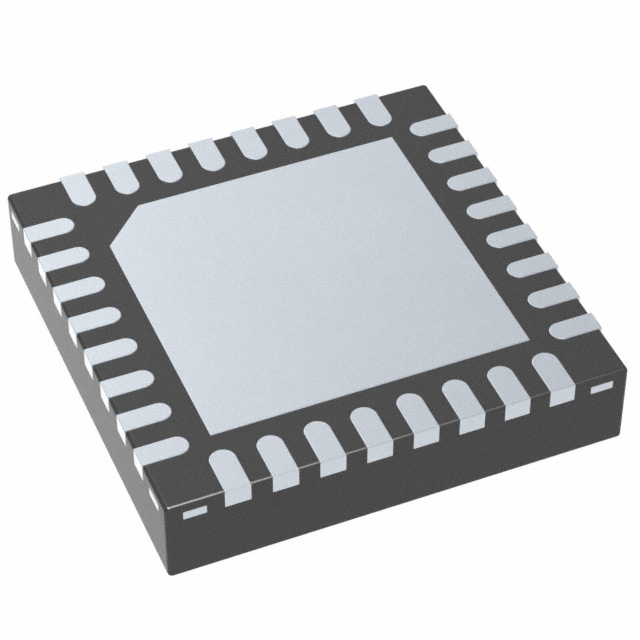


 工商网监
湘ICP备2023018690号
工商网监
湘ICP备2023018690号

