www.ti.com
User’s Guide
ADS8555EVM-PDK Evaluation Module
ABSTRACT
This user's guide describes the operation and use of the ADS8555 evaluation module (EVM). The ADS8555 is
a 6-channel, simultaneous sampling, 16-bit successive approximation (SAR) analog-to-digital converter (ADC).
Each input channel on the device can support true bipolar input ranges up to ±12 V. The device includes a
programmable, internally buffered voltage reverence. The ADC includes a serial programming interface (SPI)
interface and a parallel interface (word and byte mode) for data communication. Device configuration is achieved
through simple static digital input pins (hardware mode) or through communications to the SPI interface (control
register configuration in software mode). This user's guide covers the circuit description, schematic diagram, and
bill of materials for the ADS8555 circuit board. This EVM hardware and software can also be used to support
the ADS8556, ADS8557, and ADS8558 devices from this family. Other devices can be tested by desoldering the
ADC and reprogramming the EVM (see Section 6.3). Detailed instructions for using other family members are
provided later in this document.
SLAU298A – NOVEMBER 2009 – REVISED MAY 2021
Submit Document Feedback
ADS8555EVM-PDK Evaluation Module
Copyright © 2021 Texas Instruments Incorporated
1
�Table of Contents
www.ti.com
Table of Contents
1 ADS8555EVM-PDK Overview.................................................................................................................................................3
1.1 ADS8555EVM-PDK Features............................................................................................................................................ 3
1.2 ADS8555EVM Features.....................................................................................................................................................3
2 EVM Analog Interface.............................................................................................................................................................4
2.1 ADC Supply, Input, Voltage Reference, and Digital Connections...................................................................................... 4
2.2 ADC Amplifier Drive........................................................................................................................................................... 5
3 Digital Interface.......................................................................................................................................................................6
3.1 Parallel Interface................................................................................................................................................................ 6
3.2 Serial Interface (SPI)..........................................................................................................................................................6
3.3 I2C Bus and EEPROM....................................................................................................................................................... 6
3.4 Connections to the PHI Connector.....................................................................................................................................7
4 Power Supplies....................................................................................................................................................................... 8
4.1 External Power Connections and Test Points.................................................................................................................... 8
4.2 Low-Dropout Regulator (TPS7A3001 for HVSS)............................................................................................................... 8
4.3 Low-Dropout Regulator (TPS7A4700 for AVDD, HVDD)................................................................................................... 9
5 Installing the ADS8555EVM Software................................................................................................................................. 10
6 ADS8555EVM Operation...................................................................................................................................................... 12
6.1 Connecting the Hardware and Running the GUI..............................................................................................................12
6.2 Jumper Settings for the ADS8555EVM............................................................................................................................13
6.3 Modifying Hardware and Using Software to Evaluate Other Devices in the Family.........................................................14
6.4 EVM GUI Global Settings for ADC Control and Registers............................................................................................... 15
6.5 Time Domain Display....................................................................................................................................................... 16
6.6 Frequency Domain Display.............................................................................................................................................. 17
6.7 Histogram Display............................................................................................................................................................ 18
7 Bill of Materials, Layout, and Schematics.......................................................................................................................... 19
7.1 Bill of Materials.................................................................................................................................................................19
7.2 Board Layout....................................................................................................................................................................22
7.3 Schematics.......................................................................................................................................................................23
8 Revision History................................................................................................................................................................... 26
Trademarks
Keysight™ is a trademark of Keysight Technologies.
LabVIEW™ is a trademark of National Instruments.
Microsoft® and Windows® are registered trademarks of Microsoft Corporation.
All trademarks are the property of their respective owners.
2
ADS8555EVM-PDK Evaluation Module
SLAU298A – NOVEMBER 2009 – REVISED MAY 2021
Submit Document Feedback
Copyright © 2021 Texas Instruments Incorporated
�ADS8555EVM-PDK Overview
www.ti.com
1 ADS8555EVM-PDK Overview
This document describes how to connect the EVM to your computer and test equipment to evaluate device
performance and understand device features. The document also describes how to install and use the
associated evaluation module software.
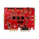
1.1 ADS8555EVM-PDK Features
Figure 1-1 shows the proper component connection for the ADS8555EVM. The ADS8555 evaluation module kit
includes the following features:
•
•
•
•
Hardware and software required for diagnostic testing as well as accurate performance evaluation of the
ADS8555 ADC.
Digital and analog interface power with universal serial bus (USB) power. External power is required for the
high-voltage ±15-V supply.
Easy-to-use evaluation software for the 64-bit Microsoft® Windows®7, Windows® 8, and Windows® 10
operating systems.
Precision host interface (PHI) controller translates the USB (2.0) or higher to parallel or serial digital
communications.
+15V, -15V, GND
xx
xx
xx
xx
xx
xx
xx
ADS8555EVM
Signal
Source
PHI Board
x
Signal
Source
ADS8555
GUI
x
x
x
Included in kit
Figure 1-1. System Connection for Evaluation
x
1.2 ADS8555EVM Features
•
•
•
•
•
•
Six input channels connected to external single-ended signals that are source applied to subminiature version
A (SMA) connectors or headers.
Serial and parallel interface connects to the PHI controller via a 60-pin connector (J2).
High-voltage power supplies (HVDD and HVSS) are not included. Connect common lab supplies via screw
terminal J1.
Analog low-voltage supplies (AVDD = 5 V) are generated using an external 15-V supply and a low-dropout
regulator (LDO). HVDD (12-V supply) is also generated using the 15-V supply and an LDO. HVSS (–12-V
supply) is generated using the –15-V supply and an LDO.
Digital low-voltage supply (DVDD = 3.3 V) is generated using USB power from the PHI controller.
Integrated or external voltage reference options are available.
SLAU298A – NOVEMBER 2009 – REVISED MAY 2021
Submit Document Feedback
ADS8555EVM-PDK Evaluation Module
Copyright © 2021 Texas Instruments Incorporated
3
�EVM Analog Interface
www.ti.com
2 EVM Analog Interface
The ADS8555EVM is an evaluation module built using a two-board modular EVM system. One board is a digital
controller (PHI), and the other board contains the ADC and associated analog circuitry. Both boards and the
associated cables form the ADS8555EVM-PDK.
2.1 ADC Supply, Input, Voltage Reference, and Digital Connections
Figure 2-1 shows the decoupling on AVDD, BVDD, HVDD, and HVSS and the voltage reference. The decoupling
capacitors match the recommendations in the ADS8555 data sheet. The layout (see Figure 7-1) uses the
shortest possible connections to the decoupling capacitors and connects the ground end to the GND plane
using vias. The ADS8555 can use an external or internal voltage reference. This reference can be selected by
changing the position of JP06 to INT for internal or EXT for external. Figure 2-1 also shows the analog input
signal and digital signal connections.
AVDD
C1
1µF
C2
1µF
C3
1µF
C4
1µF
C6
1µF
C7
1µF
U 2A
GND
CH_A0
GND
CONVST_A
U 2B
26
34
35
40
41
46
47
50
60
C28 HVDD
1µF
31
R97
CH_A0
23
CONVS T_A
49.9
AV DD
AV DD
AV DD
AV DD
AV DD
AV DD
AV DD
AV DD
AV DD
AGND
AGND
AGND
AGND
AGND
AGND
AGND
AGND
AGND
AGND
AGND
AGND
BV DD
BGND
HVDD
HVSS
BVDD
9
33
C71
10uF
GND
25
32
37
38
43
44
49
52
53
55
57
59
54
CH_A1
36
CH_B0
39
CONVST_B
R98
REFC_A
CH_A1
CH_B0
22
8
GND
30
HVSS
GND
56
CH_B1
42
CH_C0
45
CONVST_C
R99
REFC_B
CH_B1
CH_C 0
21
CONVS T_C
49.9
ADS8555SPMR
C5
1µF
C27
1µF
C73
10uF
GND
CH_C1
58
REFC_C
48
CH_C 1
GND
GND
51
GND
CS /FS
RD
WOR D/B YTE
PAR/S ER
CONVS T_B
49.9
C72
10uF
GND
BU SY/INT
RA NGE/XC LK
HW/SW
REFEN/WR
STB Y
RES ET
REFIO
TP8
DB0/SEL _A
DB1/SEL _B
DB2/SEL _C
DB3/DCIN_C
DB4/DCIN_B
DB5/DCIN_A
DB6/SC LK
DB7/HBEN/DCEN
DB8/SDO_A
DB9/SDO_B
DB10/SDO_C
DB11
DB12
DB13/SDI
DB14/REFBU FEN
DB15
18
27
62
63
24
28
19
20
29
61
17
16
15
14
13
12
11
10
7
6
5
4
3
2
1
64
ADS8555SPMR
VREF
R71
49.9
R72
49.9
R74
R73
49.9
R75
49.9
R77
49.9
R46
49.9
R78
49.9
49.9
R79
R80
49.9
49.9
R81
49.9
R82
49.9 R83
R84
49.9
49.9 R85
R86
49.9
49.9 R87
R35
49.9
49.9
R88
49.9 R89
R90
49.9
49.9 R91
R92
49.9
49.9 R93
R94
49.9
49.9 R95
R96
49.9
49.9
49.9
R76
BUSY/INT
RANGE/XCLK
HW/SW
REFEN/WR
ST BY
RESET
CS/FS
~RD_RETURN
~RD
WORD/BYTE
PAR/SER
DB0/SEL_A
DB1/SEL_B
DB2/SEL_C
DB3/DCIN_C
DB4/DCIN_B
DB5/DCIN_A
DB6/SCLK
SCLK_RET URN
DB7/HBEN/DCEN
DB8/SDO_A
DB9/SDO_B
DB10/SDO_C
DB11
DB12
DB13/SDI
DB14/REFBUFEN
DB15
JP06
C40
470nF
25V
INT
1
2
3
EXT
AVDD
U6A
2
3
C39
100nF
VIN
VOUT
TRIM/NR
TEMP
R47
6
5
0
GND
4
GND
C37
1µF R48
0.22
REF5025AIDGKR
GND
GND
C38
10uF
GND
Figure 2-1. ADC Signal and Supply Connection
4
ADS8555EVM-PDK Evaluation Module
SLAU298A – NOVEMBER 2009 – REVISED MAY 2021
Submit Document Feedback
Copyright © 2021 Texas Instruments Incorporated
�www.ti.com
EVM Analog Interface
2.2 ADC Amplifier Drive
Figure 2-2 shows the op amp configuration for each ADC drive input. The default configuration is a noninverting
buffer configuration. The gain of this circuit can be adjusted by changing R03 and R02 as needed. C02 can
be used to limit the amplifier bandwidth or compensate the amplifier. R01 and C01 can also be used to create
a low-pass filter. Jumper JP00 can be used to completely bypass the amplifier. This diagram only shows one
channel, but this circuit is repeated six times. For other channels, see Figure 7-2.
BYPS
R03
R02
DNP
1.00k
TP9
A0
1
2
3
0
JP00
AMP
C02
DNP
100pF
HVDD
R04
GND
C03
5
TP10
A0in
100nF
GND
4
J00
1
C05
220pF
1
R01
3
2
1.00k
2
3
4
5
CH_A0
24.9
C01
1000pF
U00
OPA209AIDBVR
GND
C04
100nF
HVSS
GND
GND
GND
Figure 2-2. Amplifier Drive Circuit
SLAU298A – NOVEMBER 2009 – REVISED MAY 2021
Submit Document Feedback
ADS8555EVM-PDK Evaluation Module
Copyright © 2021 Texas Instruments Incorporated
5
�Digital Interface
www.ti.com
3 Digital Interface
As noted in Section 1.1, the EVM interfaces with the PHI and communicates with the computer over the
USB. There are two devices on the EVM with which the PHI communicates: the ADS8555 ADC (over SPI or
parallel) and the EEPROM (over I2C). The electrically erasable programmable read-only memory (EEPROM)
comes preprogrammed with the information required to configure and initialize the ADS8555 platform. When the
hardware is initialized, the EEPROM is no longer used.
3.1 Parallel Interface
The parallel interface signals are generated on the PHI controller and are connected through J2. Each of these
signals has a 47-Ω resistor between the device and the controller to slow down the signal edges in order to
minimize signal overshoot. The digital signals can be monitored on the J3, J4, and J5 test headers.
3.2 Serial Interface (SPI)
The ADS8555 ADC uses SPI serial communication in mode 1 (CPOL = 0 and CPHA= 1). Because the serial
clock (SCLK) frequency can be as fast as 36 MHz, the ADS8555EVM offers 47-Ω resistors between the
controller and device to aid with signal integrity. Typically, in high-speed SPI communication, fast signal edges
can cause overshoot; these 47-Ω resistors slow down the signal edges in order to minimize signal overshoot.
3.3 I2C Bus and EEPROM
The circuit shown in Figure 3-1 is used with the EVM controller (PHI) for EVM identification. This circuit is not
required by the ADS8555 for operation. The switch (S1) is write protected and does not need to be changed for
EVM operation.
EVM_ID_PWR
EVM_ID_PWR
C74
R101
10.0k
U3
1
2
3
4
A0
VCC
A1
WP
A2
SCL
VSS
SDA
8
7
S1
1
100nF
GND
6
EVM_ID_SCL
5
EVM_ID_SDA
2
3
BR24G32FVT-3AGE2
GND
R102
EVM_ID_WP
0
GND
Figure 3-1. I2C Bus and EEPROM
6
ADS8555EVM-PDK Evaluation Module
SLAU298A – NOVEMBER 2009 – REVISED MAY 2021
Submit Document Feedback
Copyright © 2021 Texas Instruments Incorporated
�www.ti.com
Digital Interface
3.4 Connections to the PHI Connector
Connector J2 is used to connect the PHI digital controller printed circuit board (PCB) to the ADS8555EVM. This
connector has all the digital signals as well as the BVDD supply. The power for the BVDD supply is from the
USB connection. This connector also provides I2C signals that are used on the EEPROM identification circuit.
The digital signals can be monitored on the J3, J4, and J5 test headers. Figure 3-2 provides a schematic
showing the various connections to the PHI connector.
BVDD
R49
100k
R50
100k
J4
WORD/BYTE
RESET
RANGE/XCLK
STBY
CONVST_A
CONVST_B
CONVST_C
~RD
CS/FS
BUSY/INT
1
3
5
7
9
11
13
15
17
19
2
4
6
8
10
12
14
16
18
20
GND
J3
1
3
5
7
9
11
13
15
17
19
21
23
25
27
29
31
2
4
6
8
10
12
14
16
18
20
22
24
26
28
30
32
BVDD
D7
Zener
3.6V
TSW-116-07-G-D
BVDD
2
4
6
8
10
12
14
CONVST_A
16
CONVST_B
18
CONVST_C
20
CS/FS
22
24
~RD
26
~RD_RETURN
28
BUSY/INT
30
REFEN/WR
32
34
36
38
40
42
44
46
HW/SW
48
50
52
PAR/SER
54
C75
EVM_ID_SDA 56
10uF
EVM_ID_SCL 58
60
WORD/BYTE
RESET
RANGE/XCLK
STBY
TSW-110-07-G-D
DB0/SEL_A
DB1/SEL_B
DB2/SEL_C
DB3/DCIN_C
DB4/DCIN_B
DB5/DCIN_A
DB6/SCLK
DB7/HBEN/DCEN
DB8/SDO_A
DB9/SDO_B
DB10/SDO_C
DB11
DB12
DB13/SDI
DB14/REFBUFEN
DB15
TP1
5.5V
J2
2
4
6
8
10
12
14
16
18
20
22
24
26
28
30
32
34
36
38
40
42
44
46
48
50
52
54
56
58
60
DNP
1
3
5
7
9
11
13
15
17
19
21
23
25
27
29
31
33
35
37
39
41
43
45
47
49
51
53
55
57
59
1
3
5
7
9
11
13
15
17
19
21
23
25
27
29
31
33
35
37
39
41
43
45
47
49
51
53
55
57
59
DB0/SEL_A
DB1/SEL_B
DB2/SEL_C
DB3/DCIN_C
DB4/DCIN_B
DB5/DCIN_A
DB6/SCLK
DB7/HBEN/DCEN
DB8/SDO_A
DB9/SDO_B
DB10/SDO_C
DB11
DB12
DB13/SDI
DB14/REFBUFEN
DB15
SCLK_RETURN
EVM_ID_WP
EVM_ID_PWR
GND
R55
100k
R56
100k
R57
100k
MP1
MP2
GND
J5
REFEN/WR
HW/SW
PAR/SER
1
3
5
2
4
6
GND
GND
GND
GND
MP3
MP4
QTH-030-01-L-D-A
GND
GND
TSW-103-07-G-D
GND
Figure 3-2. Connections to PHI Connector
SLAU298A – NOVEMBER 2009 – REVISED MAY 2021
Submit Document Feedback
ADS8555EVM-PDK Evaluation Module
Copyright © 2021 Texas Instruments Incorporated
7
�www.ti.com
Power Supplies
4 Power Supplies
The ADS8555 device uses four power supplies: AVDD (5 V), BVDD (3.3 V), HVDD (12 V), and HVSS (–12 V).
The two high-voltage power supplies require an external ±15-V supply and are connected on a screw terminal
strip (J1). The ±15-V supplies are regulated from ±15 V to ±12 V for HVDD and HVSS. The digital voltage supply
(BVDD), is generated with the USB power. The analog supply (AVDD) is generated using the external 15-V
supply and an LDO to generate 5 V.
4.1 External Power Connections and Test Points
The screw terminal block J1 is used to connect the external high voltage supplies. These supplies are not
provided in the evaluation module kit and the expectation is that a low-noise lab supply is used to provide this
power (for example, Keysight™ E3632A). The high-voltage supplies have transient voltage suppressor diodes to
help protect the ADC from transients. These supplies are typically connected to ±15 V. For details on operation,
see the ADS8555 data sheet. Figure 4-1 also shows how each supply has a light-emitting diode (LED) monitor
for quick verification that power is applied.
3
2
1
J1
D1
D2
SMAJ 15A
SMAJ 15A
+15V
-15V
GND
C20
C26
10µF
10µF
GND
1
D3
APT2012LZGCK
Green
GND
BVDD
R20
6.65k
D4
APT2012LZGCK
Green
GND
R30
6.65k
1
1
AVDD
BVDD
D5
APT2012LZGCK
Green
2
R19
10.0k
HVDD
2
AVDD
1
R18
10.0k
2
HVSS
GND
HVDD
2
HVSS
GND
D6
APT2012LZGCK
Green
GND
Figure 4-1. External Power Connections and Test Points
4.2 Low-Dropout Regulator (TPS7A3001 for HVSS)
As shown in Figure 4-2, the –15-V external power is connected to the TPS7A3001 LDO to generate –12 V. This
LDO output can be programmed to different voltages by changing the feedback network R6 and R7. This LDO
was selected for low noise and flexibility.
-15V
R4
0
TP3
-15V
U4
8
C16
25V
10uF
5
OUT
R6
93.1k
EN
FB
6
7
GND
IN
HVSS
C19
50V
10nF
3
R5
1
2
0
C17
50V
10nF
C18
25V
10uF
NR /SS
R7
10.0k
DN C
NC
GND
PAD
4
9
GND
TPS7A3001DRBR
GND
GND
Figure 4-2. Low-Dropout Regulator (TPS7A3001 for HVSS)
8
ADS8555EVM-PDK Evaluation Module
SLAU298A – NOVEMBER 2009 – REVISED MAY 2021
Submit Document Feedback
Copyright © 2021 Texas Instruments Incorporated
�www.ti.com
Power Supplies
4.3 Low-Dropout Regulator (TPS7A4700 for AVDD, HVDD)
The 15-V external power is connected to two LDOs (TPS7A4700RGWR). One LDO generates AVDD (5 V), and
one generates HVDD (12 V). As shown in Figure 4-3, the TPS7A4700RGWR LDO output can be programmed
to different voltages by installing or uninstalling the resistors connected on pins 4-12. This LDO was selected for
low noise and flexibility.
+15V
AVDD
U5
R25
15
16
0
R29
C29
25V
22uF
13
EN
1
20
OUT
OUT
IN
IN
R28
0
3
SENSE
C30
25V
10uF
100k
NR
4
5
6
8
9
10
11
12
GND
14
6P4V2
6P4V1
3P2V
1P6V
0P8V
0P4V
0P2V
0P1V
19
18
17
2
NC
NC
NC
NC
GND
C36
1µF
25V
7
21
GND
PAD
TPS7A4700RGWR
R36 R37 R38 R39 R40 R45
DNP DNP
DNP DNP
0
0
0
0
0
0
GND
TP2
+15V
+15V
HVDD
GND
U1
R1
15
16
0
R3
C8
25V
22uF
13
IN
IN
EN
OUT
OUT
SENSE
R2
1
20
0
3
C9
25V
10uF
100k
4
5
6
8
9
10
11
12
GND
NR
6P4V2
6P4V1
3P2V
1P6V
0P8V
0P4V
0P2V
0P1V
NC
NC
NC
NC
GND
PAD
14
19
18
17
2
GND
C10
1µF
25V
7
21
TPS7A4700RGWR
R26 R27 R8 R9
DNP
DNP
0
0
0
0
R10 R15 R16 R17
DNP
DNP
0
0
0
0
GND
GND
Figure 4-3. Low-Dropout Regulator (TPS7A4700 for AVDD, HVDD)
SLAU298A – NOVEMBER 2009 – REVISED MAY 2021
Submit Document Feedback
ADS8555EVM-PDK Evaluation Module
Copyright © 2021 Texas Instruments Incorporated
9
�www.ti.com
Installing the ADS8555EVM Software
5 Installing the ADS8555EVM Software
Download the latest version of the EVM GUI installer from the Tools and Software folder of the ADS8555EVM
and run the GUI installer to install the EVM GUI software on your computer. Accept the license agreements and
follow the on-screen instructions shown in Figure 5-1 to complete the installation.
Figure 5-1. ADS8555 Software Installation Prompts
As a part of the ADS8555EVM GUI installation, a prompt with a Device Driver Installation (as shown in Figure
5-2) appears on the screen. Click Next to proceed.
Figure 5-2. Device Driver Installation Wizard Prompts
10
ADS8555EVM-PDK Evaluation Module
SLAU298A – NOVEMBER 2009 – REVISED MAY 2021
Submit Document Feedback
Copyright © 2021 Texas Instruments Incorporated
�Installing the ADS8555EVM Software
www.ti.com
The ADS8555EVM requires the LabVIEW™ run-time engine and may prompt for the installation of this software,
as shown in Figure 5-3, if not already installed.
Figure 5-3. LabVIEW™ Run-Time Engine Installation
Verify that C:\Program Files (x86)\Texas Instruments\ADS8555EVM is as shown in Figure 5-4 after these
installations.
Figure 5-4. ADS8555EVM GUI Folder Post-Installation
SLAU298A – NOVEMBER 2009 – REVISED MAY 2021
Submit Document Feedback
ADS8555EVM-PDK Evaluation Module
Copyright © 2021 Texas Instruments Incorporated
11
�www.ti.com
ADS8555EVM Operation
6 ADS8555EVM Operation
This section provides step-by-step instructions for connecting the ADS8555EVM to the computer and evaluating
the performance of the ADS8555.
6.1 Connecting the Hardware and Running the GUI
1. Set the jumpers according to Section 6.2.
2. Physically connect P2 of the PHI to J10 of the ADS8555EVM. Install the screws to assure a robust
connection.
3. Connect the USB on the PHI to the computer first.
a. LED D5 on the PHI lights up, indicating that the PHI is powered up.
b. LEDs D1 and D2 on the PHI start blinking to indicate that the PHI is booted up and communicating with
the PC; Figure 6-1 shows the resulting LED indicators.
4. As shown in Figure 6-2, start the software GUI. Notice that the LEDs blink slowly when the FPGA firmware is
loaded on the PHI. This process takes a few seconds, afterwards the AVDD and DVDD power supplies turn
on.
5. Connect the external ±15-V power supplies and GND to J1. This connection generates the AVDD, HVDD,
and HVSS supplies (HVDD = 12 V, HVSS = –12 V, and AVDD = 5 V).
6. Connect the signal generator. The default input range is ±10 V (or 10 Vpk). A common input signal applied is
a sinusoidal 1-kHz, 9.9-Vpk signal with a 0-V offset. This signal is adjusted just below the full-scale range to
avoid clipping.
+15V, -15V, GND
External Supply
Test point
headers
ADS8555EVM
PHI
Controler
Input signals
connected to first
two channels.
JP00 t JP05
Bypass amplifier
jumper
JP06
External/Internal
Vref configuration
Figure 6-1. ADS8555EVM Hardware Setup and LED Indicators
Select EVM GUI from
start menu, or
associated shortcut.
Figure 6-2. Launch the EVM GUI Software
12
ADS8555EVM-PDK Evaluation Module
SLAU298A – NOVEMBER 2009 – REVISED MAY 2021
Submit Document Feedback
Copyright © 2021 Texas Instruments Incorporated
�www.ti.com
ADS8555EVM Operation
6.2 Jumper Settings for the ADS8555EVM
The amplifiers and reference can be configured with jumpers. The amplifier jumpers (JP00–JP05) determine if
the amplifier is used or if an external signal is directly connected to the ADC input. JP06 is used to select either
the internal or external reference option. Make sure that the GUI configuration for the device reference matches
the setting of JP06. The GUI software starts up in the internal reference mode, so make sure the JP06 is in the
INT position. Table 6-1 lists the various jumper settings for the ADS8555EVM.
Table 6-1. Jumper Settings
JUMPER
SETTING
DEFAULT FUNCTION
JP00–JP05
AMP/BYPS
AMP
These eight jumpers determine if the amplifier is used to buffer the inputs signals
or if the amplifier is bypassed. Choosing AMP connects the amplifier between each
SMA connector (JP00–JP05) and the ADC input. The default amplifier configuration
is noninverting (gain = 1 V/V). The amplifier gain configuration can be adjusted by
soldering and desoldering different resistors. Choosing the bypass configuration (BYPS)
connects the SMA connectors directly to the ADC input.
JP06
INT/EXT
INT
This jumper selects either the internal or external mode on the voltage reference. Using
the internal mode disconnects the external reference. Using the external mode connects
the external REF5025 2.5-V reference to the ADC reference input. Make sure that the
GUI settings for the voltage reference match the setting on this jumper.
SLAU298A – NOVEMBER 2009 – REVISED MAY 2021
Submit Document Feedback
ADS8555EVM-PDK Evaluation Module
Copyright © 2021 Texas Instruments Incorporated
13
�www.ti.com
ADS8555EVM Operation
6.3 Modifying Hardware and Using Software to Evaluate Other Devices in the Family
The ADS8555 is part of a family of related devices. This EVM hardware and software support the entire family
because all the devices are pin-for-pin compatible. The Table 6-2 lists other compatible devices in the family. The
following procedure shows how to modify the hardware and software to evaluate the other devices in this family.
1. Desolder the ADS8555 and replace this device with the device you want to evaluate.
2. Enable the EEPROM for writing. This process is done by changing switch S2 to the WR_EN (top) position
using tweezers. Figure 6-3 details this process.
3. Connect the EVM and start the GUI as described in Figure 6-2.
4. Under the Tools menu in Figure 6-4, select Load EEPROM to load the EEPROM according to the device that
is currently installed. When this procedure is successfully completed, the status bar at the top of the software
updates according to the device installed on the hardware.
Table 6-2. Compatible Devices
DEVICE
RESOLUTION
PARALLEL
DATA RATE
SERIAL DATA
OTHER FEATURE
RATE
ADS8555
16
630
450
Does not have partial power-down mode
ADS8556
16
630
450
—
ADS8557
14
670
470
—
ADS8558
12
730
500
—
Use tweezers to change
position of switch S1
^WR_EN_ as shown to
allow the EPROM write
operation.
Figure 6-3. Enable EEPROM for Writing
1. On the ^tools_ menu
select ^load EEPROM_
3. After pressing ^load
EEPROM_ it will take a few
minutes to load the EEPROM.
2. Under ^Supported Devices_
select the desired devices and
press ^Load EEPROM_X
4. The top of the status bar on the
software will indicate what the EVM
connected has been updated to.
Figure 6-4. Configure EEPROM and Software for the New Device
14
ADS8555EVM-PDK Evaluation Module
SLAU298A – NOVEMBER 2009 – REVISED MAY 2021
Submit Document Feedback
Copyright © 2021 Texas Instruments Incorporated
�www.ti.com
ADS8555EVM Operation
6.4 EVM GUI Global Settings for ADC Control and Registers
Figure 6-5 shows the Register Map page. This page can only be accessed by selecting Software device mode.
Editing the CONFIG_REG configures the different ranges and voltage references available on the ADS8555.
See the ADS8555 data sheet for register field details. The left hand side of this GUI contains important
configurations such as interface selection, device mode, range selection, and sampling rate. These controls
are always available on the left hand side of the GUI regardless of which page is selected. Also, if Hardware
mode is used, the hardware input select pins on the device are set according the controls on the left hand side.
For example, when in hardware mode if the Parallel Interface is selected, than the PAR/SER pin on the device is
driven low by the PHI to select parallel interface mode.
Edit control
register contents
here.
Select different
^Pages_ here.
Select serial or
parallel digital
interface.
Select ^Software_
mode to access the
^Register Map Config_
Select sampling
rate.
Figure 6-5. EVM GUI Global Settings for ADC Control and Registers
SLAU298A – NOVEMBER 2009 – REVISED MAY 2021
Submit Document Feedback
ADS8555EVM-PDK Evaluation Module
Copyright © 2021 Texas Instruments Incorporated
15
�ADS8555EVM Operation
www.ti.com
6.5 Time Domain Display
The time domain display tool allows visualization of the ADC response to a given input signal. This tool is
useful for both studying the behavior and debugging any gross problems with the ADC or drive circuits. The
user can trigger a capture of the data of the selected number of samples from the ADS8555EVM, as per the
current interface mode settings indicated in Figure 6-6 by using the Capture button. The sample indices are on
the x-axis and there are two y-axes showing the corresponding output codes as well as the equivalent analog
voltages based on the specified reference voltage. Switching pages to any of the analysis tools described in the
subsequent sections causes calculations to be performed on the same set of data.
Figure 6-6. Time Domain Display
16
ADS8555EVM-PDK Evaluation Module
SLAU298A – NOVEMBER 2009 – REVISED MAY 2021
Submit Document Feedback
Copyright © 2021 Texas Instruments Incorporated
�www.ti.com
ADS8555EVM Operation
6.6 Frequency Domain Display
The spectral analysis tool, shown in Figure 6-7, is intended to evaluate the dynamic performance (SNR, THD,
SFDR, SINAD, and ENOB) of the ADS8555 ADC through single-tone sinusoidal signal fast Fourier transform
(FFT) analysis using the 7-term Blackman-Harris window setting. The FFT tool includes windowing options
that are required to mitigate the effects of noncoherent sampling (this discussion is beyond the scope of this
document). The 7-term Blackman-Harris window is the default option and has sufficient dynamic range to
resolve the frequency components of up to a 24-bit ADC. The None option corresponds to not using a window
(or using a rectangular window) and is not recommended.
Figure 6-7. Frequency Domain Display
SLAU298A – NOVEMBER 2009 – REVISED MAY 2021
Submit Document Feedback
ADS8555EVM-PDK Evaluation Module
Copyright © 2021 Texas Instruments Incorporated
17
�ADS8555EVM Operation
www.ti.com
6.7 Histogram Display
Noise degrades ADC resolution and the histogram tool can be used to estimate effective resolution, which
is an indicator of the number of bits of ADC resolution losses resulting from noise generated by the various
sources connected to the ADC when measuring a DC signal. The cumulative effect of noise coupling to the
ADC output from sources such as the input drive circuits, the reference drive circuit, the ADC power supply,
and the ADC itself is reflected in the standard deviation of the ADC output code histogram that is obtained by
performing multiple conversions of a DC input applied to a given channel. As shown in Figure 6-8, the histogram
corresponding to a DC input is displayed on clicking the Capture button.
Figure 6-8. Histogram Display
18
ADS8555EVM-PDK Evaluation Module
SLAU298A – NOVEMBER 2009 – REVISED MAY 2021
Submit Document Feedback
Copyright © 2021 Texas Instruments Incorporated
�www.ti.com
Bill of Materials, Layout, and Schematics
7 Bill of Materials, Layout, and Schematics
This section provides a bill of materials (BOM), a PCB layout for the ADS8555EVM, and schematics for the
ADS8555EVM.
7.1 Bill of Materials
Table 7-1 lists the bill of materials (BOM) for the ADS8555EVM.
Table 7-1. Bill of Materials (BOM)
DESIGNATOR
QTY
!PCB
VALUE
DESCRIPTION
PART NUMBER
MANUFACTURER
1
Printed circuit board
ADS8555
Any
C1–C7, C10, C27, C28,
C36, C37
12
1uF
CAP, CERM, 1 uF, 25 V, +/10%, X7R, 0603
C0603C105K3RACTU
Kemet
C01, C11, C21, C31, C41,
C51
6
1000pF
CAP, CERM, 1000 pF, 50 V,
+/- 5%, C0G/NP0, 0603
GRM1885C1H102JA01D
MuRata
C03, C04, C13, C14, C23,
C24, C33, C34, C43, C44,
C53, C54
12
0.1uF
CAP, CERM, 0.1 µF, 50 V,+/10%, X7R, AEC-Q200 Grade
1, 0603
C0603C104K5RACAUTO
Kemet
C05, C15, C25, C35, C45,
C55
6
220pF
CAP, CERM, 220 pF, 50 V, +/5%, C0G/NP0, 0603
06035A221JAT2A
AVX
C8, C29
2
22uF
CAP, CERM, 22 uF, 25 V, +/10%, X7R, 1210
GRM32ER71E226KE15L
MuRata
C9, C16, C18, C30, C38,
C71, C72, C73, C75
9
10uF
CAP, CERM, 10 uF, 25 V, +/10%, X5R, 0805
CL21A106KAFN3NE
Samsung ElectroMechanics
C17, C19
2
0.01uF
CAP, CERM, 0.01 µF, 50 V,+/10%, X7R, 0603
885012206089
Wurth Elektronik
C20, C26
2
10uF
CAP, CERM, 10 µF, 50 V,+/10%, X7R, AEC-Q200 Grade
1, 1206
CGA5L1X7R1H106K160AC
TDK
C39, C74
2
0.1uF
CAP, CERM, 0.1 uF, 50 V, +/10%, X7R, 0603
C0603C104K5RACTU
Kemet
C40
1
0.47uF
CAP, CERM, 0.47 uF, 25 V, +/GRM188R71E474KA12D
10%, X7R, 0603
MuRata
D1, D2
2
15V
Diode, TVS, Uni, 15 V, 24.4
Vc, 400 W, 16.4 A, SMA
SMAJ15A
Littelfuse
D3–D6
4
Green
LED, Green, SMD
APT2012LZGCK
Kingbright
3.6V
Diode, Zener, 3.6 V, 500 mW,
SOD-123
MMSZ4685T1G
ON Semiconductor
D7
1
H1–H4
4
Hex Standoff Threaded #4-40
Aluminum 0.250" (6.35mm)
1/4"
1891
Keystone
H5–H8
4
MACHINE SCREW PAN
PHILLIPS, 5/16", 4-40
PMSSS 440 0031 PH
B&F Fastener Supply
H13, H14
2
Machine Screw Pan PHILLIPS
RM3X4MM 2701
M3
APM HEXSEAL
H15, H16
2
ROUND STANDOFF M3
STEEL 5MM
9774050360R
Wurth Elektronik
J00–J05
6
SMA Straight Jack, Gold, 50
Ohm, TH
901-144-8RFX
Amphenol RF
J1
1
Terminal Block, 3.5mm Pitch,
3x1, TH
ED555/3DS
On-Shore
Technology
J2
1
Header(Shrouded), 19.7mil,
30x2, Gold, SMT
QTH-030-01-L-D-A
Samtec
J3
1
Header, 100mil, 16x2, Gold,
TH
TSW-116-07-G-D
Samtec
J4
1
Header, 100mil, 10x2, Gold,
TH
TSW-110-07-G-D
Samtec
J5
1
Header, 100mil, 3x2, Gold, TH TSW-103-07-G-D
Samtec
SLAU298A – NOVEMBER 2009 – REVISED MAY 2021
Submit Document Feedback
ADS8555EVM-PDK Evaluation Module
Copyright © 2021 Texas Instruments Incorporated
19
�Bill of Materials, Layout, and Schematics
www.ti.com
Table 7-1. Bill of Materials (BOM) (continued)
DESIGNATOR
QTY
JP00–JP06
7
R1, R2, R03, R4, R5, R13,
R23, R25, R28, R33, R43,
R53, R102
13
0
RES, 0, 5%, 0.1 W, AEC-Q200
CRCW06030000Z0EA
Grade 0, 0603
Vishay-Dale
R01, R11, R21, R31, R41,
R51
6
1.00k
RES, 1.00 k, 0.1%, 0.1 W,
0603
RT0603BRB071KL
Yageo America
R3, R29
2
100k
RES, 100 k, 1%, 0.1 W, AECQ200 Grade 0, 0603
CRCW0603100KFKEA
Vishay-Dale
R04, R14, R24, R34, R44,
R54
6
24.9
RES, 24.9, 1%, 0.1 W, 0603
RC0603FR-0724R9L
Yageo
R6
1
93.1k
RES, 93.1 k, 1%, 0.1 W, 0603
RC0603FR-0793K1L
Yageo
R7, R18, R19, R101
4
10.0k
RES, 10.0 k, 1%, 0.1 W, 0603
RC0603FR-0710KL
Yageo
R8, R10, R16, R27, R36,
R39
6
0
RES, 0, 5%, 0.063 W, 0402
RC0402JR-070RL
Yageo America
R20, R30
2
6.65k
RES, 6.65 k, 1%, 0.063 W,
AEC-Q200 Grade 0, 0402
CRCW04026K65FKED
Vishay-Dale
R35, R46, R71– R99
31
49.9
RES, 49.9, 1%, 0.063 W, AECCRCW040249R9FKED
Q200 Grade 0, 0402
Vishay-Dale
R47
1
0
RES, 0, 1%, 0.1 W, AEC-Q200
RMCF0603ZT0R00
Grade 0, 0603
Stackpole Electronics
Inc
R48
1
0.22
RES, 0.22, 1%, 0.1 W, AECQ200 Grade 0, 0603
ERJ-3RQFR22V
Panasonic
R49, R50, R55, R56, R57
5
100k
RES, 100 k, 1%, 0.0625 W,
0402
RC0402FR-07100KL
Yageo America
S1
1
Switch, Slide, SPDT 100mA,
SMT
CAS-120TA
Copal Electronics
SH-JP00–SH-JP06
7
Shunt, 100mil, Flash Gold,
Black
SPC02SYAN
Sullins Connector
Solutions
TP2–TP23
22
Test Point, Miniature, Black,
TH
5001
Keystone
6
2.2 nV/rtHz, 18 MHz,
Precision, RRO, Operational
Amplifier, 4.5 to 36 V, -40
to 125 degC, 5-pin SOT23
(DBV5), Green (RoHS & no
Sb/Br)
OPA209AIDBVR
Texas Instruments
U1, U5
2
36V, 1A, 4.17μVRMS,
RF Low-Dropout (LDO)
TPS7A4700RGWR
Voltage Regulator, RGW0020A
(VQFN-20)
Texas Instruments
U2
1
16 Bit Analog to Digital
Converter 6 Input 1 SAR 64LQFP (10x10)
ADS8555SPMR
Texas Instruments
U3
1
I2C BUS EEPROM (2-Wire),
TSSOP-B8
BR24G32FVT-3AGE2
Rohm
1
Vin -3V to -36V,
-200mA, Ultra-Low-Noise,
High-PSRR, Low-Dropout
(LDO) Linear Regulator,
DRB0008A (VSON-8)
TPS7A3001DRBR
Texas Instruments
U6
1
3 µVpp/V Noise, 3
ppm/°C Drift Precision
Series Voltage Reference,
DGK0008A (VSSOP-8)
REF5025AIDGKR
Texas Instruments
C02, C12, C22, C32, C42,
C52
0
CAP, CERM, 100 pF, 50 V, +/5%, C0G/NP0, 0603
885012006057
Wurth Elektronik
U00–U05
U4
20
VALUE
1x2
100pF
DESCRIPTION
PART NUMBER
MANUFACTURER
Header, 100mil, 3x1, Tin, TH
PEC03SAAN
Sullins Connector
Solutions
ADS8555EVM-PDK Evaluation Module
SLAU298A – NOVEMBER 2009 – REVISED MAY 2021
Submit Document Feedback
Copyright © 2021 Texas Instruments Incorporated
�www.ti.com
Bill of Materials, Layout, and Schematics
Table 7-1. Bill of Materials (BOM) (continued)
DESIGNATOR
QTY
FID1, FID2, FID3
0
R02, R12, R22, R32, R42,
R52
0
R9, R15, R17, R26, R37,
R38, R40, R45
0
TP1
0
VALUE
DESCRIPTION
PART NUMBER
MANUFACTURER
Fiducial mark. There is nothing
N/A
to buy or mount.
N/A
1.00k
RES, 1.00 k, 0.1%, 0.1 W,
0603
RT0603BRB071KL
Yageo America
0
RES, 0, 5%, 0.063 W, 0402
RC0402JR-070RL
Yageo America
Test Point, Miniature, Black,
TH
5001
Keystone
SLAU298A – NOVEMBER 2009 – REVISED MAY 2021
Submit Document Feedback
ADS8555EVM-PDK Evaluation Module
Copyright © 2021 Texas Instruments Incorporated
21
�Bill of Materials, Layout, and Schematics
www.ti.com
7.2 Board Layout
Figure 7-1 shows the PCB layout for the ADS8555EVM.
Figure 7-1. Board Layout
22
ADS8555EVM-PDK Evaluation Module
SLAU298A – NOVEMBER 2009 – REVISED MAY 2021
Submit Document Feedback
Copyright © 2021 Texas Instruments Incorporated
�www.ti.com
Bill of Materials, Layout, and Schematics
7.3 Schematics
Figure 7-2 shows a schematic for the amplifier drive section of the ADS8555EVM. The amplifier is by default a buffer and can be bypassed by using a
jumper.
BYPS
JP0 0
1
TP9
A0
2
3
R03
0
AM P
C02
DNP
100p F
R02
DNP
1.00k
HVDD
R04
2
U00
OPA209 AIDBVR
GND
GND
R41
1
AM P
BYPS
1
0
2
2
3
4
5
C41
1000 pF
U04
OPA209 AIDBVR
C44
GND
100n F
HVS S
GND
TP11
A1
GND
2
3
R13
R12
DNP
1.00k
C45
220p F
3
1.00k
C12
JP0 1
CH_C0
24.9
100n F
GND
1
4
J04
GND
R44
C43
TP14
C0in
100n F
GND
GND
DNP
100p F
TP13
C0
HVDD
C04
HVS S
JP0 4
0
5
3
4
5
C01
1000 pF
R43
R42
DNP
1.00k
AM P
DNP
100p F
C05
220p F
3
1.00k
2
C42
5
R01
1
CH_A0
24.9
BYPS
C03
100n F
GND
1
4
1
2
3
GND
TP10
A0in
J00
GND
HVDD
R11
C11
1000 pF
HVS S
U01
OPA209 AIDBVR
C14
0
GND
C53
J05
1
R51
3
AM P
BYPS
1
0
TP17
B0
2
GND
CH_B0
24.9
5
4
R21
C25
220p F
100n F
GND
1
J02
3
2
3
4
5
1.00k
2
GND
GND
R24
C23
TP18
B0in
1
U05
OPA209 AIDBVR
C54
100n F
HVS S
GND
HVDD
GND
C51
1000 pF
2
3
R23
2
3
4
5
1.00k
JP0 2
CH_C1
C55
220p F
100n F
GND
1
4
GND
R54
24.9
TP16
C1in
GND
R22
DNP
1.00k
TP15
C1
HVDD
GND
100n F
GND
C22
DNP
100p F
JP0 5
5
2
3
4
5
1.00k
R53
R52
DNP
1.00k
3
AM P
DNP
100p F
C15
220p F
BYPS
C52
5
4
2
CH_A1
24.9
J01
1
R14
C13
100n F
GND
1
1
2
3
GND
TP12
A1in
C21
1000 pF
U02
OPA209 AIDBVR
C24
GND
100n F
HVS S
GND
GND
GND
C32
AM P
JP0 3
1
BYPS
R33
0
TP19
B1
2
3
DNP
100p F
R32
DNP
1.00k
HVDD
GND
C33
5
R31
3
C31
1000 pF
2
3
4
5
1.00k
2
CH_B1
C35
220p F
100n F
GND
1
4
1
R34
24.9
TP20
B1in
J03
U03
OPA209 AIDBVR
C34
GND
100n F
HVS S
GND
GND
GND
Figure 7-2. Amplifier Drive Schematic
SLAU298A – NOVEMBER 2009 – REVISED MAY 2021
Submit Document Feedback
ADS8555EVM-PDK Evaluation Module
Copyright © 2021 Texas Instruments Incorporated
23
�Bill of Materials, Layout, and Schematics
www.ti.com
Figure 7-3 shows the LDOs used to generate the AVDD, HVDD, and HVSS supplies.
TP2
+15 V
+15 V
HVDD
U1
R1
0
R3
C8
25V
22uF
15
16
IN
IN
13
EN
OUT
OUT
SENSE
R2
1
20
-15V
0
3
C9
25V
10uF
100k
4
5
6
8
9
10
11
12
GND
6P4V2
6P4V1
3P2V
1P6V
0P8V
0P4V
0P2V
0P1V
NR
14
NC
NC
NC
NC
19
18
17
2
GND
PAD
7
21
R4
0
TP3
-15V
U4
GND
8
C10
1µF
25V
C16
25V
10uF
TPS7A47 00RGWR
R26 R27 R8 R9
DN0
P
DN0
P
0
0
R10 R15 R16 R17
P
P
0 DN0
0 DN0
C19
50V
10nF
GND
GND
HVSS
OUT
IN
5
EN
6
NR/SS
7
DNC
3
NC
R5
1
R6
93.1 k
FB
GND
PAD
2
0
C17
50V
10nF
C18
25V
10uF
R7
10.0 k
4
9
GND
TPS7A30 01DRBR
GND
GND
GND
+15 V
HVSS
HVDD
AVDD
2
1
0
3
D1
AVDD
U5
R25
BVDD
J1
HVSS
D2
R18
10.0 k
R19
10.0 k
HVDD
AVDD
R20
6.65 k
BVDD
GND
GND
D4
APT 2012LZ GCK
Gree n
13
EN
4
5
6
8
9
10
11
12
GND
1
D5
APT 2012LZ GCK
Gree n
2
D3
APT 2012LZ GCK
Gree n
2
1
10µ F
IN
IN
OUT
OUT
SENSE
R28
1
20
0
3
C30
25V
10uF
100k
C26
10µ F
2
C20
1
-15V
2
+15 V
R29
C29
25V
22uF
R30
6.65 k
SMAJ15 A
1
SMAJ15 A
15
16
D6
APT 2012LZ GCK
Gree n
GND
6P4V2
6P4V1
3P2V
1P6V
0P8V
0P4V
0P2V
0P1V
NR
14
NC
NC
NC
NC
19
18
17
2
GND
PAD
7
21
GND
C36
1µF
25V
TPS7A47 00RGWR
GND
GND
GND
GND
R36 R37 R38 R39 R40 R45
P DN0
P
P DN0
P
0 DN0
0 DN0
GND
TP21
GND
TP22
GND
TP23
GND
GND
GND
GND
GND
Figure 7-3. LDO Schematic
24
ADS8555EVM-PDK Evaluation Module
SLAU298A – NOVEMBER 2009 – REVISED MAY 2021
Submit Document Feedback
Copyright © 2021 Texas Instruments Incorporated
�www.ti.com
Bill of Materials, Layout, and Schematics
Figure 7-4 shows the ADC decoupling, digital connections, and reference connections.
AVDD
C1
1µ F
C2
1µ F
C3
1µ F
C4
1µ F
C6
1µ F
C7
1µ F
GND
GND
U2B
26
35
40
41
46
47
50
60
25
AGND
AGND
AGND
AGND
AGND
AGND
AGND
AGND
AGND
AGND
AGND
AGND
BVDD
C28 HVDD
1µ F
32
37
38
43
44
49
BVDD
52
53
R49
100 k
55
57
R50
100 k
59
J4
9
BVDD
BGND
8
31
HVDD
HVSS
30
WORD/BYTE
RESET
RANG E/XCLK
STBY
CONVST _A
CONVST _B
CONVST _C
~RD
CS/FS
BUSY/INT
GND
HVSS
GND
ADS85 55SPM R
C5
1µ F
C27
1µ F
GND
GND
1
3
5
7
9
11
13
15
17
19
2
4
6
8
10
12
14
16
18
20
BVDD
GND
U2A
CH_A0
CONVST _A
33
R97
23
C71
10u F
GND
CONVST_A
54
CH_A1
REFC_A
36
CH_B0
CONVST _B
R98
GND
39
CH_ B0
22
CONVST_B
56
CH_B1
R99
CH_ B1
45
CH_ C0
21
CONVST_C
49. 9
C73
10u F
GND
CH_C1
18
CS/FS
RD
WORD/BY TE
PAR/SER
19
DB0 /SE L_A
DB1 /SE L_B
DB2 /SE L_C
DB3 /DCIN_ C
DB4 /DCIN_ B
DB5 /DCIN_ A
DB6 /SCLK
DB7 /HBEN/DCE N
DB8 /SDO_A
DB9 /SDO_B
DB1 0/SDO_ C
DB1 1
DB1 2
DB1 3/SDI
DB1 4/REFBUF EN
DB1 5
REFC_B
42
CH_C0
CONVST _C
BUSY/INT
RANGE/XCLK
HW/SW
REFE N/WR
STBY
RESET
CH_ A1
49. 9
C72
10u F
TSW-110 -07-G-D
CH_ A0
49. 9
58
REFC_C
48
CH_ C1
51
REFIO
TP 8
VREF
ADS85 55SPM R
27
R71
62
63
20
R76
R78
29
61
R80
17
16
R82
15
14
R84
13
12
R86
11
10
R35
7
6
49. 9
49. 9
49. 9
R77
R46
49. 9
49. 9
R79
49. 9
49. 9
49. 9
R81
49. 9
49. 9 R83
49. 9
49. 9 R85
49. 9
49. 9 R87
49. 9
49. 9
49. 9 R89
49. 9
49. 9 R91
R92
49. 9
49. 9 R93
1
64
R75
R90
3
2
R73
49. 9
R88
5
4
49. 9
R74
24
28
49. 9
R72
R94
49. 9
49. 9 R95
R96
49. 9
BUSY/INT
RANG E/XCLK
HW/SW
REFEN/WR
STBY
RESET
CS/FS
~RD_RETURN
~RD
WORD/BYTE
PAR/SER
J3
DB0/SEL_ A
DB1/SEL_ B
DB2/SEL_ C
DB3/DCIN_C
DB4/DCIN_B
DB5/DCIN_A
DB6/SCL K
DB7/HBEN/DCEN
DB8/SDO _A
DB9/SDO _B
DB10/SDO_C
DB11
DB12
DB13/SDI
DB14/REFBUFEN
DB15
DB0/SEL_ A
DB1/SEL_ B
DB2/SEL_ C
DB3/DCIN_C
DB4/DCIN_B
DB5/DCIN_A
DB6/SCL K
SCLK_ RET URN
DB7/HBEN/DCEN
DB8/SDO _A
DB9/SDO _B
DB10/SDO_C
DB11
DB12
DB13/SDI
DB14/REFBUFEN
DB15
1
3
5
7
9
11
13
15
17
19
21
23
25
27
29
31
2
4
6
8
10
12
14
16
18
20
22
24
26
28
30
32
TEMP
GND
R56
100 k
3
2
EVM _ID_PWR
MP3
MP4
R57
100 k
J5
REFEN/WR
HW/SW
PAR/SER
1
3
5
2
4
6
TSW-103-07-G-D
EVM _ID_PWR
EVM _ID_PWR
C74
0
GND
1
C37
1µ F R48
0.2 2
A0
VCC
8
R101
10. 0k
S1
1
100 nF
GND
2
A1
WP
7
3
A2
SCL
6
EVM _ID_SCL
4
VSS
SDA
5
EVM _ID_SDA
2
3
GND
R102
GND
EVM _ID_WP
GND
BR24G32 FVT-3AGE2
GND
DB0/SEL_ A
DB1/SEL_ B
DB2/SEL_ C
DB3/DCIN_C
DB4/DCIN_B
DB5/DCIN_A
DB6/SCL K
DB7/HBEN/DCEN
DB8/SDO _A
DB9/SDO _B
DB10/SDO_C
DB11
DB12
DB13/SDI
DB14/REFBUFEN
DB15
SCLK_ RET URN
GND
R55
100 k
4
REF502 5AIDG KR
GND
GND
GND
GND
1
3
5
7
9
11
13
15
17
19
21
23
25
27
29
31
33
35
37
39
41
43
45
47
49
51
53
55
57
59
GND
R47
6
5
1
3
5
7
9
11
13
15
17
19
21
23
25
27
29
31
33
35
37
39
41
43
45
47
49
51
53
55
57
59
QT H-030 -01-L-D-A
U3
VOUT
TRIM/NR
2
4
6
8
10
12
14
16
18
20
22
24
26
28
30
32
34
36
38
40
42
44
46
48
50
52
54
56
58
60
GND
C40
470 nF
25V
INT
1
3
C39
100 nF
VIN
MP1
MP2
GND
U6A
2
2
4
WORD/BYTE
6
RESET
8
RANG E/XCLK
10
STBY
12
14
CONVST _A
16
CONVST _B
18
CONVST _C
20
CS/FS
22
24
~RD
26
~RD_RETURN
28
BUSY/INT
30
REFEN/WR
32
34
36
38
40
42
44
46
HW/SW
48
50
52
PAR/SER
54
C75
EVM _ID_SDA 56
10u F
EVM _ID_SCL 58
60
TSW-116 -07-G-D
BVDD
JP06
EXT
D7
Ze ner
3.6 V
GND
49. 9
AVDD
TP 1
5.5 V
DNP
J2
AVDD
AVDD
AVDD
AVDD
AVDD
AVDD
AVDD
AVDD
AVDD
34
C38
10u F
EVM _ID_WP
0
GND
GND
Figure 7-4. ADC, Reference, and Digital I/O Schematic
SLAU298A – NOVEMBER 2009 – REVISED MAY 2021
Submit Document Feedback
ADS8555EVM-PDK Evaluation Module
Copyright © 2021 Texas Instruments Incorporated
25
�Revision History
www.ti.com
8 Revision History
NOTE: Page numbers for previous revisions may differ from page numbers in the current version.
Changes from Revision * (November 2009) to Revision A (May 2021)
Page
• Changed entire document because of substantial changes in EVM hardware and software.............................1
26
ADS8555EVM-PDK Evaluation Module
SLAU298A – NOVEMBER 2009 – REVISED MAY 2021
Submit Document Feedback
Copyright © 2021 Texas Instruments Incorporated
�IMPORTANT NOTICE AND DISCLAIMER
TI PROVIDES TECHNICAL AND RELIABILITY DATA (INCLUDING DATA SHEETS), DESIGN RESOURCES (INCLUDING REFERENCE
DESIGNS), APPLICATION OR OTHER DESIGN ADVICE, WEB TOOLS, SAFETY INFORMATION, AND OTHER RESOURCES “AS IS”
AND WITH ALL FAULTS, AND DISCLAIMS ALL WARRANTIES, EXPRESS AND IMPLIED, INCLUDING WITHOUT LIMITATION ANY
IMPLIED WARRANTIES OF MERCHANTABILITY, FITNESS FOR A PARTICULAR PURPOSE OR NON-INFRINGEMENT OF THIRD
PARTY INTELLECTUAL PROPERTY RIGHTS.
These resources are intended for skilled developers designing with TI products. You are solely responsible for (1) selecting the appropriate
TI products for your application, (2) designing, validating and testing your application, and (3) ensuring your application meets applicable
standards, and any other safety, security, regulatory or other requirements.
These resources are subject to change without notice. TI grants you permission to use these resources only for development of an
application that uses the TI products described in the resource. Other reproduction and display of these resources is prohibited. No license
is granted to any other TI intellectual property right or to any third party intellectual property right. TI disclaims responsibility for, and you
will fully indemnify TI and its representatives against, any claims, damages, costs, losses, and liabilities arising out of your use of these
resources.
TI’s products are provided subject to TI’s Terms of Sale or other applicable terms available either on ti.com or provided in conjunction with
such TI products. TI’s provision of these resources does not expand or otherwise alter TI’s applicable warranties or warranty disclaimers for
TI products.
TI objects to and rejects any additional or different terms you may have proposed. IMPORTANT NOTICE
Mailing Address: Texas Instruments, Post Office Box 655303, Dallas, Texas 75265
Copyright © 2022, Texas Instruments Incorporated
�


 工商网监
湘ICP备2023018690号
工商网监
湘ICP备2023018690号
