bq27541
www.ti.com
SLUS861 – DECEMBER 2008
Single Cell Li-Ion Battery Fuel Gauge for Battery Pack Integration
Check for Samples: bq27541
FEATURES
APPLICATIONS
•
•
•
•
•
•
1
23
•
•
•
•
Battery Fuel Gauge for 1-Series Li-Ion
Applications
Microcontroller Peripheral Provides:
– Accurate Battery Fuel Gauging
– Internal Temperature Sensor for System
Temperature Reporting
– SHA-1/HMAC Authentication
– 96 Bytes of Non-Volatile Scratch Pad
FLASH
Battery Fuel Gauging Based on Patented
Impedance Track™ Technology
– Models Battery Discharge Curve for
Accurate Time-To-Empty Predictions
– Automatically Adjusts for Battery Aging,
Battery Self-Discharge, and
Temperature/Rate Inefficiencies
– Low-Value Sense Resistor (5 mΩ to 20 mΩ)
HDQ and I2C™ Interface Formats for
Communication with Host System
Small 12-pin 2,5 mm × 4 mm SON Package
Smartphones
PDAs
Digital Still and Video Cameras
Handheld Terminals
MP3 or Multimedia Players
DESCRIPTION
The Texas Instruments bq27541 Li-Ion battery fuel
gauge is a microcontroller peripheral that provides
fuel gauging for single-cell Li-Ion battery packs. The
device requires little system microcontroller firmware
development for accurate battery fuel gauging. The
bq27541 resides within the battery pack or on the
system’s main-board with an embedded battery
(nonremovable).
The bq27541 uses the patented Impedance Track™
algorithm for fuel gauging, and provides information
such as remaining battery capacity (mAh),
state-of-charge (%), run-time to empty (min.), battery
voltage (mV), and temperature (°C).
The bq27541 also features integrated support for
secure battery pack authentication, using the
SHA-1/HMAC authentication algorithm.
TYPICAL APPLICATION
Battery Pack
PACK+
Vcc
REGIN
LDO
REG25
BAT
SE
HDQ
bq27541
SDA
TS
SCL
SRP
PROTECTION
IC
Vss
SRN
PACK–
1
2
3
Please be aware that an important notice concerning availability, standard warranty, and use in critical applications of Texas
Instruments semiconductor products and disclaimers thereto appears at the end of this data sheet.
Impedance Track is a trademark of Texas Instruments.
I2C is a trademark of Phillips Corporation.
PRODUCTION DATA information is current as of publication date.
Products conform to specifications per the terms of the Texas
Instruments standard warranty. Production processing does not
necessarily include testing of all parameters.
Copyright © 2008, Texas Instruments Incorporated
�bq27541
SLUS861 – DECEMBER 2008
www.ti.com
This integrated circuit can be damaged by ESD. Texas Instruments recommends that all integrated circuits be handled with
appropriate precautions. Failure to observe proper handling and installation procedures can cause damage.
ESD damage can range from subtle performance degradation to complete device failure. Precision integrated circuits may be more
susceptible to damage because very small parametric changes could cause the device not to meet its published specifications.
DEVICE INFORMATION
AVAILABLE OPTIONS
PART NUMBER
bq27541DRZR
bq27541DRZT
(1)
PACKAGE
TA
COMMUNICATION
FORMAT
12-pin, 2,5-mm × 4-mm SON
–40°C to 85°C
I2C, HDQ (1)
TAPE and REEL
QUANTITY
3000
250
bq27541 is shipped in I2C mode
bq27541
(TOP VIEW)
SE
REG25
REGIN
BAT
Vcc
Vss
1
2
3
4
5
6
12
11
10
9
8
7
HDQ
SCL
SDA
TS
SRN
SRP
TERMINAL FUNCTIONS
TERMINAL
NAME
NO.
DESCRIPTION
TYPE
(1)
BAT
4
I
Cell-voltage measurement input. ADC input. Decouple with 0.1mF capacitor.
REG25
2
P
2.5V output voltage of the internal integrated LDO. Connect a minimum 0.47mF ceramic capacitor.
REGIN
3
P
The input voltage for the internal integrated LDO. Connect a 0.1mF ceramic capacitor.
SCL
11
I
Slave I2C serial communications clock input line for communication with system (Slave). Use with 10 kΩ
pull-up resistor (typical).
SDA
10
I/O
Slave I2C serial communications data line for communication with system (Slave). Open-drain I/O. Use
with 10 kΩ pull-up resistor (typical).
SE
1
O
Shutdown Enable output. Open-drain.
HDQ
12
I/O
HDQ serial communications line (Slave). Open-drain.
SRN
8
IA
Analog input pin connected to the internal coulomb counter where SRN is nearest the PACK- connection.
Connect to 5-mΩ to 20-mΩ sense resistor.
SRP
7
IA
Analog input pin connected to the internal coulomb counter where SRP is nearest the CELL- connection.
Connect to 5-mΩ to 20-mΩ sense resistor
TS
9
IA
Pack thermistor voltage sense (use 103AT-type thermistor). ADC input
Vcc
5
P
Processor power input. The minimum 0.47mF capacitor connected to REG25 should be close to Vcc.
Vss
6
P
Device ground
(1)
2
I/O = Digital input/output, IA = Analog input, P = Power connection
Submit Documentation Feedback
Copyright © 2008, Texas Instruments Incorporated
Product Folder Link(s): bq27541
�bq27541
www.ti.com
SLUS861 – DECEMBER 2008
ELECTRICAL SPECIFICATIONS
ABSOLUTE MAXIMUM RATINGS
over operating free-air temperature range (unless otherwise noted) (1)
VALUE
UNIT
–0.3 to 24
V
–0.3 to 2.75
V
Open-drain I/O pins (SDA, SCL, HDQ)
–0.3 to 6
V
BAT input, (pin 4)
–0.3 to 6
V
–0.3 to VCC + 0.3
V
VI
Regulator input, REGIN
VCC
Supply voltage range
VIOD
VBAT
VI
Input voltage range to all others (pins 1, 7, 8, 9)
ESD
Human Body Model (HBM), BAT pin
1.5
Human Body Model (HBM), all pins
2
kV
TF
Functional temperature range
–40 to 100
°C
Tstg
Storage temperature range
–65 to 150
°C
(1)
Stresses beyond those listed under absolute maximum ratings may cause permanent damage to the device. These are stress ratings
only, and functional operation of the device at these or any other conditions beyond those indicated under recommended operating
conditions is not implied. Exposure to absolute-maximum-rated conditions for extended periods may affect device reliability.
DISSIPATION RATINGS
(1)
(2)
PACKAGE (1)
TA ≤ 40°C
POWER RATING
DERATING FACTOR
TA ≤ 40°C
RqJA
12-pin DRZ (2)
482 mW
5.67 mW/°C
176°C/W
For the most current package and ordering information, see the Package Option Addendum at the end of this document, or see the TI
website at www.ti.com.
This data is based on using a 4-layer JEDEC high-K board with the exposed die pad connected to a Cu pad on the board. The board
pad is connected to the ground plane by a 2- × 2-via matrix.
RECOMMENDED OPERATING CONDITIONS
TA = -40°C to 85°C; typical values at TA = 25°C and V(REGIN) = VBAT = 3.6 V (unless otherwise noted)
PARAMETER
Test CONDITION
No operating restrictions
MIN
2.7
5.5
2.7
Supply voltage, REGIN
ICC
Normal operating mode current
I(SLP)
Low-power operating mode current
(1)
I(FULLSLP)
Low-power operating mode current
(1)
I(HIB)
Hibernate operating mode current
VOL
Output voltage low (HDQ, SDA, SCL,
SE)
IOL = 3 mA
VOH(PP)
Output high voltage (SE)
IOH = -1 mA
VCC–0.5
VOH(OD)
Output high voltage (HDQ, SDA, SCL)
External pull-up resistor connected to Vcc
VCC–0.5
VIL
Input voltage low (HDQ, SDA, SCL)
VIH
Input voltage high (HDQ, SDA, SCL)
V(A1)
Input voltage range (TS)
V(A2)
Input voltage range (BAT)
V(A3)
Input voltage range (SRP, SRN)
Ilkg
Input leakage current (I/O pins)
tPUCD
Power-up communication delay
(1)
Fuel gauge in NORMAL mode. ILOAD >
Sleep Current
(1)
(1)
MAX
2.45
VI
No FLASH writes
TYP
UNIT
V
131
mA
Fuel gauge in SLEEP mode.
ILOAD < Sleep Current
60
mA
Fuel gauge in FULLSLEEP mode.
ILOAD < Sleep Current
21
mA
Fuel gauge in HIBERNATE mode.
ILOAD < Hibernate Current
6
mA
0.4
V
V
V
–0.3
0.6
V
1.2
6
V
VSS–0.125
2
V
VSS–0.125
5
V
VSS–0.125
0.125
V
0.3
mA
250
ms
Specified by design. Not tested in production.
Submit Documentation Feedback
Copyright © 2008, Texas Instruments Incorporated
Product Folder Link(s): bq27541
3
�bq27541
SLUS861 – DECEMBER 2008
www.ti.com
POWER-ON RESET
TA = –40°C to 85°C, C(REG) = 0.47mF, 2.45 V < V(REGIN) = VBAT < 5.5 V; typical values at TA = 25°C and V(REGIN) = VBAT = 3.6 V
(unless otherwise noted)
PARAMETER
TEST CONDITIONS
VIT+
Positive-going battery voltage input at VCC
VHYS
Power-on reset hysteresis
MIN
TYP
MAX
2.05
2.20
2.31
UNIT
V
45
115
185
mV
2.5 V LDO REGULATOR (1)
TA = –40°C to 85°C, C(REG) = 0.47 mF, 2.45 V < V(REGIN) = VBAT < 5.5 V; typical values at TA = 25°C and V(REGIN) = VBAT = 3.6 V
(unless otherwise noted)
PARAMETER
Regulator output voltage,
REG25
VO
TEST CONDITION
MIN
NOM
MAX
UNIT
2.48
2.57
V
2.7 V ≤ V(REGIN) ≤ 5.5 V,
IOUT ≤ 16mA
TA = –40°C to 85°C
2.42
2.45 V ≤ V(REGIN) < 2.7 V (low
battery), IOUT ≤ 3mA
TA = –40°C to 85°C
2.4
2.7 V, IOUT ≤ 16 mA
V
280
VDO
Regulator dropout voltage
ΔV(REGTEMP)
Regulator output change
with temperature
V(REGIN) = 3.6 V,
IOUT = 16 mA
ΔV(REGLINE)
Line regulation
2.7 V ≤ V(REGIN) ≤ 5.5 V, IOUT = 16 mA
11
25
ΔV(REGLOAD)
Load regulation
0.2 mA ≤ IOUT ≤ 3 mA, V(REGIN) = 2.45 V
34
40
3 mA ≤ IOUT ≤ 16 mA, V(REGIN) = 2.7 V
31
IOS
(2)
(1)
(2)
Short circuit current limit
2.45 V, IOUT ≤ 3 mA
V(REG25) = 0 V,
TA = –40°C to 85°C
50
TA = –40°C to 85°C
mV
0.3%
TA = –40°C to 85°C
250
mV
mV
mA
LDO output current, IOUT, is the sum of internal and external load currents.
Specified by design. Not production tested.
INTERNAL TEMPERATURE SENSOR CHARACTERISTICS
TA = –40°C to 85°C, C(REG) = 0.47mF, 2.45 V < V(REGIN) = VBAT < 5.5 V; typical values at TA = 25°C and V(REGIN) = VBAT = 3.6 V
(unless otherwise noted)
PARAMETER
G(TEMP)
TEST CONDITIONS
MIN
TYP
Temperature sensor voltage gain
MAX
–2
UNIT
mV/°C
HIGH FREQUENCY OSCILLATOR
TA = –40°C to 85°C, C(REG) = 0.47mF, 2.45 V < V(REGIN) = VBAT < 5.5 V; typical values at TA = 25°C and V(REGIN) = VBAT = 3.6 V
(unless otherwise noted)
PARAMETER
fOSC
fEIO
tSXO
(1)
(2)
(3)
4
TEST CONDITIONS
MIN
TYP
TA = 0°C to 60°C
–2.0%
0.38%
2.0%
TA = –20°C to 70°C
–3.0%
0.38%
3.0%
TA = –40°C to 85°C
-4.5%
0.38%
4.5%
2.5
5
Operating frequency
Frequency error (1)
Start-up time
(2)
MAX
2.097
(3)
UNIT
MHz
ms
The frequency error is measured from 2.097 MHz.
The frequency drift is included and measured from the trimmed frequency at VCC = 2.5 V, TA = 25°C.
The startup time is defined as the time it takes for the oscillator output frequency to be ±3% of typical oscillator frequency.
Submit Documentation Feedback
Copyright © 2008, Texas Instruments Incorporated
Product Folder Link(s): bq27541
�bq27541
www.ti.com
SLUS861 – DECEMBER 2008
LOW FREQUENCY OSCILLATOR
TA = –40°C to 85°C, C(REG) = 0.47mF, 2.45 V < V(REGIN) = VBAT < 5.5 V; typical values at TA = 25°C and V(REGIN) = VBAT = 3.6 V
(unless otherwise noted)
PARAMETER
fOSC
Frequency error (1)
fEIO
MIN
TYP
MAX
UNIT
32.768
(2)
KHz
TA = 0°C to 60°C
–1.5%
0.25%
1.5%
TA = –20°C to 70°C
–2.5%
0.25%
2.5%
TA = –40°C to 85°C
-4.0%
0.25%
4.0%
Start-up time (3)
tSXO
(1)
(2)
(3)
TEST CONDITIONS
Operating frequency
500
ms
The frequency drift is included and measured from the trimmed frequency at VCC = 2.5 V, TA = 25°C.
The frequency error is measured from 32.768 KHz.
The startup time is defined as the time it takes for the oscillator output frequency to be ±3% of typical oscillator frequency.
INTEGRATING ADC (COULOMB COUNTER) CHARACTERISTICS
TA = –40°C to 85°C, C(REG) = 0.47mF, 2.45 V < V(REGIN) = VBAT < 5.5 V; typical values at TA = 25°C and V(REGIN) = VBAT = 3.6 V
(unless otherwise noted)
PARAMETER
VIN(SR)
tCONV(SR)
TEST CONDITIONS
Input voltage range, V(SRN) and V(SRP)
VSR = V(SRN) – V(SRP)
Conversion time
Single conversion
MIN
14
VOS(SR)
Input offset
INL
Integral nonlinearity error
ZIN(SR)
Effective input resistance (1)
Ilkg(SR)
Input leakage current (1)
MAX
UNIT
0.125
V
1
Resolution
(1)
TYP
–0.125
s
15
bits
±0.034
FSR
10
±0.007
mV
2.5
MΩ
0.3
mA
Specified by design. Not production tested.
ADC (TEMPERATURE AND CELL MEASUREMENT) CHARACTERISTICS
TA = –40°C to 85°C, C(REG) = 0.47mF, 2.45 V < V(REGIN) = VBAT < 5.5 V; typical values at TA = 25°C and V(REGIN) = VBAT = 3.6 V
(unless otherwise noted)
PARAMETER
VIN(ADC)
Input voltage range
tCONV(ADC)
Conversion time
TEST CONDITIONS
MIN
–0.2
Resolution
Input offset
Z(ADC1)
Effective input resistance (TS)
Z(ADC2)
Effective input resistance (BAT) (1)
(1)
UNIT
V
125
ms
15
bits
1
(1)
mV
8
bq27541 not measuring cell voltage
MΩ
8
bq27541 measuring cell voltage
Input leakage current
MAX
1
14
VOS(ADC)
Ilkg(ADC)
TYP
MΩ
100
(1)
kΩ
0.3
mA
Specified by design. Not production tested.
DATA FLASH MEMORY CHARACTERISTICS
TA = –40°C to 85°C, C(REG) = 0.47mF, 2.45 V < V(REGIN) = VBAT < 5.5 V; typical values at TA = 25°C and V(REGIN) = VBAT = 3.6 V
(unless otherwise noted)
PARAMETER
TEST CONDITIONS
Data retention (1)
tDR
TYP
MAX
10
Flash programming write-cycles
(1)
Word programming time
ICCPROG
Flash-write supply current (1)
UNIT
Years
20,000
Cycles
(1)
tWORDPROG
(1)
MIN
5
2
ms
10
mA
Specified by design. Not production tested.
Submit Documentation Feedback
Copyright © 2008, Texas Instruments Incorporated
Product Folder Link(s): bq27541
5
�bq27541
SLUS861 – DECEMBER 2008
www.ti.com
HDQ COMMUNICATION TIMING CHARACTERISTICS
TA = –40°C to 85°C, CREG = 0.47mF, 2.45 V < VREGIN = VBAT < 5.5 V; typical values at TA = 25°C and VREGIN = VBAT = 3.6 V
(unless otherwise noted)
PARAMETER
TEST CONDITIONS
MIN
TYP
MAX
205
250
ms
0.5
50
ms
32
50
ms
Host sends 0 to bq27541
86
145
ms
t(DW0)
bq27541 sends 0 to host
80
145
ms
t(RSPS)
Response time, bq27541 to host
190
320
ms
t(B)
Break time
190
ms
t(BR)
Break recovery time
40
ms
t(CYCH)
Cycle time, host to bq27541
190
t(CYCD)
Cycle time, bq27541 to host
190
t(HW1)
Host sends 1 to bq27541
t(DW1)
bq27541 sends 1 to host
t(HW0)
t(B)
UNIT
ms
t(BR)
(a) Break and Break Recovery
t(DW1)
t(HW1)
t(HW0)
t(DW0)
t(CYCH)
t(CYCD)
(c) Gauge Transmit Bit
(b) Host Transmitted Bit
Break
7 - Bit Address
1-Bit
R/W
8 - Bit Data
t(RSPS)
(d) Gauge to Host Response
Figure 1. Timing Diagrams for HDQ Breaking (a), HDQ Host to bq27541 communication (b), bq27541 to
Host communication (c), and bq27541 to Host response format (d).
6
Submit Documentation Feedback
Copyright © 2008, Texas Instruments Incorporated
Product Folder Link(s): bq27541
�bq27541
www.ti.com
SLUS861 – DECEMBER 2008
I2C-COMPATIBLE INTERFACE COMMUNICATION TIMING CHARACTERISTICS
TA = –40°C to 85°C, CREG = 0.47mF, 2.45 V < VREGIN = VBAT < 5.5 V; typical values at TA = 25°C and VREGIN = VBAT = 3.6 V
(unless otherwise noted)
MAX
UNIT
tr
SCL/SDA rise time
PARAMETER
TEST CONDITIONS
MIN
TYP
300
ns
tf
SCL/SDA fall time
300
ns
tw(H)
SCL pulse width (high)
600
ns
tw(L)
SCL pulse width (low)
1.3
ms
tsu(STA)
Setup for repeated start
600
ns
td(STA)
Start to first falling edge of SCL
600
ns
tsu(DAT)
Data setup time
1000
ns
th(DAT)
Data hold time
0
ns
tsu(STOP)
Setup time for stop
600
ns
tBUF
Bus free time between stop and start
1.3
fSCL
Clock frequency
ms
400
tSU(STA)
tw(H)
tf
tw(L)
tr
kHz
t(BUF)
SCL
SDA
td(STA)
tsu(STOP)
tf
tr
th(DAT)
tsu(DAT)
REPEATED
START
STOP
START
Figure 2. I2C-Compatible Interface Timing Diagrams
Submit Documentation Feedback
Copyright © 2008, Texas Instruments Incorporated
Product Folder Link(s): bq27541
7
�bq27541
SLUS861 – DECEMBER 2008
www.ti.com
GENERAL DESCRIPTION
The bq27541 accurately predicts the battery capacity and other operational characteristics of a single Li-based
rechargeable cell. It can be interrogated by a system processor to provide cell information, such as
state-of-charge (SOC), time-to-empty (TTE) and time-to-full (TTF).
Information is accessed through a series of commands, called Standard Commands. Further capabilities are
provided by the additional Extended Commands set. Both sets of commands, indicated by the general format
Command( ), are used to read and write information contained within the bq27541 control and status registers,
as well as its data flash locations. Commands are sent from system to gauge using the bq27541’s serial
communications engine, and can be executed during application development, pack manufacture, or
end-equipment operation.
Cell information is stored in the bq27541 in non-volatile flash memory. Many of these data flash locations are
accessible during application development. They cannot, generally, be accessed directly during end-equipment
operation. Access to these locations is achieved by either use of the bq27541’s companion evaluation software,
through individual commands, or through a sequence of data-flash-access commands. To access a desired data
flash location, the correct data flash subclass and offset must be known.
The bq27541 provides 96 bytes of user-programmable data flash memory, partitioned into 3 32-byte blocks:
Manufacturer Info Block A, Manufacturer Info Block B, and Manufacturer Info Block C. This data space is
accessed through a data flash interface. For specifics on accessing the data flash, see section Manufacturer
Information Blocks. The key to the bq27541’s high-accuracy gas gauging prediction is Texas Instrument’s
proprietary Impedance Track™ algorithm. This algorithm uses cell measurements, characteristics, and properties
to create state-of-charge predictions that can achieve less than 1% error across a wide variety of operating
conditions and over the lifetime of the battery.
The bq27541 measures charge/discharge activity by monitoring the voltage across a small-value series sense
resistor (5 mΩ to 20 mΩ typ.) located between the CELL- and the battery’s PACK- terminal. When a cell is
attached to the bq27541, cell impedance is computed, based on cell current, cell open-circuit voltage (OCV), and
cell voltage under loading conditions.
The bq27501 external temperature sensing is optimized with the use of a high accuracy negative temperature
coefficient (NTC) thermistor with R25 = 10KΩ ± 1% and B25/85 = 3435KΩ ± 1% (such as Semitec 103AT for
measurement). The bq27501 can also be configured to use its internal temperature sensor. The bq27541 uses
temperature to monitor the battery-pack environment, which is used for fuel gauging and cell protection
functionality.
To minimize power consumption, the bq27541 has different power modes: NORMAL, SLEEP, FULLSLEEP,
HIBERNATE, and PRESHUTDOWN. The bq27541 passes automatically between these modes, depending upon
the occurrence of specific events, though a system processor can initiate some of these modes directly. More
details can be found in section Power Modes.
NOTE
FORMATTING CONVENTIONS IN THIS DOCUMENT:
Commands: italics with parentheses( ) and no breaking spaces. e.g. RemainingCapacity( )
Data Flash: italics, bold, and breaking spaces. e.g. Design Capacity
Register bits and flags: italics with brackets[]. e.g. [TDA]
Data flash bits: italics, bold, and brackets[]. e.g: [LED1]
Modes and states: ALL CAPITALS. e.g. UNSEALED mode
8
Submit Documentation Feedback
Copyright © 2008, Texas Instruments Incorporated
Product Folder Link(s): bq27541
�bq27541
www.ti.com
SLUS861 – DECEMBER 2008
STANDARD DATA COMMANDS
The bq27541 uses a series of 2-byte standard commands to enable system reading and writing of battery
information. Each standard command has an associated command-code pair, as indicated in Table 1. Because
each command consists of two bytes of data, two consecutive I2C transmissions must be executed both to
initiate the command function, and to read or write the corresponding two bytes of data. Additional options for
transferring data, such as spooling, are described in Section I2C Interface. Standard commands are accessible
in NORMAL operation.
Table 1. Standard Commands
NAME
COMMAND CODE
UNITS
SEALED
ACCESS
Control( )
CNTL
0x00 / 0x01
N/A
R/W
AtRate( )
AR
0x02 / 0x03
mA
R/W
AtRateTimeToEmpty( )
ARTTE
0x04 / 0x05
Minutes
R
Temperature( )
TEMP
0x06 / 0x07
0.1K
R
Voltage( )
VOLT
0x08 / 0x09
mV
R
FLAGS
0x0a / 0x0b
N/A
R
NominalAvailableCapacity( )
NAC
0x0c / 0x0d
mAh
R
FullAvailableCapacity( )
FAC
0x0e / 0x0f
mAh
R
RemainingCapacity( )
RM
0x10 / 0x11
mAh
R
FullChargeCapacity( )
FCC
0x12 / 0x13
mAh
R
Flags( )
AverageCurrent( )
AI
0x14 / 0x15
mA
R
TimeToEmpty( )
TTE
0x16 / 0x17
Minutes
R
TimeToFull( )
TTF
0x18 / 0x19
Minutes
R
StandbyCurrent( )
StandbyTimeToEmpty( )
MaxLoadCurrent( )
MaxLoadTimeToEmpty( )
SI
0x1a / 0x1b
mA
R
STTE
0x1c / 0x1d
Minutes
R
MLI
0x1e / 0x1f
mA
R
MLTTE
0x20 / 0x21
Minutes
R
AvailableEnergy( )
AE
0x22 / 0x23
10 mWhr
R
AveragePower( )
AP
0x24 / 0x25
10 mW
R
TTEatConstantPower( )
TTECP
0x26 / 0x27
Minutes
R
Reserved
RSVD
0x28 / 0x29
N/A
R
CC
0x2a / 0x2b
Counts
R
SOC
0x2c / 0x2d
%
R
CycleCount( )
StateOfCharge( )
Submit Documentation Feedback
Copyright © 2008, Texas Instruments Incorporated
Product Folder Link(s): bq27541
9
�bq27541
SLUS861 – DECEMBER 2008
www.ti.com
Control( ): 0x00/0x01
Issuing a Control( ) command requires a subsequent 2-byte subcommand. These additional bytes specify the
particular control function desired. The Control( ) command allows the system to control specific features of the
bq27541 during normal operation and additional features when the bq27541 is in different access modes, as
described in Table 2.
Table 2. Control( ) Subcommands
CNTL FUNCTION
CNTL DATA
SEALED
ACCESS
CONTROL_STATUS
0x0000
Yes
Reports the status of DF Checksum, Hibernate, IT, etc.
DEVICE_TYPE
0x0001
Yes
Reports the device type of 0x0541 (indicating bq27541)
FW_VERSION
0x0002
Yes
Reports the firmware version on the device type
HW_VERSION
0x0003
Yes
Reports the hardware version of the device type
DF_CHECKSUM
0x0004
No
Enables a data flash checksum to be generated and reports on a read
RESET_DATA
0x0005
No
Returns reset data
Reserved
0x0006
No
Not to be used
PREV_MACWRITE
0x0007
No
Returns previous MAC command code
CHEM_ID
0x0008
Yes
Reports the chemical identifier of the Impedance Track™ configuration
SET_FULLSLEEP
0x0010
Yes
Set the [FullSleep] bit in Control Status register to 1
SET_HIBERNATE
0x0011
Yes
Forces CONTROL_STATUS [HIBERNATE] to 1
CLEAR_HIBERNATE
0x0012
Yes
Forces CONTROL_STATUS [HIBERNATE] to 0
SET_SHUTDOWN
0x0013
Yes
Enables the SE pin to change state
CLEAR_SHUTDOWN
0x0014
Yes
Disables the SE pin from changing state
SEALED
0x0020
No
Places the bq27541 is SEALED access mode
IT_ENABLE
0x0021
No
Enables the Impedance Track™ algorithm
CAL_MODE
0x0040
No
Places the bq27541 in calibration mode
RESET
0x0041
No
Forces a full reset of the bq27541
10
DESCRIPTION
Submit Documentation Feedback
Copyright © 2008, Texas Instruments Incorporated
Product Folder Link(s): bq27541
�bq27541
www.ti.com
SLUS861 – DECEMBER 2008
CONTROL_STATUS: 0X0000
Instructs the fuel gauge to return status information to Control addresses 0x00/0x01. The status word includes
the following information.
Table 3. CONTROL_STATUS Bit Definitions
bit7
bit6
bit5
bit4
bit3
bit2
bit1
bit0
High Byte
SE
FAS
SS
CSV
CCA
BCA
–
–
Low Byte
SHUTDOWN
HIBERNATE
FULLSLEEP
SLEEP
LDMD
RUP_DIS
VOK
QEN
SE = Status bit indicating the SE pin is active. True when set (i.e. SE pin is low) . Default is 0.
FAS = Status bit indicating the bq27541 is in FULL ACCESS SEALED state. Active when set.
SS = Status bit indicating the bq27541 is in the SEALED State. Active when set.
CSV = Status bit indicating a valid data flash checksum has been generated. Active when set.
CCA = Status bit indicating the bq27541 Coulomb Counter Calibration routine is active. Active when set.
BCA = Status bit indicating the bq27541 Board Calibration routine is active. Active when set.
SHUTDOWN = Control bit indicating the fuel gauge can force its SE pin low to signal an external shutdown. True when set.
Default is 0.
HIBERNATE = Status bit indicating a request for entry into HIBERNATE from SLEEP mode has been issued. True when set. Default is
0.
Control bit when set will put the bq27541 into the lower power state of SLEEP mode. It is not possible to monitor this bit
FULLSLEEP = because any communication will automatically clear it. The state can be detected by monitoring the power used by the
bq27541.
SLEEP = Status bit indicating the bq27541 is in SLEEP mode. True when set
LDMD = Status bit indicating the bq27541 Impedance Track™ algorithm using constant-power mode. True when set. Default is 0
(constant-current mode).
RUP_DIS = Status bit indicating the bq27541 Ra table updates are disabled. True when set.
VOK = Status bit indicating cell voltages are OK for Qmax updates. True when set.
QEN = Status bit indicating the bq27541 Qmax updates are enabled. True when set.
Submit Documentation Feedback
Copyright © 2008, Texas Instruments Incorporated
Product Folder Link(s): bq27541
11
�bq27541
SLUS861 – DECEMBER 2008
www.ti.com
DEVICE_TYPE: 0X0001
Instructs the fuel gauge to return the device type to addresses 0x00/0x01.
FW_VERSION: 0X0002
Instructs the fuel gauge to return the firmware version to addresses 0x00/0x01.
HW_VERSION: 0X0003
Instructs the fuel gauge to return the hardware version to addresses 0x00/0x01.
DF_CHECKSUM: 0X0004
Instructs the fuel gauge to compute the checksum of the data flash memory. The checksum value is written and
returned to addresses 0x00/0x01 (UNSEALED mode only). The checksum will not be calculated in SEALED
mode; however, the checksum value can still be read.
RESET_DATA: 0X0005
Instructs the fuel gauge to return the reset data to addresses 0x00/0x01, with the low byte (0x00) being the
number of full resets and the high byte (0x01) the number of partial resets.
PREV_MACWRITE: 0X0007
Instructs the fuel gauge to return the previous command written to addresses 0x00/0x01.
CHEM_ID: 0X0008
Instructs the fuel gauge to return the chemical identifier for the Impedance Track™ configuration to addresses
0x00/0x01.
SET_FULLSLEEP: 0X0010
Instructs the gas gauge to set the FullSleep bit in Control Status register to 1. This will allow the gauge to enter
the FULLSLEEP power mode after the transition to SLEEP power state is detected. In FullSleep mode less
power is consumed by disabling an oscillator circuit used by the communication engines. For HDQ
communication one host message will be dropped. For I2C communications the first I2C message will incur a 6 –
8 millisecond clock stretch while the oscillator is started and stabilized. A communication to the device in
FULLSLEEP will force the part back to the SLEEP mode.
SET_HIBERNATE: 0X0011
Instructs the fuel gauge to force the CONTROL_STATUS [HIBERNATE] bit to 1. This will allow the gauge to
enter the HIBERNATE power mode after the transition to SLEEP power state is detected. The [HIBERNATE] bit
is automatically cleared upon exiting from HIBERNATE mode.
CLEAR_HIBERNATE: 0X0012
Instructs the fuel gauge to force the CONTROL_STATUS [HIBERNATE] bit to 0. This will prevent the gauge from
entering the HIBERNATE power mode after the transition to SLEEP power state is detected. It can also be used
to force the gauge out of HIBERNATE mode.
SET_SHUTDOWN: 0X0013
Sets the CONTROL_STATUS [SHUTDOWN] bit to 1, thereby enabling the SE pin and CONTROL_STATUS [SE]
bit to change state. The Impedance Track algorithm controls the setting of the SE pin and [SE] bit, depending on
whether the conditions are met for fuel gauge shutdown or not.
CLEAR_SHUTDOWN: 0X0014
Disables the SE pin from changing state. The SE pin is left in a high-impedance state.
SEALED: 0X0020
Instructs the fuel gauge to transition from UNSEALED state to SEALED state. The fuel gauge should always be
set to SEALED state for use in end equipment.
IT_ENABLE: 0X0021
This command forces the fuel gauge to begin the Impedance Track™ algorithm, sets the active UpdateStatus
location to 0x01 and causes the [VOK] and [QEN] flags to be set in the CONTROL_STATUS register. [VOK] is
cleared if the voltages are not suitable for a Qmax update. Once set, [QEN] cannot be cleared. This command is
only available when the fuel gauge is UNSEALED.
12
Submit Documentation Feedback
Copyright © 2008, Texas Instruments Incorporated
Product Folder Link(s): bq27541
�bq27541
www.ti.com
SLUS861 – DECEMBER 2008
CAL_MODE: 0X0040
This command instructs the fuel gauge to enter calibration mode. This command is only available when the fuel
gauge is UNSEALED
RESET : 0X0041
This command instructs the fuel gauge to perform a full reset. This command is only available when the fuel
gauge is UNSEALED.
AtRate( ): 0x02/0x03
The AtRate( ) read-/write-word function is the first half of a two-function command set used to set the AtRate
value used in calculations made by the AtRateTimeToEmpty( ) function. The AtRate( ) units are in mA.
The AtRate( ) value is a signed integer, with negative values interpreted as a discharge current value. The
AtRateTimeToEmpty( ) function returns the predicted operating time at the AtRate value of discharge. The
default value for AtRate( ) is zero and will force AtRateTimeToEmpty( ) to return 65,535. Both the AtRate( ) and
AtRateTimeToEmpty( ) commands should only be used in NORMAL mode.
AtRateTimeToEmpty( ): 0x04/0x05
This read-only function returns an unsigned integer value of the predicted remaining operating time if the battery
is discharged at the AtRate( ) value in minutes with a range of 0 to 65,534. A value of 65,535 indicates AtRate( )
= 0. The fuel gauge updates AtRateTimeToEmpty( ) within 1 s after the system sets the AtRate( ) value. The fuel
gauge automatically updates AtRateTimeToEmpty( ) based on the AtRate( ) value every 1s. Both the AtRate( )
and AtRateTimeToEmpty( ) commands should only be used in NORMAL mode.
Temperature( ): 0x06/0x07
This read-only function returns an unsigned integer value of the battery temperature in units of 0.1K measured by
the fuel gauge.
Voltage( ): 0x08/0x09
This read-only function returns an unsigned integer value of the measured cell-pack voltage in mV with a range
of 0 to 6000 mV.
Flags( ): 0x0a/0x0b
This read-only function returns the contents of the gas-gauge status register, depicting the current operating
status.
Table 4. Flags Bit Definitions
bit7
bit6
bit5
bit4
bit3
bit2
bit1
bit0
High Byte
OTC
OTD
–
–
CHG_INH
XCHG
FC
CHG
Low Byte
––
–
–
–
–
SOC1
SOCF
DSG
OTC = Over-Temperature in Charge condition is detected. True when set
OTD = Over-Temperature in Discharge condition is detected. True when set
CHG_INH =
XCHG =
Charge Inhibit indicates the temperature is outside the range [Charge Inhibit Temp Low, Charge Inhibit Temp
High]. True when set
Charge Suspend Alert indicates the temperature is outside the range [Suspend Temperature Low, Suspend
Temperature High]. True when set
FC = Full-charged condition reached (RMFCC=1; Set FC_Set%=-1% when RMFCC=0). True when set
CHG = (Fast) charging allowed. True when set
SOC1 = State-of-Charge-Threshold 1 (SOC1 Set) reached. True when set
SOCF = State-of-Charge-Threshold Final (SOCF Set %) reached. True when set
DSG = Discharging detected. True when set
Submit Documentation Feedback
Copyright © 2008, Texas Instruments Incorporated
Product Folder Link(s): bq27541
13
�bq27541
SLUS861 – DECEMBER 2008
www.ti.com
NominalAvailableCapacity( ): 0x0c/0x0d
This read-only command pair returns the uncompensated (less than C/20 load) battery capacity remaining. Units
are mAh.
FullAvailableCapacity( ): 0x0e/0x0f
This read-only command pair returns the uncompensated (less than C/20 load) capacity of the battery when fully
charged. Units are mAh. FullAvailableCapacity( ) is updated at regular intervals, as specified by the IT algorithm.
RemainingCapacity( ): 0x10/0x11
This read-only command pair returns the compensated battery capacity remaining. Units are mAh.
FullChargeCapacity( ): 0x12/13
This read-only command pair returns the compensated capacity of the battery when fully charged. Units are
mAh. FullChargeCapacity( ) is updated at regular intervals, as specified by the IT algorithm.
AverageCurrent( ): 0x14/0x15
This read-only command pair returns a signed integer value that is the average current flow through the sense
resistor. It is updated every 1 second. Units are mA.
TimeToEmpty( ): 0x16/0x17
This read-only function returns an unsigned integer value of the predicted remaining battery life at the present
rate of discharge, in minutes. A value of 65,535 indicates battery is not being discharged.
TimeToFull( ): 0x18/0x19
This read-only function returns an unsigned integer value of predicted remaining time until the battery reaches
full charge, in minutes, based upon AverageCurrent( ). The computation accounts for the taper current time
extension from the linear TTF computation based on a fixed AverageCurrent( ) rate of charge accumulation. A
value of 65,535 indicates the battery is not being charged.
StandbyCurrent( ): 0x1a/0x1b
This read-only function returns a signed integer value of the measured standby current through the sense
resistor. The StandbyCurrent( ) is an adaptive measurement. Initially it reports the standby current programmed
in Initial Standby, and after spending some time in standby, reports the measured standby current.
The register value is updated every 1 second when the measured current is above the Deadband Current and is
less than or equal to 2 x Initial Standby Current. The first and last values that meet this criteria are not
averaged in, since they may not be stable values. To approximate a 1 minute time constant, each new
StandbyCurrent( ) value is computed by taking approximate 93% weight of the last standby current and
approximate 7% of the current measured average current.
StandbyTimeToEmpty( ): 0x1c/0x1d
This read-only function returns an unsigned integer value of the predicted remaining battery life at the standby
rate of discharge, in minutes. The computation uses Nominal Available Capacity (NAC), the uncompensated
remaining capacity, for this computation. A value of 65,535 indicates battery is not being discharged.
MaxLoadCurrent( ): 0x1e/0x1f
This read-only function returns a signed integer value, in units of mA, of the maximum load conditions. The
MaxLoadCurrent( ) is an adaptive measurement which is initially reported as the maximum load current
programmed in Initial Max Load Current. If the measured current is ever greater than Initial Max Load
Current, then MaxLoadCurrent( ) updates to the new current. MaxLoadCurrent( ) is reduced to the average of
the previous value and Initial Max Load Current whenever the battery is charged to full after a previous
discharge to an SOC less than 50%. This prevents the reported value from maintaining an unusually high value.
14
Submit Documentation Feedback
Copyright © 2008, Texas Instruments Incorporated
Product Folder Link(s): bq27541
�bq27541
www.ti.com
SLUS861 – DECEMBER 2008
MaxLoadTimeToEmpty( ): 0x20/0x21
This read-only function returns an unsigned integer value of the predicted remaining battery life at the maximum
load current discharge rate, in minutes. A value of 65,535 indicates that the battery is not being discharged.
AvailableEnergy( ): 0x22/0x23
This read-only function returns an unsigned integer value of the predicted charge or energy remaining in the
battery. The value is reported in units of mWh.
AveragePower( ): 0x24/0x25
This read-word function returns an unsigned integer value of the average power of the current discharge. A value
of 0 indicates that the battery is not being discharged. The value is reported in units of mW.
TimeToEmptyAtConstantPower( ): 0x26/0x27
This read-only function returns an unsigned integer value of the predicted remaining operating time if the battery
is discharged at the AveragePower( ) value in minutes. A value of 65,535 indicates AveragePower( ) = 0. The
fuel gauge automatically updates TimeToEmptyatContantPower( ) based on the AveragePower( ) value every 1s.
CycleCount( ): 0x2a/0x2b
This read-only function returns an unsigned integer value of the number of cycles the battery has experienced
with a range of 0 to 65,535. One cycle occurs when accumulated discharge ≥ CC Threshold.
StateOfCharge( ): 0x2c/0x2d
This read-only function returns an unsigned integer value of the predicted remaining battery capacity expressed
as a percentage of FullChargeCapacity( ), with a range of 0 to 100%.
Submit Documentation Feedback
Copyright © 2008, Texas Instruments Incorporated
Product Folder Link(s): bq27541
15
�bq27541
SLUS861 – DECEMBER 2008
www.ti.com
EXTENDED DATA COMMANDS
Extended commands offer additional functionality beyond the standard set of commands. They are used in the
same manner; however unlike standard commands, extended commands are not limited to 2-byte words. The
number of commands bytes for a given extended command ranges in size from single to multiple bytes, as
specified in Table 5. For details on the SEALED and UNSEALED states, see Section Access Modes.
Table 5. Extended Commands
NAME
COMMAND CODE
UNITS
SEALED
ACCESS (1) (2)
UNSEALED
ACCESS (1) (2)
R
Reserved
RSVD
0x34…0x3b
N/A
R
DesignCapacity( )
DCAP
0x3c / 0x3d
mAh
R
R
DFCLS
0x3e
N/A
N/A
R/W
DataFlashClass( )
(2)
DataFlashBlock( )
(2)
BlockData( ) / Authenticate( )
(3)
BlockData( ) / AuthenticateCheckSum( )
(3)
BlockData( )
DFBLK
0x3f
N/A
R/W
R/W
A/DF
0x40…0x53
N/A
R/W
R/W
ACKS/DFD
0x54
N/A
R/W
R/W
DFD
0x55…0x5f
N/A
R
R/W
BlockDataCheckSum( )
DFDCKS
0x60
N/A
R/W
R/W
BlockDataControl( )
DFDCNTL
0x61
N/A
N/A
R/W
DNAMELEN
0x62
N/A
R
R
DNAME
0x63...0x69
N/A
R
R
RSVD
0x6a...0x7f
N/A
R
R
DeviceNameLength( )
DeviceName( )
Reserved
(1)
(2)
(3)
SEALED and UNSEALED states are entered via commands to Control( ) 0x00/0x01
In sealed mode, data flash CANNOT be accessed through commands 0x3e and 0x3f.
The BlockData( ) command area shares functionality for accessing general data flash and for using Authentication. See section on
Authentication for more details.
DesignCapacity( ): 0x3c/0x3d
SEALED and UNSEALED Access: This command returns the value is stored in Design Capacity and is
expressed in mAh. This is intended to be the theoretical or nominal capacity of a new pack, but has no bearing
on the operation of the fuel gauge functionality.
DataFlashClass( ): 0x3e
UNSEALED Access: This command sets the data flash class to be accessed. The class to be accessed should
be entered in hexadecimal.
SEALED Access: This command is not available in SEALED mode.
DataFlashBlock( ): 0x3f
UNSEALED Access: This command sets the data flash block to be accessed. When 0x00 is written to
BlockDataControl( ), DataFlashBlock( ) holds the block number of the data flash to be read or written. Example:
writing a 0x00 to DataFlashBlock( ) specifies access to the first 32 byte block and a 0x01 specifies access to the
second 32 byte block, and so on.
SEALED Access: This command directs which data flash block will be accessed by the BlockData( ) command.
Writing a 0x00 to DataFlashBlock( ) specifies the BlockData( ) command will transfer authentication data. Issuing
a 0x01, 0x02 or 0x03 instructs the BlockData( ) command to transfer Manufacturer Info Block A, B, or C,
respectively.
BlockData( ): 0x40…0x5f
This command range is used to transfer data for data flash class access. This command range is the 32-byte
data block used to access Manufacturer Info Block A, B, or C. Manufacturer Info Block A is read only for the
sealed access. UNSEALED access is read/write.
16
Submit Documentation Feedback
Copyright © 2008, Texas Instruments Incorporated
Product Folder Link(s): bq27541
�bq27541
www.ti.com
SLUS861 – DECEMBER 2008
BlockDataChecksum( ): 0x60
The host system should write this value to inform the device that new data is ready for programming into the
specified data flash class and block.”
UNSEALED Access: This byte contains the checksum on the 32 bytes of block data read or written to data flash.
The least-significant byte of the sum of the data bytes written must be complemented ( [255 – x] , for x the
least-significant byte) before being written to 0x60.
SEALED Access: This byte contains the checksum for the 32 bytes of block data written to Manufacturer Info
Block A, B, or C. The least-significant byte of the sum of the data bytes written must be complemented ( [255 –
x] , for x the least-significant byte) before being written to 0x60.
BlockDataControl( ): 0x61
UNSEALED Access: This command is used to control data flash access mode. Writing 0x00 to this command
enables BlockData( ) to access general data flash. Writing a 0x01 to this command enables SEALED mode
operation of DataFlashBlock( ).
SEALED Access: This command is not available in SEALED mode.
DeviceNameLength( ): 0x62
UNSEALED and SEALED Access: This byte contains the length of the Device Name.
DeviceName( ): 0x63…0x69
UNSEALED and SEALED Access: This block contains the device name that is programmed in Device Name.
Reserved – 0x6a – 0x7f
DATA FLASH INTERFACE
Accessing the Data Flash
The bq27541 data flash is a non-volatile memory that contains bq27541 initialization, default, cell status,
calibration, configuration, and user information. The data flash can be accessed in several different ways,
depending on what mode the bq27541 is operating in and what data is being accessed.
Commonly accessed data flash memory locations, frequently read by a system, are conveniently accessed
through specific instructions, already described in Section Data Commands. These commands are available
when the bq27541 is either in UNSEALED or SEALED modes.
Most data flash locations, however, are only accessible in UNSEALED mode by use of the bq27541 evaluation
software or by data flash block transfers. These locations should be optimized and/or fixed during the
development and manufacture processes. They become part of a golden image file and can then be written to
multiple battery packs. Once established, the values generally remain unchanged during end-equipment
operation.
To access data flash locations individually, the block containing the desired data flash location(s) must be
transferred to the command register locations, where they can be read to the system or changed directly. This is
accomplished by sending the set-up command BlockDataControl( ) (0x61) with data 0x00. Up to 32 bytes of data
can be read directly from the BlockData( ) (0x40…0x5f), externally altered, then rewritten to the BlockData( )
command space. Alternatively, specific locations can be read, altered, and rewritten if their corresponding offsets
are used to index into the BlockData( ) command space. Finally, the data residing in the command space is
transferred to data flash, once the correct checksum for the whole block is written to BlockDataChecksum( )
(0x60).
Occasionally, a data flash CLASS will be larger than the 32-byte block size. In this case, the DataFlashBlock( )
command is used to designate which 32-byte block the desired locations reside in. The correct command
address is then given by 0x40 + offset modulo 32. For example, to access Terminate Voltage in the Gas
Gauging class, DataFlashClass( ) is issued 80 (0x50) to set the class. Because the offset is 48, it must reside in
the second 32-byte block. Hence, DataFlashBlock( ) is issued 0x01 to set the block offset, and the offset used to
index into the BlockData( ) memory area is 0x40 + 48 modulo 32 = 0x40 + 16 = 0x40 + 0x10 = 0x50.
Submit Documentation Feedback
Copyright © 2008, Texas Instruments Incorporated
Product Folder Link(s): bq27541
17
�bq27541
SLUS861 – DECEMBER 2008
www.ti.com
Reading and writing subclass data are block operations up to 32 bytes in length. If during a write the data length
exceeds the maximum block size, then the data is ignored.
None of the data written to memory are bounded by the bq27541 — the values are not rejected by the fuel
gauge. Writing an incorrect value may result in hardware failure due to firmware program interpretation of the
invalid data. The written data is persistent, so a power-on reset does resolve the fault.
MANUFACTURER INFORMATION BLOCKS
The bq27541 contains 96 bytes of user programmable data flash storage: Manufacturer Info Block A,
Manufacturer Info Block B, Manufacturer Info Block C. The method for accessing these memory locations is
slightly different, depending on whether the device is in UNSEALED or SEALED modes.
When in UNSEALED mode and when and 0x00 has been written to BlockDataControl( ), accessing the
Manufacturer Info Blocks is identical to accessing general data flash locations. First, a DataFlashClass( )
command is used to set the subclass, then a DataFlashBlock( ) command sets the offset for the first data flash
address within the subclass. The BlockData( ) command codes contain the referenced data flash data. When
writing the data flash, a checksum is expected to be received by BlockDataChecksum( ). Only when the
checksum is received and verified is the data actually written to data flash.
As an example, the data flash location for Manufacturer Info Block B is defined as having a Subclass = 58 and
an Offset = 32 through 63 (32 byte block). The specification of Class = System Data is not needed to address
Manufacturer Info Block B, but is used instead for grouping purposes when viewing data flash info in the
bq27541 evaluation software.
When in SEALED mode or when 0x01 BlockDataControl( ) does not contain 0x00, data flash is no longer
available in the manner used in UNSEALED mode. Rather than issuing subclass information, a designated
Manufacturer Information Block is selected with the DataFlashBlock( ) command. Issuing a 0x01, 0x02, or 0x03
with this command causes the corresponding information block (A, B, or C, respectively) to be transferred to the
command space 0x40…0x5f for editing or reading by the system. Upon successful writing of checksum
information to BlockDataChecksum( ), the modified block is returned to data flash. Note: Manufacturer Info
Block A is read-only when in SEALED mode.
ACCESS MODES
The bq27541 provides three security modes (FULL ACCESS, UNSEALED, and SEALED) that control data flash
access permissions according to Table 6. Data Flash refers to those data flash locations, specified in Table 7,
that are accessible to the user. Manufacture Information refers to the three 32-byte blocks.
Table 6. Data Flash Access
Security Mode
Data Flash
Manufacturer Information
FULL ACCESS
R/W
R/W
UNSEALED
R/W
R/W
SEALED
None
R (A); R/W (B,C)
Although FULL ACCESS and UNSEALED modes appear identical, only FULL ACCESS mode allows the
bq27541 to write access-mode transition keys.
SEALING/UNSEALING DATA FLASH
The bq27541 implements a key-access scheme to transition between SELAED, UNSEALED, and
FULL-ACCESS modes. Each transition requires that a unique set of two keys be sent to the bq27541 via the
Control( ) control command. The keys must be sent consecutively, with no other data being written to the
Control( ) register in between. Note that to avoid conflict, the keys must be different from the codes presented in
the CNTL DATA column of Table 2subcommands.
When in SEALED mode the [SS] bit of CONTROL_STATUS is set, but when the UNSEAL keys are correctly
received by the bq27541, the [SS] bit is cleared. When the full-access keys are correctly received then the
CONTROL_STATUS [FAS] bit is cleared.
18
Submit Documentation Feedback
Copyright © 2008, Texas Instruments Incorporated
Product Folder Link(s): bq27541
�bq27541
www.ti.com
SLUS861 – DECEMBER 2008
Both Unseal Key and Full-Access Key have two words and are stored in data flash. The first word is Key 0 and
the second word is Key 1. The order of the keys sent to bq27541 are Key 1 followed by Key 0. The order of the
bytes for each key entered through the Control( ) command is the reverse of what is read from the part. For an
example, if the Unseal Key is 0x56781234, key 1 is 0x1234 and key 0 is 0x5678. Then Control( ) should supply
0x3412 and 0x7856 to unseal the part. The Unseal key and the FULL-ACCESS key cap only be updated when
in FULL-ACCESS mode.
Submit Documentation Feedback
Copyright © 2008, Texas Instruments Incorporated
Product Folder Link(s): bq27541
19
�bq27541
SLUS861 – DECEMBER 2008
www.ti.com
DATA FLASH SUMMARY
Table 7 summarizes the data flash locations available to the user, including their default, minimum, and
maximum values.
Table 7. Data Flash Summary
20
Class
Subclass
ID
Subclass
Offset
Name
Data
Type
Min
Value
Max Value
Default Value
Units
Configuration
2
Safety
0
Configuration
2
Safety
2
OT Chg
I2
0
1200
550
0.1°C
OT Chg Time
U1
0
60
2
Configuration
2
Safety
3
OT Chg Recovery
s
I2
0
1200
500
0.1°C
Configuration
2
Safety
5
Configuration
2
Safety
7
OT Dsg
I2
0
1200
600
0.1°C
OT Dsg Time
U1
0
60
2
Configuration
2
Safety
8
s
OT Dsg Recovery
I2
0
1200
550
0.1°C
Configuration
32
Charge Inhibit Config
Configuration
32
Charge Inhibit Config
0
Charge Inhibit Temp Low
I2
–400
1200
0
0.1°C
2
Charge Inhibit Temp High
I2
–400
1200
450
Configuration
32
0.1°C
Charge Inhibit Config
4
Temp Hys
I2
0
100
50
0.1°C
Configuration
Configuration
34
Charge
2
Charging Voltage
I2
0
20,000
4200
mV
34
Charge
4
Delta Temperature
I2
0
500
50
0.1°C
Configuration
34
Charge
6
Suspend Temperature Low
I2
–400
1200
-50
0.1°C
Configuration
34
Charge
8
Suspend Temperature High
I2
–400
1200
550
0.1°C
Configuration
36
Charge Termination
2
Taper Current
I2
0
1000
100
mA
Configuration
36
Charge Termination
4
Minimum Taper Charge
I2
0
1000
25
0.01mAh
Configuration
36
Charge Termination
6
Taper Voltage
I2
0
1000
100
mV
Configuration
36
Charge Termination
8
Current Taper Window
U1
0
60
40
s
Configuration
36
Charge Termination
9
Terminate Charge Alarm Set %
I1
-1
100
99
%
Configuration
36
Charge Termination
10
Terminate Charge Alarm Clear %
I1
-1
100
95
%
Configuration
36
Charge Termination
11
Full Charge Set %
I1
-1
100
100
%
Configuration
36
Charge Termination
12
Full Charge Clear %
I1
-1
100
98
%
Configuration
48
Data
0
Remaining Capacity Alarm
I2
0
70
100
mAh
Configuration
48
Data
8
Initial Standby Current
I1
–256
0
–10
mA
Configuration
48
Data
9
Initial Max Load Current
I2
–32,767
0
–500
mA
Configuration
48
Data
17
Cycle Count
U2
0
65535
0
Count
Configuration
48
Data
19
CC Threshold
I2
100
32,767
900
mAh
Configuration
48
Data
23
Design Capacity
I2
0
65,535
1000
mAh
Configuration
48
Data
39
Device Name
S8
x
x
bq27541
–
Configuration
49
Discharge
0
SOC1 Set Threshold
U1
0
255
150
mAh
Configuration
49
Discharge
1
SOC1 Clear
U1
0
255
175
mAh
Configuration
49
Discharge
2
SOCF Set Threshold
U1
0
255
75
mAh
Configuration
49
Discharge
3
SOCF Clear
U1
0
255
100
mAh
System Data
58
Manufacturer Info
0–31
Block A [0–31]
H1
0x00
0xff
0x00
–
System Data
58
Manufacturer Info
32–63
Block B [0–31]
H1
0x00
0xff
0x00
–
System Data
58
Manufacturer Info
64–95
Block C [0–31]
H1
0x00
0xff
0x00
–
Configuration
64
Registers
0
Pack Configuration
H2
0x0000
0xffff
0x0135
–
Configuration
68
Power
0
Flash Update OK Voltage
I2
0
4200
2800
mV
Configuration
68
Power
7
Sleep Current
I2
0
100
10
mA
Configuration
68
Power
16
Hibernate Current
U2
0
700
8
mA
Configuration
68
Power
18
Hibernate Voltage
U2
2400
3000
2550
mV
Configuration
68
Power
20
Full Sleep Wait Time
U1
0
255
0
s
Gas Gauging
80
IT Cfg
0
Load Select
U1
0
255
1
–
Gas Gauging
80
IT Cfg
1
Load Mode
U1
0
255
0
–
Gas Gauging
80
IT Cfg
48
Terminate Voltage
I2
2800
3700
3000
mV
Gas Gauging
80
IT Cfg
65
User Rate-mW
I2
0
14,000
0
mW
Gas Gauging
80
IT Cfg
67
Reserve Cap-mAh
I2
0
9000
0
mAh
Gas Gauging
80
IT Cfg
69
Reserve Cap-mWh
I2
0
14,000
0
mWh
Submit Documentation Feedback
Copyright © 2008, Texas Instruments Incorporated
Product Folder Link(s): bq27541
�bq27541
www.ti.com
SLUS861 – DECEMBER 2008
Table 7. Data Flash Summary (continued)
Class
Subclass
ID
Subclass
Offset
Name
Data
Type
Min
Value
Max Value
Default Value
Units
Gas Gauging
81
Current Thresholds
Gas Gauging
81
Current Thresholds
0
Dsg Current Threshold
I2
0
2000
60
mA
2
Chg Current Threshold
I2
0
2000
75
Gas Gauging
81
mA
Current Thresholds
4
Quit Current
I2
0
1000
40
Gas Gauging
mA
81
Current Thresholds
6
Dsg Relax Time
U2
0
8191
1800
s
Gas Gauging
81
Current Thresholds
8
Chg Relax Time
U1
0
255
60
s
Gas Gauging
81
Current Thresholds
9
Quit Relax Time
U1
0
63
1
s
Gas Gauging
82
State
0
Qmax Cell0
I2
0
32,767
1000
mAh
Gas Gauging
82
State
2
Qmax
I2
0
32,767
1500
mAh
Gas Gauging
82
State
4
Cycle Count
U2
0
65,535
0
–
Gas Gauging
82
State
6
Update Status
H1
0x00
0x03
0x00
–
Gas Gauging
82
State
9
Avg I Last Run
I2
–32,768
32,767
-299
mA
Gas Gauging
82
State
11
Avg P Last Run
I2
–32,768
32,767
-1131
mAh
(1)
(2)
(3)
Ra Tables
88
Pack Ra0
0–31
Ra Tables
89
Pack Ra0x
0–31
See
(1)
Calibration
104
Data
0
CC Gain
F4 (2)
0.1
47
10 (3)
mΩ
Calibration
104
Data
4
CC Delta
F4 (2)
4.7
188
10 (3)
mΩ
Calibration
104
Data
8
CC Offset
I2
–2.4
24
–0.088 (3)
mV
Calibration
104
Data
10
Board Offset
I1
–128
127
0
mV
Calibration
104
Data
11
Int Temp Offset
I1
–128
127
0
0.1°C
Calibration
104
Data
12
Ext Temp Offset
I1
–128
127
0
0.1°C
Calibration
104
Data
13
Pack V Offset
I1
–128
127
0
mV
Calibration
107
Current
1
Deadband
U1
0
255
5
mA
Security
112
Codes
0
Unseal Key
H4
0x0000
0xffffffff
0x36720414
–
Security
112
Codes
4
Full-Access Key
H4
0x0000
0xffffffff
0xffffffff
–
Security
112
Codes
8
Authentication Key 3
H4
0x0000
0xffffffff
0x01234567
–
Security
112
Codes
12
Authentication Key 2
H4
0x0000
0xffffffff
89ABCDEF
–
Security
112
Codes
16
Authentication Key 1
H4
0x0000
0xffffffff
FEDCBA98
–
Security
112
Codes
20
Authentication Key 0
H4
0x0000
0xffffffff
76543210
–
Encoded battery profile information created by bqEasy software
Not IEEE floating point
Display as the value EVSW displayed. Data Flash value is different.
Submit Documentation Feedback
Copyright © 2008, Texas Instruments Incorporated
Product Folder Link(s): bq27541
21
�bq27541
SLUS861 – DECEMBER 2008
www.ti.com
FUNCTIONAL DESCRIPTION
FUEL GAUGING
The bq27541 measures the cell voltage, temperature, and current to determine battery SOC. The bq27541
monitors charge and discharge activity by sensing the voltage across a small-value resistor (5 mΩ to 20 mΩ typ.)
between the SRP and SRN pins and in series with the cell. By integrating charge passing through the battery,
the battery’s SOC is adjusted during battery charge or discharge.
The total battery capacity is found by comparing states of charge before and after applying the load with the
amount of charge passed. When an application load is applied, the impedance of the cell is measured by
comparing the OCV obtained from a predefined function for present SOC with the measured voltage under load.
Measurements of OCV and charge integration determine chemical state of charge and chemical capacity
(Qmax). The initial Qmax values are taken from a cell manufacturers' data sheet multiplied by the number of
parallel cells. It is also used for the value in Design Capacity. The bq27541 acquires and updates the
battery-impedance profile during normal battery usage. It uses this profile, along with SOC and the Qmax value,
to determine FullChargeCapacity( ) and StateOfCharge( ), specifically for the present load and temperature.
FullChargeCapacity( ) is reported as capacity available from a fully charged battery under the present load and
temperature until Voltage( ) reaches the Terminate Voltage. NominalAvailableCapacity( ) and
FullAvailableCapacity( ) are the uncompensated (no or light load) versions of RemainingCapacity( ) and
FullChargeCapacity( ) respectively.
The bq27541 has two flags accessed by the Flags( ) function that warns when the battery’s SOC has fallen to
critical levels. When RemainingCapacity( ) falls below the first capacity threshold, specified in SOC1 Set
Threshold, the [SOC1] (State of Charge Initial) flag is set. The flag is cleared once RemainingCapacity( ) rises
above SOC1 Set Threshold. All units are in mAh.
When RemainingCapacity( ) falls below the second capacity threshold, SOCF Set Threshold, the [SOCF] (State
of Charge Final) flag is set, serving as a final discharge warning. If SOCF Set Threshold = –1, the flag is
inoperative during discharge. Similarly, when RemainingCapacity( ) rises above SOCF Clear Threshold and the
[SOCF] flag has already been set, the [SOCF] flag is cleared. All units are in mAh.
IMPEDANCE TRACK™ VARIABLES
The bq27541 has several data flash variables that permit the user to customize the Impedance Track™ algorithm
for optimized performance. These variables are dependent upon the power characteristics of the application as
well as the cell itself.
Load Mode
Load Mode is used to select either the constant-current or constant-power model for the Impedance Track™
algorithm as used in Load Select (see Load Select). When Load Mode is 0, the Constant Current Model is
used (default). When 1, the Constant Power Model is used. The [LDMD] bit of CONTROL_STATUS reflects the
status of Load Mode.
Load Select
Load Select defines the type of power or current model to be used to compute load-compensated capacity in the
Impedance Track™ algorithm. If Load Mode = 0 (Constant Current), then the options presented in Table 8 are
available.
Table 8. Constant-Current Model Used when Load Mode = 0
LoadSelect Value
0
1(default)
22
Current Model Used
Average discharge current from previous cycle: There is an internal register that records the average discharge current through each
entire discharge cycle. The previous average is stored in this register.
Present average discharge current: This is the average discharge current from the beginning of this discharge cycle until present time.
2
Average current: based off the AverageCurrent( )
3
Current: based off of a low-pass-filtered version of AverageCurrent( ) (t = 14s)
4
Design capacity / 5: C Rate based off of Design Capacity /5 or a C / 5 rate in mA.
5
AtRate (mA): Use whatever current is in AtRate( )
6
User_Rate-mA: Use the value in User_Rate( ). This gives a completely user-configurable method.
Submit Documentation Feedback
Copyright © 2008, Texas Instruments Incorporated
Product Folder Link(s): bq27541
�bq27541
www.ti.com
SLUS861 – DECEMBER 2008
If Load Mode = 1 (Constant Power) then the following options are available:
Table 9. Constant-Power Model Used When Load Mode = 1
LoadSelect Value
0 (default)
Power Model Used
Average discharge power from previous cycle: There is an internal register that records the average discharge power through each
entire discharge cycle. The previous average is stored in this register.
1
Present average discharge power: This is the average discharge power from the beginning of this discharge cycle until present time.
2
Average current × voltage: based off the AverageCurrent( ) and Voltage( ).
3
Current × voltage: based off of a low-pass-filtered version of AverageCurrent( ) (t = 14s) and Voltage( )
4
Design energy / 5: C Rate based off of Design Energy /5 or a C / 5 rate in mA .
5
AtRate (10 mW): Use whatever value is in AtRate( ).
6
User_Rate-10mW: Use the value in. User_Rate( ) mW. This gives a completely user- configurable method.
Reserve Cap-mAh
Reserve Cap-mAh determines how much actual remaining capacity exists after reaching 0
RemainingCapacity( ), before Terminate Voltage is reached. A no-load rate of compensation is applied to this
reserve.
Reserve Cap-mWh
Reserve Cap-mWh determines how much actual remaining capacity exists after reaching 0 AvailableEnergy( ),
before Terminate Voltage is reached. A no-load rate of compensation is applied to this reserve capacity.
Dsg Current Threshold
This register is used as a threshold by many functions in the bq27541 to determine if actual discharge current is
flowing into or out of the cell. The default for this register should be sufficient for most applications. This threshold
should be set low enough to be below any normal application load current but high enough to prevent noise or
drift from affecting the measurement.
Chg Current Threshold
This register is used as a threshold by many functions in the bq27541 to determine if actual charge current is
flowing into or out of the cell. The default for this register should be sufficient for most applications. This threshold
should be set low enough to be below any normal charge current but high enough to prevent noise or drift from
affecting the measurement.
Quit Current, Dsg Relax Time, Chg Relax Time, and Quit Relax Time
The Quit Current is used as part of the Impedance Track™ algorithm to determine when the bq27541 enters
relaxation mode from a current flowing mode in either the charge direction or the discharge direction. The value
of Quit Current is set to a default value that should be above the standby current of the system.
Either of the following criteria must be met to enter relaxation mode:
1. | AverageCurrent( ) | < | Quit Current | for Dsg Relax Time.
2. | AverageCurrent( ) | < | Quit Current | for Chg Relax Time.
After about 30 minutes in relaxation mode, the bq27541 attempts to take accurate OCV readings. An additional
requirement of dV/dt < 4 mV/sec is required for the bq27541 to perform Qmax updates. These updates are used
in the Impedance Track™ algorithms. It is critical that the battery voltage be relaxed during OCV readings to and
that the current is not be higher than C/20 when attempting to go into relaxation mode.
Quit Relax Time specifies the minimum time required for AverageCurrent( ) to remain above the QuitCurrent
threshold before exiting relaxation mode.
Submit Documentation Feedback
Copyright © 2008, Texas Instruments Incorporated
Product Folder Link(s): bq27541
23
�bq27541
SLUS861 – DECEMBER 2008
www.ti.com
Qmax
Qmax contains the maximum chemical capacity of the active cell profiles, and is determined by comparing states
of charge before and after applying the load with the amount of charge passed. They also correspond to capacity
at low rate of discharge, such as C/20 rate. For high accuracy, this value is periodically updated by the bq27541
during operation. Based on the battery cell capacity information, the initial value of chemical capacity should be
entered in Qmax field. The Impedance Track™ algorithm will update this value and maintain it in the Pack
profile.
Update Status
Bit 0 (0x01) of the Update Status register indicates that the bq27541 has learned new Qmax parameters and is
accurate. The remaining bits are reserved. Bits 0 is a status bit set by the bq27541. Bit 0 should never be
modified except when creating a golden image file as explained in the application note Preparing Optimized
Default Flash Constants for specific Battery Types (SLUA334.pdf). Bit 0 is updated as needed by the bq27541.
Avg I Last Run
The bq27500 logs the current averaged from the beginning to the end of each discharge cycle. It stores this
average current from the previous discharge cycle in this register. This register should never need to be
modified. It is only updated by the bq27541 when required.
Avg P Last Run
The bq27541 logs the power averaged from the beginning to the end of each discharge cycle. It stores this
average power from the previous discharge cycle in this register. To get a correct average power reading the
bq27541 continuously multiplies instantaneous current times Voltage( ) to get power. It then logs this data to
derive the average power. This register should never need to be modified. It is only updated by the bq27541
when required.
Delta Voltage
The bq27541 stores the maximum difference of Voltage( ) during short load spikes and normal load, so the
Impedance Track™ algorithm can calculate remaining capacity for pulsed loads. It is not recommended to
change this value.
Default Ra and Ra Tables
These tables contain encoded data and, with the exception of the Default Ra Tables, are automatically updated
during device operation. No user changes should be made except for reading/writing the values from a
prelearned pack (part of the process for creating golden image files).
DETAILED PIN DESCRIPTIONS
System Shutdown Enable (SE Pin)
If the CONTROL_STATUS[SHUTDOWN] has been set, bq27541 will immediately pull the SE pin low at POR.
The fuel gauge can be made to power-off through an external circuit when it releases the SE pin to high
impedance. With an external circuit, this feature is useful to shutdown the fuel gauge in a deeply discharged
battery to protect the battery. The SE pin is released to open drain state when the gauge enters HIBERNATE
mode with the CONTROL_STATUS[HIBERNATE] and [SHUTDOWN] bits set.
The Pack Configuration Register
Some bq27541 pins are configured via the Pack Configuration data flash register, as indicated in Table 10. This
register is programmed/read via the methods described in Section 1.2.1: Accessing the Data Flash. The register
is located at subclass = 64, offset = 0.
24
Submit Documentation Feedback
Copyright © 2008, Texas Instruments Incorporated
Product Folder Link(s): bq27541
�bq27541
www.ti.com
SLUS861 – DECEMBER 2008
Table 10. Pack Configuration Bit Definition
bit7
bit6
bit5
bit4
bit3
bit2
bit1
bit0
High Byte
RESCAP
–
–
–
–
IWAKE
RSNS1
RSNS0
Low Byte
–
–
SLEEP
RMFCC
SE_PU
SE_POL
–
TEMPS
RESCAP = No-load rate of compensation is applied to the reserve capacity calculation. True when set. Default is 0.
IWAKE/RSNS1/RSNS0 = These bits configure the current wake function (see Table 11). Default is 0/0/1.
SLEEP = The fuel gauge can enter sleep, if operating conditions allow. True when set. Default is 1.
RMFCC = RM is updated with the value from FCC, on valid charge termination. True when set. Default is 1.
SE_PU = Pull-up enable for SE pin. True when set (push-pull). Default is 0.
SE_POL = Polarity bit for SE pin. SE is active low when clear. Default is 1 (makes SE high when gauge is ready for
shutdown).
TEMPS = Selects external thermistor for Temperature( ) measurements. True when set. Default is 1.
TEMPERATURE MEASUREMENT AND THE TS INPUT
The bq27541 measures battery temperature via the TS input, in order to supply battery temperature status
information to the fuel gauging algorithm and charger-control sections of the gauge. Alternatively, the gauge can
also measure internal temperature via its on-chip temperature sensor, but only if the [TEMPS] bit of Pack
Configuration register is cleared.
Regardless of which sensor is used for measurement, a system processor can request the current battery
temperature by calling the Temperature( ) function (see Section Standard Data Commands, for specific
information).
The thermistor circuit requires the use of an external 10Kohm thermistor with negative temperature coefficients,
such as Semetic 103AT-type thermistor that connects between the Vcc and TS pins. Additional circuit
information for connecting this thermistor to the bq27541 is shown in Section 4, Reference Schematic.
OVERTEMPERATURE INDICATION
2.3.1 Overtemperature: Charge
If during charging, Temperature( ) reaches the threshold of OT Chg for a period of OT Chg Time and
AverageCurrent( ) > Chg Current Threshold, then the [OTC] bit of Flags( ) is set. When Temperature( ) falls to
OT Chg Recovery, the [OTC] of Flags( ) is reset.
If OT Chg Time = 0, the feature is completely disabled.
Overtemperature: Discharge
If during discharging, Temperature( ) reaches the threshold of OT Dsg for a period of OT Dsg Time, and
AverageCurrent( ) ≤ -Dsg Current Threshold, then the [OTD] bit of Flags( ) is set. When Temperature( ) falls to
OT Dsg Recovery, the [OTD] bit of Flags( ) is reset.
If OT Dsg Time = 0, the feature is completely disabled.
CHARGE-TERMINATION/-INHIBIT INDICATORS
Detection Charge Termination
For proper bq27541 operation, the cell charging voltage must be specified by the user. The default value for this
variable is in the data flash Charging Voltage.
The bq27541 detects charge termination when (1) during 2 consecutive periods of Current Taper Window, the
AverageCurrent( ) is < Taper Current, (2) during the same periods, the accumulated change in capacity >
0.25mAh / Current Taper Window, and (3) Voltage( ) > Charging Voltage – Taper Voltage. When this occurs,
Submit Documentation Feedback
Copyright © 2008, Texas Instruments Incorporated
Product Folder Link(s): bq27541
25
�bq27541
SLUS861 – DECEMBER 2008
www.ti.com
the [CHG] bit of Flags( ) is cleared. Also, if the [RMFCC] bit of Pack Configuration is set, and
RemainingCapacity( ) is set equal to FullChargeCapacity( ). When TCA_Set is set to -1, it disables the use of the
charger alarm threshold. In that case, TerminateCharge is set when the taper condition is detected. When
FC_Set is set to -1, it disables the use of the full charge detection threshold. In that case, FullCharge is not set
until the taper condition is met.
Charge Inhibit
The bq27541 can indicate when battery temperature has fallen below or risen above predefined thresholds
(Charge Inhibit Temp Low and Charge Inhibit Temp High, respectively). In this mode, the [CHG_INH] of
Flags( ) is made high to indicate this condition, and is returned to its low state, once battery temperature returns
to the range [Charge Inhibit Temp Low + Temp Hys, Charge Inhibit Temp High – Temp Hys].
POWER MODES
The bq27500 has three power modes: NORMAL, SLEEP, and HIBERNATE. In NORMAL mode, the bq27541 is
fully powered and can execute any allowable task. In SLEEP mode the fuel gauge exists in a reduced-power
state, periodically taking measurements and performing calculations. Finally, in HIBERNATE mode, the fuel
gauge is in a low power state, but can be awaken by communication or certain I/O activity.
The relationship between these modes is shown in Figure 3.
NORMAL Mode
The fuel gauge is in NORMAL Mode when not in any other power mode. During this mode, AverageCurrent( ),
Voltage( ) and Temperature( ) measurements are taken, and the interface data set is updated. Decisions to
change states are also made. This mode is exited by activating a different power mode.
Because the gauge consumes the most power in NORMAL mode, the Impedance Track™ algorithm minimizes
the time the fuel gauge remains in this mode.
SLEEP Mode
SLEEP mode is entered automatically if the feature is enabled (Pack Configuration [SLEEP]) = 1) and
AverageCurrent( ) is below the programmable level Sleep Current. Once entry into SLEEP mode has been
qualified, but prior to entering it, the bq27541 performs an ADC autocalibration to minimize offset.
While in SLEEP mode, the fuel gauge can suspend serial communications as much as 4ms by holding the comm
line(s) low. This delay is necessary to correctly process host communication, since the fuel gauge processor is
mostly halted in SLEEP mode.
During the SLEEP mode, bq27541 periodically takes data measurements and updates its data set. However, a
majority of its time is spent in an idle condition.
The bq27541 exits SLEEP if any entry condition is broken, specifically when (1) AverageCurrent( ) rises above
Sleep Current, or (2) a current in excess of IWAKE through RSENSE is detected.
FULLSLEEP Mode
FULLSLEEP mode is entered automatically if the feature is enabled by setting the Pack Configuration
[FULLSLEEP] bit in the Control Status register when the bq27541 is in SLEEP mode. The gauge exits the
FULLSLEEP mode when there is any communication activity. Therefore, the execution of SET_FULLSLEEP sets
[FULLSLEEP] bit, but EVSW might still display the bit clear. The FULLSLEEP mode can be verified by
measuring the current consumption of the gauge. In this mode, the high frequency oscialliator is turned off. The
power consumption is further reduced in this mode compared to the SLEEP mode.
FULLSLEEP mode can also be entered by set the Full Sleep Wait Time to be a number larger than 0. The
FULLSLEEP will be entered when the timer counts down to 0. This feature is disabled when the data flash is set
as 0.
During FULLSLEEP mode, the bq27541 periodically takes data measurements and updates its data set.
However, a majority of its time is spent in an idle condition.
The bq27541 exits SLEEP if any entry condition is broken, specifically when (1) AverageCurrent( ) rises above
Sleep Current, or (2) a current in excess of IWAKE through RSENSE is detected.
26
Submit Documentation Feedback
Copyright © 2008, Texas Instruments Incorporated
Product Folder Link(s): bq27541
�bq27541
www.ti.com
SLUS861 – DECEMBER 2008
While in FULLSLEEP mode, the fuel gauge can suspend serial communications as much as 4ms by holding the
comm line(s) low. This delay is necessary correctly process host communication, since the fuel gauge processor
is mostly halted in SLEEP mode.
POR
Exit From HIBERNATE
VCELL < POR threshold
Exit From HIBERNATE
Communication Activity
AND Comm address is for bq27541
OR
bq27541 clears Control Status
[HIBERNATE] = 0
Recommend Host also set Control
Status [HIBERNATE] = 0
NORMAL
Fuel gauging and data
updated every 1s
Exit From SLEEP
Pack Configuration [SLEEP] = 0
OR
| AverageCurrent( ) | > Sleep Current
OR
Current is Detected above IWAKE
Entry to SLEEP
Pack Configuration [SLEEP] = 1
AND
| AverageCurrent( ) |≤ Sleep Current
SLEEP
Fuel gauging and data
updated every 20 seconds
HIBERNATE
Wakeup From HIBERNATE
Communication Activity
AND
Comm address is NOT for bq27541
Disable all bq27541
subcircuits except GPIO.
Entry to WAITFULLSLEEP
Full Sleep Wait Time > 0
WAITFULLSLEEP
Exit From WAIT_HIBERNATE
Host must set Control Status
[HIBERNATE] = 0
AND
VCELL > Hibernate Voltage
Exit From WAIT_HIBERNATE
Cell relaxed
AND
| AverageCurrent() | < Hibernate
Current
FULLSLEEP Count Down
Entry to FULLSLEEP
Host must set Control Status
[FULLSLEEP] = 1
Entry to FULLSLEEP
Count
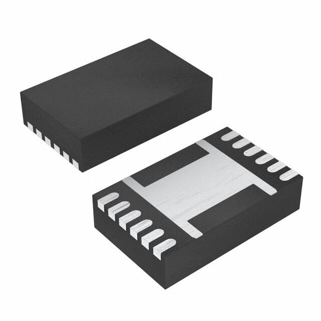


 工商网监
湘ICP备2023018690号
工商网监
湘ICP备2023018690号
