User's Guide
SLVU924D – March 2014 – Revised November 2018
bq76920 Evaluation Module User's Guide
The bq76920EVM evaluation module (EVM) is a complete evaluation system for the bq76920, a 3-cell to
5-cell Li-Ion battery analog front end (AFE) integrated circuit. The EVM consists of a bq76920 circuit
module which is used for simple evaluation of the bq76920 AFE and bq78350 gauge functions. The circuit
module includes one bq76920 integrated circuit (IC), sense resistor, power FETs, and all other onboard
components necessary to protect the cells from overcharge, over discharge, short circuit, and overcurrent
discharge in a 5-series cell Li-Ion or Li-Polymer battery pack. The circuit module connects directly across
the cells in a battery. With a compatible interface board and Microsoft® Windows® based PC graphical
user interface (GUI) software, the user can view the device registers, adjust protection limits and enable
FET control outputs.
1
2
3
4
5
6
7
8
Contents
Features ....................................................................................................................... 3
1.1
Kit Contents.......................................................................................................... 3
1.2
Ordering Information ............................................................................................... 3
1.3
bq76920 Circuit Module Performance Specification Summary ............................................... 3
1.4
Required Equipment ................................................................................................ 3
bq76920 EVM Quick Start Guide .......................................................................................... 4
2.1
Before You Begin ................................................................................................... 4
2.2
Quick Start ........................................................................................................... 4
Interface Adapter............................................................................................................. 8
bq76940/bq76930/bq76920 Software .................................................................................... 8
4.1
System Requirements .............................................................................................. 8
4.2
Installing the bq76940/bq76930/bq76920 Software ........................................................... 8
4.3
Interface Adapter.................................................................................................... 8
4.4
Software Operation ................................................................................................. 9
Battery Management Studio Software ................................................................................... 13
5.1
System Requirements ............................................................................................ 13
5.2
Installing bqStudio ................................................................................................. 14
5.3
Interface Adapter SMB ........................................................................................... 14
5.4
bqStudio Operation ............................................................................................... 14
5.5
Firmware Programming........................................................................................... 15
5.6
Data Memory Configuration ...................................................................................... 17
5.7
Chemistry View .................................................................................................... 18
5.8
Calibration ......................................................................................................... 19
5.9
Device Control ..................................................................................................... 21
bq76920 Circuit Module Use.............................................................................................. 21
6.1
Cell Simulator ...................................................................................................... 21
6.2
Evaluating with Simulated Current .............................................................................. 22
6.3
Reducing the Cell Count ......................................................................................... 22
6.4
Connecting Cells .................................................................................................. 23
6.5
Connecting to a Host ............................................................................................. 25
6.6
Gauge Circuits ..................................................................................................... 26
6.7
Unused Components ............................................................................................. 26
bq76920EVM Circuit Module Physical Construction................................................................... 28
7.1
Board Layout ....................................................................................................... 28
7.2
Bill of Materials .................................................................................................... 37
Related Documents From Texas Instruments .......................................................................... 43
SLVU924D – March 2014 – Revised November 2018
Submit Documentation Feedback
bq76920 Evaluation Module User's Guide
Copyright © 2014–2018, Texas Instruments Incorporated
1
�www.ti.com
List of Figures
1
EVM Connection for Basic AFE Operation ............................................................................... 5
2
EVM Connection for Basic Gauge Operation ............................................................................ 7
3
bq76940/bq76930/bq76920 Evaluation Software Display .............................................................. 9
4
Registers View .............................................................................................................. 10
5
I2C Pro View ................................................................................................................ 12
6
Sequence View ............................................................................................................. 12
7
Target Selection Wizard ................................................................................................... 14
8
bqStudio Window with Blank Gauge..................................................................................... 15
9
Firmware View .............................................................................................................. 16
10
Dashboard Adapter and Device Version Display ...................................................................... 16
11
Register View After Restart ............................................................................................... 17
12
Data Memory Bit Field change ........................................................................................... 18
13
Chemistry View ............................................................................................................. 19
14
Calibration View ............................................................................................................ 20
15
Example Voltage Calibration Successful ................................................................................ 20
16
Advanced Comm SMB View
17
18
19
20
21
22
23
24
25
26
27
28
29
30
31
.............................................................................................
Simulating Current Setup .................................................................................................
Example 3 Cell Simple Evaluation Configuration .....................................................................
Example Connection With 4 Cells .......................................................................................
Host Connection Concept .................................................................................................
Top Silk Screen.............................................................................................................
Top Assembly...............................................................................................................
Top Layer ...................................................................................................................
Layer 2 .......................................................................................................................
Layer 3 .......................................................................................................................
Bottom Layer................................................................................................................
Bottom Silk Screen .........................................................................................................
Bottom Assembly ...........................................................................................................
Schematic Diagram AFE ..................................................................................................
Schematic Diagram Gauge ..............................................................................................
Schematic Diagram Cell Simulator ......................................................................................
21
22
23
25
26
29
30
31
32
33
34
35
36
40
41
42
List of Tables
........................................................................................................
1
Ordering Information
2
Performance Specification Summary ..................................................................................... 3
3
3
Reducing Cell Count ....................................................................................................... 23
4
bq76920 Circuit Module Bill of Materials ................................................................................ 37
Trademarks
Microsoft, Windows are registered trademarks of Microsoft Corporation.
All other trademarks are the property of their respective owners.
2
bq76920 Evaluation Module User's Guide
SLVU924D – March 2014 – Revised November 2018
Submit Documentation Feedback
Copyright © 2014–2018, Texas Instruments Incorporated
�Features
www.ti.com
1
Features
•
•
•
•
•
•
1.1
Kit Contents
•
•
1.2
Complete evaluation system for the bq76920 3-cell to 5-cell Li-Ion and Phosphate battery AFE
Populated circuit module for 5-cell configuration for quick setup
Power connections available on banana jacks
Communication signals available on 4-pin connector
Resistor cell simulator for quick setup with only a power supply
PC software available for configuration
bq76920 circuit module
Cable to connect the EVM to an EV2400 or EV2300 interface board
Ordering Information
For complete ordering information, refer to the product folder at www.ti.com.
Table 1. Ordering Information
EVM Part Number
Chemistry
Configuration
Capacity
bq76920EVM
Li-Ion
5 cells
Any
NOTE: Although capacity is shown as Any, practical limits of the physical construction of the module
typically limits the operation of the EVM to a 1P or 2P battery construction. Refer to the
physical construction section for board details.
1.3
bq76920 Circuit Module Performance Specification Summary
This section summarizes the performance specifications of the bq76920 circuit module in its default 5-cell
series FET configuration.
Typical voltage depends on the number of cells configured. Typical current depends on the application.
Board cooling may be required for continuous operation at or below maximum current.
Table 2. Performance Specification Summary
Specification
Min
Typ
Max
Input voltage BATT+ with respect to BATT–
6
–
25
V
Continuous charge or discharge current
0
–
15
A
20
25
30
°C
Operating temperature range
1.4
Unit
Required Equipment
The following equipment is required to operate the bq76920 EVM in a simple demonstration:
• DC power supply, 0–25 V at 0.5 A for the AFE, 2.5 A for the gauge
• DC voltmeter
• TI EV2400 or EV2300 interface board
• Computer with USB port and compatible Windows operating system and access to the internet
• Test leads to connect equipment
• Electronic load or assorted resistors, calibrated load or load with accurate current meter required for
gauge evaluation
Additional equipment may be desired to operate the bq76920 with a more extensive demonstration.
SLVU924D – March 2014 – Revised November 2018
Submit Documentation Feedback
bq76920 Evaluation Module User's Guide
Copyright © 2014–2018, Texas Instruments Incorporated
3
�bq76920 EVM Quick Start Guide
www.ti.com
2
bq76920 EVM Quick Start Guide
2.1
Before You Begin
The following warnings and cautions are noted for the safety of anyone using or working close to the
bq76920 EVM. Observe all safety precautions.
Warning
The bq76920EVM circuit module may become hot during
operation due to dissipation of heat. Avoid contact with the
board. Follow all applicable safety procedures applicable to
your laboratory.
Caution
Do not leave the EVM powered when unattended.
!
CAUTION
The circuit module has signal traces, components, and component leads on the
bottom of the board. This may result in exposed voltages, hot surfaces or sharp
edges. Do not reach under the board during operation.
CAUTION
The circuit module may be damaged by over temperature. To avoid damage,
monitor the temperature during evaluation and provide cooling, as needed, for
your system environment.
CAUTION
Some power supplies can be damaged by application of external voltages. If
using more than 1 power supply, check your equipment requirements and use
blocking diodes or other isolation techniques, as needed, to prevent damage to
your equipment.
CAUTION
The communication interface is not isolated on the EVM. Be sure no ground
potential exists between the computer and the EVM. Also be aware that the
computer is referenced to the Battery- potential of the EVM.
2.2
Quick Start
Determine if you wish to evaluate the AFE alone or with the gauge. For the AFE, proceed to Section 2.2.1.
For the gauge, skip to Section 2.2.2.
2.2.1
AFE Quick Start
These steps describe quick connection of the bq76920 EVM to demonstrate operation of the AFE portion
of the EVM. For more detailed descriptions, refer to other sections of the user guide.
Refer to Figure 1 for the following steps.
1. Download the bq76940/bq76930/bq76920 Evaluation Software from the tool folder link
www.ti.com/tool/bq76920EVM or search from www.ti.com.
4
bq76920 Evaluation Module User's Guide
SLVU924D – March 2014 – Revised November 2018
Submit Documentation Feedback
Copyright © 2014–2018, Texas Instruments Incorporated
�bq76920 EVM Quick Start Guide
www.ti.com
2. Install the bq76940/bq76930/bq76920 evaluation software (see Section 4). Install drivers for the
EV2300, if necessary.
3. Remove shunts from headers connecting the AFE to the gauge.
4. If the EV2300 is used, install shunts on the SCL and SDA pull-up headers. Remove any pull-up shunts
when using the EV2400.
5. Close all dip switch positions (default is closed).
6. Attach the interface board communication adapter to the PC using USB cable. The EV2400 is
recommended, the EV2300 works if it is available and drivers are installed.
7. Attach the interface board I2C connector to the EVM I2C connector using the 4-pin cable.
8. Connect a 0-V DC power supply capable of 250 mA minimum to the “BATT” terminals and adjust to
approximately 18 V. The illuminated LED indicates the cell simulator resistor divider is powered.
9. Press and release the BOOT switch.
10. Start the bq769X0 evaluation software. The GUI should display. Click on the Scan box to enable
repeated update of the display. The power supply may be adjusted within range of the part to observe
voltage changes in the GUI display Stack V/T/I section.
11. Set the voltage to approximately 18 V or a mid-range operating level. Clear any faults present by
clicking on the Clear Faults button of the All Read/Write Registers section of the GUI.
12. Click on the Continuous button in the GUI Coulomb Counter section. Enable the CHG_ON and
DSG_ON bits by clicking on the bit and commit the changes. Apply a load to the PACK terminals. Load
current must be within the capability of the supply and the components installed or 15 A, whichever is
lower. Observe the Coulomb Counter value change in the GUI display Stack V/T/I section.
13. Make other adjustments as desired, for evaluation.
Refer to other sections of this user guide for additional details.
Pull-up
shunts,
Remove
for
EV2400
Install for
EV2300
I2C
SMB
USB
Remove gauge shunts
EV2400
DC Power Supply
Cell simulator switches
on for
power supply
Boot
switch
+ -
Figure 1. EVM Connection for Basic AFE Operation
SLVU924D – March 2014 – Revised November 2018
Submit Documentation Feedback
bq76920 Evaluation Module User's Guide
Copyright © 2014–2018, Texas Instruments Incorporated
5
�bq76920 EVM Quick Start Guide
2.2.2
www.ti.com
Gauge Quick Start
These steps describe quick connection of the bq76920 EVM to demonstrate operation of the gauge
portion of the EVM. For more detailed descriptions, refer to other sections of the user guide. If you are
new to bqStudio software, you may wish to refer to the more detailed instructions for installing the
software in Section 5 before using the quick start.
Refer to Figure 2 for the following steps.
1. Download the Battery Management Studio (bqStudio) software from the latest bq78350 product folder
link www.ti.com/product/bq78350-R1 or search from www.ti.com.
2. Install the bqStudio software. Install drivers for the EV2300, if necessary.
3. Install 4 shunts on the J12 header connecting the AFE to the gauge: GG_SCL, GG_SDA, GG_PWR
and GG_ALERT.
4. Install shunts on the SCL and SDA pull-up headers.
5. Install shunts on the /KEY, /PRES and 16/17 positions of the other headers.
6. Close all dip switch positions (default is closed).
7. Attach the interface board communication adapter to the PC using USB cable. The EV2400 version
0.18 or later may be used. Check the EV2400 tool folder for available updates. Do not use the original
0.05 version EV2400 since it may damage the EVM. The EV2300 works if it is available and drivers
are installed.
8. Attach the interface board SMB connector to the EVM SMB connector using the 4-pin cable.
9. Remove any connection to the I2C connector. This connector must remain open for operation with the
gauge.
10. Connect a 0-V DC power supply capable of 2 A minimum to the “BATT” terminals and adjust to
approximately 15 (3V/cell) V. The illuminated LED indicates the cell simulator resistor divider is
powered.
11. Press and release the BOOT switch.
12. Start the bqStudio software. The EVM has shipped with different versions of the bq78350 firmware.
Observe the windows which display as the software starts. If a Register View window appears similar
to Figure 11, check the gauge device version in the dashboard view on the left side of the window. If
the version is the latest, proceed to , otherwise perform the following steps. At this update bq78350-R1
is the production version, bq78350-R2 firmware is available.
a. The bq78350 on the initial EVMs shipped blank, so the bqStudio will present a Target Selection
Wizard box. Select the latest version of the bq78350 from the list and select the Finish button.
Acknowledge the Proceed and the Battery Management Studio Timeout windows. The GUI should
display similar to Figure 8.
b. If the gauge is not blank it will display the version in the dashboard similar to Figure 10. If the
version is correct proceed with evaluation.
c. Download the bq78350_xx firmware bundle from the latest bq78350 product folder such as
www.ti.com/product/bq78350-R1, save it to a temporary location on your computer, and run the
installer. Observe the installation directory of the firmware file, typically C:\ProgramData\Texas
Instruments\bq78350xxFirmwareBundle-xxxx
d. Click on the bqStudio Firmware button at the top of the window to select the firmware view.
e. Click on the Browse button right of the program window, navigate to and select the installed .srec
file.
f. Click on the Program button. Wait for the programming status window to close, typically about 45
s.
g. Restart the bqStudio software so it can autodetect the device.
13. In the registers view, select the Refresh button and observe that there are 3 cell voltages.
14. Change the cell count to the number of cells supported by the board: Select the Data Memory view,
then the Settings button and the AFE Cell Map register. Change the value to 0x001F and click on the
Write to Data Memory button. Read data memory if desired to confirm the new value.
15. Send a Reset command using the Commands view or the from the Advanced Comm SMB view.
6
bq76920 Evaluation Module User's Guide
SLVU924D – March 2014 – Revised November 2018
Submit Documentation Feedback
Copyright © 2014–2018, Texas Instruments Incorporated
�bq76920 EVM Quick Start Guide
www.ti.com
16. Select the Registers view and Refresh the values. Observe that all supported cells now show a
voltage reading.
17. Send the FET_EN command using the Commands view or the from the Advanced Comm SMB view.
18. Select the Registers view and Refresh the values. Observe that the FET_EN bit is now set and that
the CHG and DSG FET status is shown enabled.
19. Select the Calibration bq78350 view.
20. Enter the board temperature in the Temperature Sensor boxes and click on the Calibrate
Temperature button. Wait until a check box appears next to the button.
21. Measure the voltage of the BATT terminals. Divide the value by the number of cells and enter the
value in mV in the Ext Average Cell Voltage box. Click on the Calibrate Voltage button. Wait until a
check box appears next to the button.
22. Disconnect the load from the PACK terminals. Click on the Calibrate CC Offset button and wait until
the check mark appears next to the button.
23. Connect the load set to a known value of approximately 2 A to the PACK terminals. Enter the value in
mA into the Applied Current box. Discharge current should be entered as a negative value. Click on
the Calibrate Current button and wiat until the check mark appears next to the button.
24. Select the Registers view and Refresh the values. Observe the updated voltage, temperature and
current values.
The EVM is functioning and ready for further configuration for evaluation. Refer to the Technical
Reference Manual (TRM) or other documents for the bq78350, and the other sections of this user guide
for additional information.
I2C
SMB
USB
Install Gauge Shunts
Pull-ups
Required
EV2400
Cell Simulator Switches
on for
Power Supply
Boot
Switch
DC Power Supply
+ -
Electronic Load
+
-
Figure 2. EVM Connection for Basic Gauge Operation
SLVU924D – March 2014 – Revised November 2018
Submit Documentation Feedback
bq76920 Evaluation Module User's Guide
Copyright © 2014–2018, Texas Instruments Incorporated
7
�Interface Adapter
3
www.ti.com
Interface Adapter
The bq76940/bq76930/bq76920 evaluation software and bqStudio software support either the TI EV2400
or EV2300 interface board to provide communication with the EVM board from the computer. The EV2400
is the recommended interface and uses operating system drivers so no separate installation is required.
Drivers must be installed for the EV2300 and may not be available for newer operating systems. Do not
connect the EV2300 interface board to the computer until after the drivers are installed.
To use the EV2400 to program the bq78350, its firmware must be updated to version 0.18 or newer. The
firmware version of the EV2400 may be observed in the bqStudio dashboard, see Figure 10. Find the
latest EV2400 Firmware Updater in the tool folder http://www.ti.com/tool/ev2400.
If you have used an EV2300 with your computer previously, no additional installation is required. EV2300
drivers are included in the bq76940 software installation package and are found in the installation directory
after installing the software, typically at c:\Program Files (x86)\Texas Instruments\bq76940. Alternatively or
for the bqStudio software, drivers are found at
http://e2e.ti.com/support/power_management/battery_management/m/videos__files/458983.aspx or
http://www.ti.com/tool/ev2300. Install the drivers by following these steps:
1. Navigate to the directory with the drivers.
2. Run the file EV2300....exe file
4
bq76940/bq76930/bq76920 Software
This section describes how to install and use the bq76940/bq76930/bq76920 software for the EVM. This
software is used when evaluating the AFE alone without the gauge. For evaluation with the bq78350
gauge, refer to Section 5.
The bq76940/bq76930/bq76920 software supports the bq76920 AFE I2C communication. This software is
intended to demonstrate register control and operation of the bq769x0 family of AFEs in the absence of a
gauge or MCU. This software is not intended to operate on a bus with another master. The AFE does not
turn on the protection FETs without control, the bq76940/bq76930/bq76920 software provides that control
from the GUI.
The software may also be identified as bq76940 or bq769X0 in menus or windows as space permits.
4.1
System Requirements
The bq76940/bq76930/bq76920 software requires a Windows 7, or later operating system. The computer
must also have Microsoft® .NET connection software version 4.0, or higher, installed. The examples in this
document are from Windows 7.
4.2
Installing the bq76940/bq76930/bq76920 Software
Find the latest software version in the software section of the EVM tool folder
http://www.ti.com/tool/bq76920EVM or search from power.ti.com. Check periodically for software updates.
Use the following steps to install the bq76940/bq76930/bq76920 software:
1. Copy the archive file to a directory of your choice, extract all files and run the setup.exe application.
2. Follow the instructions and make selections as required on the setup windows selecting Next, as
required. TI recommends installing the software in the default location.
3. On the last window, select Close to complete the bq76940/bq76930/bq76920 software installation.
4.3
Interface Adapter
The interface adapter I2C connector should be connected to the I2C connector for use with the bq76940
software. Board pull-up shunts must be installed for the EV2300 and removed for the EV2400. The
interface adapter should not be connected to the I2C connector if a gauge or MCU is connected to the
bus.
8
bq76920 Evaluation Module User's Guide
SLVU924D – March 2014 – Revised November 2018
Submit Documentation Feedback
Copyright © 2014–2018, Texas Instruments Incorporated
�bq76940/bq76930/bq76920 Software
www.ti.com
4.4
Software Operation
This section describes connection of the communication interface to the EVM and operation of the
software.
Although the software runs without connection to a powered device, it is recommended to have the device
on when starting the software. Follow the directions in the quick start section. Figure 1 shows connections
for operation with the GUI software.
Start the software from the desktop shortcut bq769X0 Evaluation Software or the menu Start → All
Programs → Texas Instruments → bq769X0 Eval Software.
When started, the software looks for the communication interface and the device. If either is not found, a
popup window appears and must be acknowledged. When communication is established with the device,
the main window appears as shown in Figure 3.
The bq76940/bq76930/bq76920 software uses popup help tips on many of the control features.
Figure 3. bq76940/bq76930/bq76920 Evaluation Software Display
The software window contains a menu bar and 3 sections. The top section is an I2C tool. The middle
section has 3 selectable views. The bottom section is a status section. Details are described in following
sections.
4.4.1
Status Section
The bottom section displays the software name and version, the CRC mode and the communication
status. The CRC mode is automatically detected and the software communicates to the IC appropriately.
To the right of the CRC mode is a communication status area which may display information about the
communication with the device. Common displays and actions may include the following:
• Data channel name is invalid. Check the USB connection to the interface board. Exit and restart the
software
• No acknowledge from device. Check that the 4 pin cable is connected, the EVM is powered and boot
the device, then try to read the device.
• CRC read from device does not match calculated CRC. Check that the Read Device button was used
SLVU924D – March 2014 – Revised November 2018
Submit Documentation Feedback
bq76920 Evaluation Module User's Guide
Copyright © 2014–2018, Texas Instruments Incorporated
9
�bq76940/bq76930/bq76920 Software
•
•
•
4.4.2
www.ti.com
to detect the device. Check the connection of the 4 pin cable or its routing near high noise sources.
Not able to find a free communication adapter. Check the connection of the USB cable to the
communication adapter.
USB adapter timeout. Unplug and re-connect the USB cable and try to read from the device again.
When the status area is blank, the last communication with the device was successful
I2C Section
The top section of the window below the menu bar has the I2C address and a byte communication tool.
The I2C address must be entered, the tool does not automatically detect the address. The default address
is 0x08 which is the default address for the device on the EVM. If the AFE on the EVM has been changed
to a different address, the address must be entered. The value is the 7 bit address and is shifted left 1 bit
position when observed on the bus.
The byte communication tool is useful to read or write a register. It is present with all views.
4.4.3
Menu Commands
The Help > About menu selection displays version information about the program. Other selections may
provide additional help or links to documentation.
The Options > Verify Writes selection allows selection of a readback of the registers once they are written.
The View menu allows selection of the center window display. Options are the Registers, I2C Pro or
Sequence views. Views can also be selected with buttons on the left side of the window.
Exit the program with the File menu.
4.4.4
Registers View
The registers view is the default display in the middle of the window when the software is started, see
Figure 4. It shows the control register values. If another view is displayed it is selected using the
Registers button on the left side of the window or from the menu.
Figure 4. Registers View
10
bq76920 Evaluation Module User's Guide
SLVU924D – March 2014 – Revised November 2018
Submit Documentation Feedback
Copyright © 2014–2018, Texas Instruments Incorporated
�bq76940/bq76930/bq76920 Software
www.ti.com
The Read Device button at the top of the Registers view provides important setup of the
bq76940/bq76930/bq76920 software and the IC. The software reads the factory gain and offset data from
the device and populates these in the Stack V/T/I section for use in calculating display values. The
software writes the CC_CFG register to its proper value and also detects the CRC mode of the device and
sets the software appropriately.
The control registers are shown in the center of the display in the All Read/Write Registers section. Bits
are color coded as described in the section. Bits may be changed by clicking on the bit and selecting
Commit button in the Change value pop-up window. The default for the pop up window is to change the
polarity of the bit. Since clearing status bits requires a write of 1, the Set bit high needs to be checked in
the Change value pop-up window when clearing status register bits. A bit value change is displayed if the
Options menu Verify Writes is selected.
Control registers can also be changed as register values by writing in the value box to the right of the
value box. Scan must be disabled to enter values. Register values may also be changed using the I2C
byte write tool at the top of the window. Register changes are visible if the Verify Writes option is enabled.
The display may also be updated using the Update Display button or selecting Scan.
The All Read/Write Registers section contains 4 buttons to the right of the register display:
• Update Display: This button reads all control and value registers and updates the values, bit breakout
fields and control features.
• Clear Faults: This button clears the status register.
• Save Configuration: This button allows saving the displayed values of the control register to a file. A
pop-up box allows selection of the file name. The default file location is C:\Users\\Documents\Texas Instruments\bq76940.
• Load configuration: This button allows loading the control register values from a file. A pop-up box
allows selection of the file, another pop up box lets you select whether to write the values to the
device. If faults are not set in the status register value in the file, they are not cleared by the write.
The Base Configuration section shown above the register detail provides convenient control of the
Coulomb Counter, ADC and Temperature Sensor selection as functional controls without locating the
control bits.
The Data Scanning section allows periodic read of the device and display of the register values. The Scan
check box enables the read when checked. The update interval is displayed and can be changed with the
Change Interval button.
The Logging section has the Start Logging button. The values read from the device can be saved to a
file. Selecting the Start Logging button opens a bq76940 Logging popup window to enter the file name,
comments and to select the data groups to be logged. The file name must be entered with the pop up
window's Browse button. The scan interval can be changed, and the logging is actually started in the pop
up window. When logging is active, the registers user interface cannot be used and the button changes to
Stop Logging. Selecting the button stops the logging. Scan is not necessary before logging, it will start
with logging and cannot be disabled during logging.
The Stack V/T/I section is on the right side of the Registers view (Figure 4). The ADC Gain and Offset
boxes show the values that are used for converting the register data into values. These value boxes are
read only, they are updated by the values read from the device with the Read Device button. The Display
raw data read from device below check box allows display of the hex register values rather than converted
values. The V/T/I values are updated by the Read Device button, the Update Display button, or the Scan
option.
4.4.5
I2C Pro View
Figure 5 shows the I2C Pro view of the GUI. The I2C Pro view is useful to read or write several sequential
registers. If another view is displayed, it can be selected using the I2C PRO button on the left side of the
window or from the menu. The I2C Command box for each section specifies the starting register address
for the transaction.
SLVU924D – March 2014 – Revised November 2018
Submit Documentation Feedback
bq76920 Evaluation Module User's Guide
Copyright © 2014–2018, Texas Instruments Incorporated
11
�bq76940/bq76930/bq76920 Software
www.ti.com
Figure 5. I2C Pro View
4.4.6
Sequence View
Figure 6 illustrates the Sequence view of the GUI. This is useful to send timed sequences of register
reads or writes to the device. It can be selected using the SEQUENCE button on the left side of the
window or from the menu. A sequence is run by selecting its Execute button. The results of the sequence
are shown in the Sequence Dialog section. Edit the sequence by selecting the file name under the
sequence name in the window.
Figure 6. Sequence View
12
bq76920 Evaluation Module User's Guide
SLVU924D – March 2014 – Revised November 2018
Submit Documentation Feedback
Copyright © 2014–2018, Texas Instruments Incorporated
�Battery Management Studio Software
www.ti.com
The installation comes with 3 sequence files. The Clear Faults files contain descriptions for requirements
for a sequence file. The Set UV Trip... file shows an example of a simpler format. Sequence files are
installed to: C:\Users\\Documents\Texas Instruments\bq76940\sequence. Sequences are
loaded from this location when the program starts. Create new sequences with a text editor and save
them with the .bqseq extension. Up to 8 sequences can be stored, move other sequences to another
directory or change the extension. The sequences Sequence_Example.bqseq, Sequence Clear
Faults.bqseq, and UVTrip.bqseq are required, do not move them from the directory.
Typical uses of a sequence might include:
• Reading and clearing faults, then enabling CHG and DSG outputs
• Setting ship mode
• Setting a balance pattern
• Any repetitive multiple-register write used in evaluation
While sequences can be executed during logging, the logging is paused while the sequence executes.
Long sequences leave gaps in the log data.
4.4.7
Typical Operation of Software
Typical operation of the software involves the following steps, much like described in quick start section:
• Connect the EVM and related equipment
• Power the EVM
• Boot the EVM
• Start the software
• Read and change registers, as desired
If
•
•
•
•
the board is powered off during the evaluation process:
Power the EVM
Boot the EVM
Select the Read Device button
Read and change registers, as desired
If the interface board is connected to a system already in operation and the software has not been exited:
• Select the Read Device button
• Read and change registers, as desired
4.4.8
Operation with Other Interfaces or Hosts
The bq76940/bq76930/bq76920 software does not support other interface boards or adapters other than
the EV2300 and EV2400. The software does not operate in a multi-master environment. If operated with
another host on the line, data collisions can occur. Also be aware that the EV2400 has internal pull-up
resistors to 3.3 V, connecting to some shared busses could damage devices on that bus if the bus voltage
differs.
5
Battery Management Studio Software
The Battery Management Studio software is used for evaluation of the bq78350 gauge. It is also identified
as bqStudio for a compact name. If an earlier version of the bqStudio software is already installed from
another product evaluation, it should still be installed again to load the configuration files and tools specific
to the current version of the bq78350.
5.1
System Requirements
The bqStudio software requires a Windows 7, or later, operating system. Additional items are required and
are described in the installation windows. The examples in this document are from Windows 7.
SLVU924D – March 2014 – Revised November 2018
Submit Documentation Feedback
bq76920 Evaluation Module User's Guide
Copyright © 2014–2018, Texas Instruments Incorporated
13
�Battery Management Studio Software
5.2
www.ti.com
Installing bqStudio
Find the latest software version in the tool folder http://www.ti.com/tool/bqstudio or search from
power.ti.com. Check periodically for software updates. Use the following steps to install the bqStudio
software:
1. Copy the archive file to a directory of your choice, extract all files and run the Battery Management
Studio-xxxxxx-Setup.exe application.
2. Follow the instructions and make selections as required on the setup windows selecting Next, as
required. TI recommends installing the software in the default location.
3. On the last window, select Finish to complete the bqStudio software installation.
5.3
Interface Adapter SMB
The interface adapter SMB connector must be connected to the SMB connector of the EVM for use with
the bqStudio software. Pull-ups for the SMBus are provided inside the adapter. The interface adapter
should not be connected to the I2C connector of the EVM.
5.4
bqStudio Operation
bqStudio is used to communicate to the bq78350 gauge for evaluation. It includes a number of tools to aid
in configuration of the bq78350 for evaluation. bqStudio will not communicate with the AFE and the I2C
connector of the EVM should not be connected while using bqStudio.
Although the software runs without connection to an interface board or powered device, it is
recommended to have both connected and the device on when starting the software. Follow the directions
in the Gauge Quick Start section. Figure 2 shows connections for operation with the bqStudio software.
Start the software from the desktop shortcut Battery Management Studio or the menu Start → All
Programs → Texas Instruments → Battery Management Studio.
When started, the software looks for the communication interface and the device. If the device is found,
the registers will display such as in Figure 11. If the version is up to date the user may choose to proceed
to other evaluation steps. If the device is not found, it opens a Target Selection Wizard. This is expected
for a new EVM since the bq78350 is not programmed. Select the newest bq78350 version in the list and
click the Finish button. This selection will be remembered until the software is re-stared. If the device is
not found, the user will be presented with a Proceed? window which must be acknowledged. If the
software still can not find the device, a Battery Management Studio popup window appears indicating
communication status. With a blank or un-powered part, this will indicate a timeout. Acknowledge the
message to proceed.
Figure 7. Target Selection Wizard
14
bq76920 Evaluation Module User's Guide
SLVU924D – March 2014 – Revised November 2018
Submit Documentation Feedback
Copyright © 2014–2018, Texas Instruments Incorporated
�Battery Management Studio Software
www.ti.com
If the software was started without a communication interface adapter, a Battery Management Studio
popup window will indicate a free adapter is not available. Acknowledge the message to proceed. Errors
will appear in the left bottom border of the Battery Management Studio screen. Correct the problem with
the adapter and restart the software.
When the software is first started in a new installation, a welcome view covers the main portion of the
window. This offers an overview or tutorials of the software. After reviewing any desired content, close the
welcome view. If it is desired to see this again, the welcome view can be opened from the menu selection
Help | Welcome.
bqStudio contains a user guide for general operation of the software. Refer to the menu selection Help |
Help Contents for information.
Once the welcome view is closed, the bqStudio window appears as shown in Figure 8. For a blank gauge
the register area is blank since communication with the blank device on the EVM does not provide data.
Figure 8. bqStudio Window with Blank Gauge
5.5
Firmware Programming
If the gauge is blank or an update is needed, firmware must be programmed to the bq78350 mounted to
the EVM before operation. EV2400 versions before 0.18 should not be used to program firmware.
Firmware is programmed using the Firmware view shown in Figure 9. Click on the Browse button and
select the file to be programmed. Using the Execute after programming feature is recommended. Click on
the Program button to start programming. A Progress Information window will display during programming
and will close when complete. Programming typically takes about 45 s.
SLVU924D – March 2014 – Revised November 2018
Submit Documentation Feedback
bq76920 Evaluation Module User's Guide
Copyright © 2014–2018, Texas Instruments Incorporated
15
�Battery Management Studio Software
www.ti.com
Figure 9. Firmware View
After programming, restart the bqStudio software so that it will autodetect the new firmware and load the
proper configuration for the tools. After start with autodetection, the dashboard display should show the
version read from the device rather than a version input from the Target Selection Wizard. An example of
the dashboard display is shown in Figure 10. If the version read by the autodetect is the same as the
version previously selected in the Target Selection Wizard, no change may be apparent, but restarting to
allow tool configuration is still recommended.
Figure 10. Dashboard Adapter and Device Version Display
The default configuration of the firmware is for 3 cells. An example of the register view after restart is
shown in Figure 11. Note that 3 cell voltages are present. The device must be configured for operation
with other cell counts, this includes basic operation of the EVM.
16
bq76920 Evaluation Module User's Guide
SLVU924D – March 2014 – Revised November 2018
Submit Documentation Feedback
Copyright © 2014–2018, Texas Instruments Incorporated
�Battery Management Studio Software
www.ti.com
Figure 11. Register View After Restart
5.6
Data Memory Configuration
Most of the configuration of the bq78350 is accomplished through setting values in data memory. The data
memory is accessed using the Data Memory view. Configuration values are orgainized in functional
groups selected by buttons on the left side of the view. Data values may be changed by selecting and
entering a value. Parameter registers which are bit fields may be changed by selecting the bit in the pop
up when the register or its value is selected. Figure 12 shows the bit field for the AFE Cell Map which is
one of the most basic settings that must typically be changed with the EVM. The AFE Cell Map is a
physical location of the cells. Refer to the bq78350-R1 TRM (SLUUBD3) for information on this and other
configuration parameters. Data Memory must be written after change. See other technical documents in
the bq78350 product folder www.ti.com/product/bq78350-R1.
The Export tool in the Data Memory view allows saving the configuration data to a comma-separatedvalue file format which can be accessed by a spreadsheet program. Reading data before export will save
the data from the part rather than values which may be only in the view. The Import tool allows loading
such a file into the view so that it can be written to the device.
SLVU924D – March 2014 – Revised November 2018
Submit Documentation Feedback
bq76920 Evaluation Module User's Guide
Copyright © 2014–2018, Texas Instruments Incorporated
17
�Battery Management Studio Software
www.ti.com
Figure 12. Data Memory Bit Field change
5.7
Chemistry View
The bq78350 uses the chemistry of the cells to estimate the state of charge of the pack after a reset.
Chemistry information is not loaded to the device as a Data Memory parameter but by using the Chemistry
view. Loading the chemistry is not required for simple operation of the EVM but will be desired for setup of
the board or a part for operation with cells, particularly if the chemistry differs from the default. The
chemistry view is shown in Figure 13.
18
bq76920 Evaluation Module User's Guide
SLVU924D – March 2014 – Revised November 2018
Submit Documentation Feedback
Copyright © 2014–2018, Texas Instruments Incorporated
�Battery Management Studio Software
www.ti.com
Figure 13. Chemistry View
5.8
Calibration
The EVM and all new boards should be calibrated before operation. The calibration view is shown in
Figure 14. Temperature is typically calibrated first. Current Offset should be calibrated with no current flow
and should be calibrated before Current Gain. The EVM uses a 1-mΩ sense resistor and calibration at low
current will result in some granularity from the current resolution. This may result in an apparent error at
higher currents. Calibration at higher currents will reduce this effect and should be done where it is
important.
By default, the bq78350 uses the average cell voltage for gauging. This voltage must be calibrated.
Measure the battery voltage, calculate the average cell value and enter the value in the box. Clicking the
Calibrate Voltage button runs the calibration. Values left blank or entered as '0' are not calibrated. When
successful, a green check appears next to the button as shown in Figure 15. If there is an error, a red X
appears instead with a message. The bq769x0 contains factory voltage calibration data for cell voltage
values. The bq78350 uses this data to determine the individual cell voltage. When it is desired to calibrate
each cell's offset rather than relying on the average stored in the bq769x0, individual cell voltages can be
measured and calibrated. Cells can be calibrated in groups or individually by entering or clearing the
desired values.
Basic steps for calibration of the EVM is described in the quick start section. Since the EVM uses 1%
values for the cell simulator resistors, measuring each cell voltage value is recommended rather than
using a common value if individual cell voltage calibration is desired.
SLVU924D – March 2014 – Revised November 2018
Submit Documentation Feedback
bq76920 Evaluation Module User's Guide
Copyright © 2014–2018, Texas Instruments Incorporated
19
�Battery Management Studio Software
www.ti.com
Figure 14. Calibration View
Figure 15. Example Voltage Calibration Successful
20
bq76920 Evaluation Module User's Guide
SLVU924D – March 2014 – Revised November 2018
Submit Documentation Feedback
Copyright © 2014–2018, Texas Instruments Incorporated
�Battery Management Studio Software
www.ti.com
5.9
Device Control
Features are controlled by commands as described in the bq78350-R1 TRM (SLUUBD3). One of the most
basic for operation as described in the quick start section is the FET enable which is toggled by the
ManufacturerAccess() 0x0022 command. The Manufacturer Access commands may be sent using the
Advanced Comm SMB view and the Write Word button. An example is shown in Figure 16. A number of
the common commands are also available in buttons in the Commands view. Using the commands the
gauge may be controlled for test or setup for further evaluation. Refer to the bq78350-R1 TRM for
additional information on the commands.
Figure 16. Advanced Comm SMB View
6
bq76920 Circuit Module Use
The bq76920 circuit module contains the bq76920 IC and related circuitry to demonstrate the features of
the IC. Surface mount FETs are provided for the high current path. A thermistor provides temperature
sensing on the board. Other components provide support for the IC and connections to the board. Basic
operation is described in the quick start guide. For details of the circuit, refer to the physical construction
section.
6.1
Cell Simulator
The EVM includes a resistive cell simulator made up of 200-Ω series resistors. The top section of the S3
switch connects the BATT+ node to the top of the resistor string. The bottom of the resistor string is
connected to BATT–. The individual cell taps are connected to the cell monitor signals by other sections of
the dip switch. When operating with a power supply all switch sections should be closed. When operating
with cells, all the dip switch sections should be open to prevent loading the cells and discharging the
battery. The cell simulator resistors are located on the bottom of the board and may become warm during
operation. The orange LED near the dip switch indicates the cell simulator has power either from the
BATT+ or cell inputs.
SLVU924D – March 2014 – Revised November 2018
Submit Documentation Feedback
bq76920 Evaluation Module User's Guide
Copyright © 2014–2018, Texas Instruments Incorporated
21
�bq76920 Circuit Module Use
6.2
www.ti.com
Evaluating with Simulated Current
I2C
SMB
USB
The quick start guide describes connection for basic operation. Providing more than recognizable current
in that configuration can require a power supply with a significant power rating. Applying a charge current
can damage some power supplies. Figure 17 shows a method to force current through the control path
without a high wattage power supply or special equipment. The load power supply should be set at a low
voltage in a constant current mode. Polarity can be reversed on the load supply to simulate a charge
current. The battery simulation supply should never be reversed. The diagram shows communication
connection for AFE evaluation, the technique will also work for gauge evaluation with appropriate
communication connection.
EV2400
DC Power Supply
+ -
DC Power Supply
(Load)
+ -
Figure 17. Simulating Current Setup
The power supply technique can also be used with the bq78350 to provide current for calibration or to
show current flow. However the simulated current will not provide good gauging evaluation.
6.3
Reducing the Cell Count
Cell count can be reduced for basic evaluation by shorting unused cells at the input terminal block. Follow
the recommendations in the datasheet for which cells to short. This works for both operation with the cell
simulator and cells, but can have some side effects in transient tests because it parallels the shorted
resistors to the cell IC where the capacitor provides a signal path to the used input. See Figure 18 for an
example of simple reduced cell configuration for 3 cells. For the best evaluation with reduced cells in a
transient environment, short the VCx pins at the capacitor or VCx test points and remove the unused input
resistor. When using the cell simulator, shorting the unused cell resistor is still required to eliminate the
simulated cell voltage. Shorting the cell inputs at the terminal block screw terminals is suggested since it
should be apparent if the board is re-used for a different cell count. Table 3 shows configuration
recommendations for reduced cell count.
22
bq76920 Evaluation Module User's Guide
SLVU924D – March 2014 – Revised November 2018
Submit Documentation Feedback
Copyright © 2014–2018, Texas Instruments Incorporated
�bq76920 Circuit Module Use
www.ti.com
Table 3. Reducing Cell Count
Unused Cell
(Numbered from Bottom Cell 1)
Short Cell Terminals
Input Resistor to Remove
Short AFE Inputs
Cell 4
C4 to C3
R5
VC4 to VC3
Cell 3
C3 to C2
R6
VC3 to VC2
When evaluating the gauge, it is recommended to reduce the cell count of the gauge configuration before
connecting the cells. If the gauge does not see voltage it will shut down the AFE and require re-boot of the
board. To avoid shutdown simulate a charge current until the cell count configuration can be corrected.
See table for
reduced cell
configuration
3 cells shown
Short C4 to C3
and C3 to C2
Simple evaluation,
allows easy cell
count change but
leaves parallel paths
to IC
Cell simulator switches on
DC Power Supply
+ -
Figure 18. Example 3 Cell Simple Evaluation Configuration
6.4
Connecting Cells
The EVM is constructed to sense the cell voltages at the cells. Separate wires are required from the
bottom of the battery stack to the C0 connection at the terminal block for sensing voltage and from the
bottom of the battery stack to the BATT– terminal to carry the load current. The AFE IC VSS is referenced
to the BATT– connection. Similarly, separate wires are required from the top of the battery stack to the top
cell input of the terminal block and from the top of the battery stack to the BATT+ terminal to carry the
load current. The top cell sense connection also powers the AFE IC. To move the sense connections from
the cells to the board, populate R1 and R2. The bottom cell simulator switch can be closed to connect C0
to BATT–.
SLVU924D – March 2014 – Revised November 2018
Submit Documentation Feedback
bq76920 Evaluation Module User's Guide
Copyright © 2014–2018, Texas Instruments Incorporated
23
�bq76920 Circuit Module Use
www.ti.com
The cell simulator provides resistors between the cell inputs. These resistors can help divide the voltage
as cells are connected. If desired, the cell simulator switches can be closed during cell connection and
opened after cell connection. The switches must be opened after connection of cells or the cells will be
discharged by the constant drain of the cell simulator. If the orange LED is on when cells are connected,
open the dip switch sections to remove the load.
Cell connection is generally considered safest from the bottom up. This minimizes the step size of the
voltage applied to the board. Recommended connection sequence for the EVM when connecting wires
individually is bottom up:
1. Connect BATT–
2. Connect cells bottom up; C0, C1, C2 ...
3. Connect BATT+
4. Open the cell simulator switches, if needed
When the top and bottom cells are connected on the board:
1. Connect BATT– (includes C0)
2. Connect cells bottom up; C1, C2, C3...
3. Connect BATT+ (includes top cell)
4. Open the cell simulator switches, if needed
When cells are mated with a connector:
1. Connect BATT– or the node which connects VSS of the AFE, if separate
2. Mate the connector
3. Connect the BATT+. if separate
4. Open the cell simulator switches, if needed
Figure 19 shows an example connecting cells with an EVM configuration reduced to 4 cells.
24
bq76920 Evaluation Module User's Guide
SLVU924D – March 2014 – Revised November 2018
Submit Documentation Feedback
Copyright © 2014–2018, Texas Instruments Incorporated
�bq76920 Circuit Module Use
www.ti.com
See table for reduced cell configuration
4 cells shown
Short VC4 to VC3
Remove R5
Short C4 to C3
(optional with cells and R5 removed)
With cells, open switches to avoid
draining cells
If connecting cells confirm operation
before connecting. Use all appropriate
fusing, insulation, isolation and shielding
necessary for safe operation. Board has
exposed contacts. Do not leave
unattended
Figure 19. Example Connection With 4 Cells
When using external balancing with P-channel MOSFETs, such as on the bq76930 and bq76940 EVMs,
the inrush current for a cell can momentarily turn on the balance FET causing the next cell input below to
rise. This can continue down the stack. Connecting C0 on the board by closing the C0 dip switch during
cell connection can reduce stress on the VC0 input of the AFE. Open the switch after cell connection for
sensing at the cell.
6.5
Connecting to a Host
After initial operation of the AFE with the bq76940/bq76930/bq76920 software, it may be desirable to
operate the board connected to a microcontroller board. J12 could be used to connect to the
microcontroller board. No voltages should be applied to the gauge terminals. Alternately, the
microcontroller is connected to the signal test points or J8 and the ALERT test point. The bq76920
installed on the EVM is a 2.5V ouput device. Be sure the MCU will operate at 2.5V or provide separate
power for the MCU and shift the level of the interface signals if needed. Pull-ups may not be required on
the EVM if they are provided on the MCU. Although it was developed for 10 cells, TIDA-00449 implements
an example host for the bq76930 family member of the AFE using the MSP430. The code is available for
the TI Design and may be a helpful reference in development of a host system.
SLVU924D – March 2014 – Revised November 2018
Submit Documentation Feedback
bq76920 Evaluation Module User's Guide
Copyright © 2014–2018, Texas Instruments Incorporated
25
�bq76920 Circuit Module Use
www.ti.com
Remove gauge shunts,
Wire to MCU board
MCU
evaluation
board
DC Power Supply
Pull-ups if
required
Cell simulator switches
on for
power supply
Boot
switch
+ -
Figure 20. Host Connection Concept
6.6
Gauge Circuits
The EVM contains a gauge circuit consisting of U2 and an SMBus interface connector, J14. This bq78350
IC and circuit can be used to control the AFE if configured and connected at the J12 header. By default
the AFE on the EVM is a 2.5-V output device, only connect the gauge circuitry to a 2.5-V output AFE IC.
Shunts may be placed on the /KEY and /PRES headers to simulate control of these signals. An alternate
SMBus address may be selected using the SMBus header. Refer to the bq78350-R1 TRM for details and
configuration selections for these device features.
Basic operation of the gauge is shown in Section 2.2.2, for more details on operation see the bq78350-R1
TRM.
6.7
Unused Components
The EVM contains a number of component patterns which may be useful for evaluation.
Test points are not typically populated. The patterns may be used as probe points or wires or test points
could be soldered to provide probing, if desired.
Normally the power filter R14 and C13 keeps the supply voltage for the AFE in a safe operating range. For
situations with large transients, D3 provides a clamp for the supply voltage to the AFE, if needed. The
pattern is large and it is easy to fit other component sizes. Be aware that if the system transients are large
enough that a clamp is needed at D3, the cell inputs should also be inspected for excessive voltages and
an improved filter or clamp be added there, if needed.
The ALERT line switches high and low in normal operation as status bits are asserted and cleared. A
large load is not desired since it consumes power. If it is useful to slow the transition, the pattern C10 is
available. C10 should not be large in order to avoid current and slowing the edge to where the bq76920
would see the ALERT high as an input and set the OVRD_ALERT condition.
When the charge FET turns on with a large charger voltage present, a large voltage could be impressed
on the gate of the charge FET. With the voltages typically used on the bq76920EVM, this should not be
high enough to damage the charge FET. If special circumstances require, the D5 pattern is available for a
clamp diode.
26
bq76920 Evaluation Module User's Guide
SLVU924D – March 2014 – Revised November 2018
Submit Documentation Feedback
Copyright © 2014–2018, Texas Instruments Incorporated
�bq76920 Circuit Module Use
www.ti.com
D6 is a flyback diode to prevent PACK- from rising significantly above PACK+. The D7 pattern provides a
place to mount a higher current diode or other transient suppression component.
HS1 is a position to mount a suitable heatsink, if needed. Other heatsink options may be available in the
evaluation environment.
R34 and R35 provide options to pull down unused signals. Connect as recommended in the datasheet for
the bq78350 used.
J11, C19, R28, R29, R33, R40, R41, R42, and R56 provide component patterns to optinally bring signals
to a convenient location for evaluating the behavior of the bq78350 with a high side switch configuration.
SLVU924D – March 2014 – Revised November 2018
Submit Documentation Feedback
bq76920 Evaluation Module User's Guide
Copyright © 2014–2018, Texas Instruments Incorporated
27
�bq76920EVM Circuit Module Physical Construction
7
www.ti.com
bq76920EVM Circuit Module Physical Construction
This section contains the PCB layout, bill of materials, and schematic of the bq76920EVM circuit module.
The bq76920EVM consists of one circuit module assembly, PWR523.
7.1
Board Layout
The bq76920EVM circuit module is a 4.0-inch × 4.805-inch 4-layer circuit card assembly. It is designed for
easy assembly with cell connections on the left side to a terminal block and high current terminals through
banana jacks. Control connections are on the left top. Pack terminals are on the right side using banana
jacks. Wide trace areas are used reducing voltage drops on the high current paths. The EVM layout and
construction allows easy understanding of the connections and access to the test points for evaluation, but
the connector area and programming features result in a large board.
The board layout includes spark gaps with the reference designator prefix "E". These spark gaps are
fabricated with the board and no component is installed. The design includes spark gap E1 across the
power FETs. Contamination on the board or shorting of the pattern could bypass the power FETs and E1
is not recommended.
See additional information in the configuration and operation sections of this document. Figure 21 to
Figure 28 show the board layout.
28
bq76920 Evaluation Module User's Guide
SLVU924D – March 2014 – Revised November 2018
Submit Documentation Feedback
Copyright © 2014–2018, Texas Instruments Incorporated
�bq76920EVM Circuit Module Physical Construction
www.ti.com
Figure 21. Top Silk Screen
SLVU924D – March 2014 – Revised November 2018
Submit Documentation Feedback
bq76920 Evaluation Module User's Guide
Copyright © 2014–2018, Texas Instruments Incorporated
29
�bq76920EVM Circuit Module Physical Construction
www.ti.com
Figure 22. Top Assembly
30
bq76920 Evaluation Module User's Guide
SLVU924D – March 2014 – Revised November 2018
Submit Documentation Feedback
Copyright © 2014–2018, Texas Instruments Incorporated
�bq76920EVM Circuit Module Physical Construction
www.ti.com
Figure 23. Top Layer
SLVU924D – March 2014 – Revised November 2018
Submit Documentation Feedback
bq76920 Evaluation Module User's Guide
Copyright © 2014–2018, Texas Instruments Incorporated
31
�bq76920EVM Circuit Module Physical Construction
www.ti.com
Figure 24. Layer 2
32
bq76920 Evaluation Module User's Guide
SLVU924D – March 2014 – Revised November 2018
Submit Documentation Feedback
Copyright © 2014–2018, Texas Instruments Incorporated
�bq76920EVM Circuit Module Physical Construction
www.ti.com
Figure 25. Layer 3
SLVU924D – March 2014 – Revised November 2018
Submit Documentation Feedback
bq76920 Evaluation Module User's Guide
Copyright © 2014–2018, Texas Instruments Incorporated
33
�bq76920EVM Circuit Module Physical Construction
www.ti.com
Figure 26. Bottom Layer
34
bq76920 Evaluation Module User's Guide
SLVU924D – March 2014 – Revised November 2018
Submit Documentation Feedback
Copyright © 2014–2018, Texas Instruments Incorporated
�bq76920EVM Circuit Module Physical Construction
www.ti.com
Figure 27. Bottom Silk Screen
SLVU924D – March 2014 – Revised November 2018
Submit Documentation Feedback
bq76920 Evaluation Module User's Guide
Copyright © 2014–2018, Texas Instruments Incorporated
35
�bq76920EVM Circuit Module Physical Construction
www.ti.com
Figure 28. Bottom Assembly
36
bq76920 Evaluation Module User's Guide
SLVU924D – March 2014 – Revised November 2018
Submit Documentation Feedback
Copyright © 2014–2018, Texas Instruments Incorporated
�bq76920EVM Circuit Module Physical Construction
www.ti.com
7.2
Bill of Materials
The bill of materials for the circuit module is shown in Table 4. Substitute parts may be used in the manufacturing of the assembly.
Table 4. bq76920 Circuit Module Bill of Materials
Designator
Qty
Value
Description
Package Reference
Part Number
MFG
Alternate
Part Number
Alternate
MFG
PCB1
1
C1, C2, C3, C4, C5, C6, C14
7
1uF
CAP, CERM, 1uF, 16V, +/-10%, X7R, 0805
0805
PWR523
Any
-
-
GRM21BR71C105KA01L
MuRata
C7, C8, C9, C11, C12, C17, C18,
C21, C22, C23
10
0.1uF
CAP, CERM, 0.1uF, 50V, +/-10%, X7R, 0603
0603
GCM188R71H104KA57B
MuRata
C13
1
2.2uF
C15
1
4700pF
CAP, CERM, 2.2uF, 50V, +/-10%, X5R, 1206
1206
GRM31CR61H225KA88L
MuRata
CAP, CERM, 4700pF, 50V, +/-10%, X7R, 0805
0805
08055C472KAT2A
C16
1
AVX
4.7uF
CAP, CERM, 4.7uF, 10V, +/-10%, X7R, 0805
0805
GRM21BR71A475KA73L
C20
MuRata
1
3300pF
CAP, CERM, 3300pF, 25V, +/-10%, X7R, 0603
0603
GRM188R71E332KA01D
MuRata
D1
1
28V
Diode, TVS, Uni, 28V, 1500W, SMC
SMC
SMCJ28A
Fairchild Semiconductor
D2, D4, D12
3
1.25V
Diode, Ultrafast, 100V, 0.15A, SOD-123
SOD-123
1N4148W-7-F
Diodes Inc.
D6
1
600V
Diode, Ultrafast, 600V, 3A, SMC
SMC
MURS360T3G
ON Semiconductor
D8, D9, D10, D11, D19, D20
6
5.6V
Diode, Zener, 5.6V, 200mW, SOD-323
SOD-323
MMSZ5232BS-7-F
Diodes Inc.
D13
1
16V
Diode, Zener, 16V, 500mW, SOD-123
SOD-123
MMSZ5246B-7-F
Diodes Inc.
D14, D15, D16, D17, D18
5
Green
LED, Green, SMD
1.6x0.8x0.8mm
LTST-C190GKT
Lite-On
D21
1
Orange
LED, Orange, SMD
1.6x0.8x0.8mm
LTST-C190KFKT
Lite-On
H1, H2, H5, H6
4
Machine Screw, Round, #4-40 x 1/4, Nylon, Philips panhead
Screw
NY PMS 440 0025 PH
B&F Fastener Supply
-
-
H3, H4, H7, H8
4
Standoff, Hex, 0.5"L #4-40 Nylon
Standoff
1902C
Keystone
-
-
J1
1
Receptacle, 3.5mm 6x1, R/A, TH
Header, 6x1 R/A
395021006
Molex
J2, J3, J6, J7
4
Standard Banana Jack, Uninsulated, 15A
Banana Jack
108-0740-001
Emerson Network Power
J4, J5, J9, J10
4
Header, 100mil, 2x1, Tin plated, TH
Header, 2 PIN, 100mil, Tin
PEC02SAAN
Sullins Connector Solutions
J8, J14
2
Header, 100mil, 4x1, R/A, TH
4x1 R/A Header
22-05-3041
Molex
J12
1
Header, 100mil, 5x2, Tin plated, TH
Header, 5x2, 100mil, Tin
PEC05DAAN
Sullins Connector Solutions
J13
1
Header, 100mil, 3x1, Tin plated, TH
Header, 3 PIN, 100mil, Tin
PEC03SAAN
Sullins Connector Solutions
P1
1
CONN TERM BLOCK 3.5MM 6POS R/A
Term Block Plug
39500-0006
Molex
-
-
Q1, Q2
2
30V
MOSFET, N-CH, 30V, 100A, SON 5x6mm
SON 5x6mm
CSD17501Q5A
Texas Instruments
None
Q3, Q4
2
-50V
MOSFET, P-CH, -50V, -0.13A, SOT-323
SOT-323
BSS84W-7-F
Diodes Inc.
None
Q5, Q6, Q8
3
50V
MOSFET, N-CH, 50V, 0.22A, SOT-23
SOT-23
BSS138
Fairchild Semiconductor
Q7
1
0.25V
Transistor, PNP, 40V, 0.2A, SOT-23
SOT-23
MMBT3906
Fairchild Semiconductor
Q9
1
0.5V
Transistor, NPN, 80V, 1A, SOT-89
SOT-89
BCX5616TA
Diodes Inc.
R3, R21, R23, R51, R55
5
10.0k
RES, 10.0k ohm, 1%, 0.125W, 0805
0805
CRCW080510K0FKEA
Vishay-Dale
R4, R5, R6, R7, R8, R9
6
100
RES, 100 ohm, 1%, 0.25W, 1206
1206
CRCW1206100RFKEA
Vishay-Dale
R10, R12, R14, R24, R25, R26, R27,
R31, R32, R36, R37, R57, R58, R61,
R62
15
100
RES, 100 ohm, 1%, 0.125W, 0805
0805
CRCW0805100RFKEA
Vishay-Dale
R11
1
0.001
RES, 0.001 ohm, 1%, 2W, 4527
4527
WSR21L000FEA
Vishay-Dale
R13
1
499k
RES, 499k ohm, 1%, 0.125W, 0805
0805
CRCW0805499KFKEA
Vishay-Dale
R15, R18, R19, R47, R54, R59, R60
7
1.00Meg
RES, 1.00Meg ohm, 1%, 0.125W, 0805
0805
CRCW08051M00FKEA
Vishay-Dale
Printed Circuit Board
SLVU924D – March 2014 – Revised November 2018
Submit Documentation Feedback
None
None
None
bq76920 Evaluation Module User's Guide
Copyright © 2014–2018, Texas Instruments Incorporated
37
�bq76920EVM Circuit Module Physical Construction
www.ti.com
Table 4. bq76920 Circuit Module Bill of Materials (continued)
Designator
Qty
Value
Description
Package Reference
Part Number
MFG
R16, R30
2
0
RES, 0 ohm, 5%, 0.125W, 0805
0805
CRCW08050000Z0EA
Vishay-Dale
R17
1
1.00k
RES, 1.00k ohm, 1%, 0.125W, 0805
0805
CRCW08051K00FKEA
Vishay-Dale
R20
1
10.0k
ohm
Thermistor NTC, 10.0k ohm, 1%, Disc, 5x8.4 mm
Disc, 5x8.4 mm
103AT-2
SEMITEC Corporation
R22
1
3.01k
RES, 3.01k ohm, 1%, 0.125W, 0805
0805
CRCW08053K01FKEA
Vishay-Dale
R38
1
300k
RES, 300k ohm, 0.1%, 0.1W, 0603
0603
RG1608P-304-B-T5
Susumu Co Ltd
R39, R43
2
13.7k
RES, 13.7k ohm, 0.1%, 0.1W, 0603
0603
RG1608P-1372-B-T5
Susumu Co Ltd
R44, R45, R50, R52
4
100k
RES, 100k ohm, 1%, 0.125W, 0805
0805
CRCW0805100KFKEA
Vishay-Dale
R46
1
0
RES, 0 ohm, 5%, 0.25W, 1206
1206
CRCW12060000Z0EA
Vishay-Dale
R48
1
1.0k
RES, 1.0k ohm, 5%, 1W, 2512
2512
ERJ-1TYJ102U
Panasonic
R49
1
196k
RES, 196k ohm, 1%, 0.125W, 0805
0805
CRCW0805196KFKEA
Vishay-Dale
R53
1
49.9k
RES, 49.9k ohm, 1%, 0.125W, 0805
0805
CRCW080549K9FKEA
Vishay-Dale
R63
1
221k
RES, 221k ohm, 1%, 0.125W, 0805
0805
CRCW0805221KFKEA
Vishay-Dale
R64, R65
2
1.00k
RES, 1.00k ohm, 1%, 0.25W, 1206
1206
CRCW12061K00FKEA
Vishay-Dale
R66, R67, R68, R69, R70
5
200
RES, 200 ohm, 1%, 0.125W, 0805
0805
CRCW0805200RFKEA
Vishay-Dale
S1, S2
2
Switch, Tactile, SPST-NO, 0.05A, 12V, SMT
SW, SPST 6x6 mm
4-1437565-1
TE Connectivity
S3
1
Switch, SPST 7Pos, Rocker, TH
9.65X8X19.8mm
76SB07ST
Grayhill
SH-J4, SH-J5, SH-J9, SH-J10, SHJ12-3, SH-J12-5, SH-J12-7, SH-J129, SH-J13-3
9
1x2
Shunt, 100mil, Gold plated, Black
Shunt
969102-0000-DA
3M
TP3, TP4, TP5, TP6
4
Black
Test Point, TH, Multipurpose, Black
Keystone5011
5011
Keystone
U1
1
µC-Controlled AFE Family for 5/10/15-Series Cell Lithium-Ion
and Phosphate Battery Pack Applications, PW0020A
PW0020A
BQ7692000PW
Texas Instruments
None
U2
1
CEDV Fuel Gauge and Battery Management Controller
Companion to the bq769x0 AFE, DBT0030A
DBT0030A
BQ78350DBT-R1
Texas Instruments
None
W1
1
Cable assembly, 4 pin
Assembly
CBL002
Texas Instruments
C10
0
470pF
CAP, CERM, 470pF, 50V, +/-10%, X7R, 0805
0805
08055C471KAT2A
AVX
C19
0
3300pF
CAP, CERM, 3300pF, 25V, +/-10%, X7R, 0603
0603
GRM188R71E332KA01D
MuRata
D3
0
30V
Diode, TVS, Uni, 30V, 600W, SMB
SMB
SMBJ30A-13-F
Diodes Inc.
D5
0
16V
Diode, Zener, 16V, 500mW, SOD-123
SOD-123
MMSZ5246B-7-F
Diodes Inc.
D7
0
600V
Diode, Ultrafast, 600V, 8A, TH
TO-220AC
MUR860G
ON Semiconductor
E1, E2, E3, E4, E5, E6, E7, E8
0
Spark gap. There is nothing to buy or mount.
Spark gap
N/A
N/A
FID1, FID2, FID3
0
Fiducial mark. There is nothing to buy or mount.
Fiducial
N/A
N/A
HS1
0
Heatsink, DDPAK/TO-263, SMT
Heatsink, DDPAk
573300D00010G
Aavid
J11
0
Header, TH, 100mil, 7x1, Gold plated, 230 mil above
insulator
7x1 Header
TSW-107-07-G-S
Samtec
J15
0
Header, TH, 100mil, 6x1, Gold plated, 230 mil above
insulator
TSW-106-07-G-S
TSW-106-07-G-S
Samtec, Inc.
R1, R2
0
0
RES, 0 ohm, 5%, 0.125W, 0805
0805
CRCW08050000Z0EA
Vishay-Dale
R28, R29, R40, R41, R56
0
1.00k
RES, 1.00k ohm, 1%, 0.125W, 0805
0805
CRCW08051K00FKEA
Vishay-Dale
R33
0
300k
RES, 300k ohm, 0.1%, 0.1W, 0603
0603
RG1608P-304-B-T5
Susumu Co Ltd
R34, R35, R42
0
1.00Meg
RES, 1.00Meg ohm, 1%, 0.125W, 0805
0805
CRCW08051M00FKEA
Vishay-Dale
38
bq76920 Evaluation Module User's Guide
Alternate
Part Number
Alternate
MFG
SNT-100-BK-G
Samtec
-
-
SLVU924D – March 2014 – Revised November 2018
Submit Documentation Feedback
Copyright © 2014–2018, Texas Instruments Incorporated
�bq76920EVM Circuit Module Physical Construction
www.ti.com
Table 4. bq76920 Circuit Module Bill of Materials (continued)
Designator
Qty
Value
Description
Package Reference
Part Number
MFG
TP1
0
Black
Test Point, TH, Multipurpose, Black
Keystone5011
5011
Keystone
TP2, TP29
0
Red
Test Point, TH, Multipurpose, Red
Keystone5010
5010
Keystone
TP7, TP8, TP9, TP10, TP11, TP12,
TP13, TP14, TP15, TP18, TP20,
TP21, TP22, TP24, TP25, TP26,
TP27, TP28, TP33, TP34, TP35,
TP37
0
White
Test Point, TH, Multipurpose, White
Keystone5012
5012
Keystone
SLVU924D – March 2014 – Revised November 2018
Submit Documentation Feedback
Alternate
Part Number
Alternate
MFG
bq76920 Evaluation Module User's Guide
Copyright © 2014–2018, Texas Instruments Incorporated
39
�bq76920EVM Circuit Module Physical Construction
www.ti.com
Figure 29 through Figure 31 illustrate the schematics.
R2
DNP
0
BATT+
C5
1
2
TP19
BAT R
C4
S1
BOOT
R22
3
4
C1
3.01k
4-1437565-1
J4
R3
C3
1
2
10.0k
C2
TP18
D2
R14
C1
C0
PEC02SAAN
DNP
SCL pull up
100
1.25V
J5
1
2
TP8
TP9
TP11
TP13 TP14
DNP
DNP
DNP
DNP
DNP
R5
1µF
C2
100
R6
1µF
C4
100
20
DNP
C5
C4
C3
C2
C1
C0
1
2
3
4
5
6
18
19
R7
R8
1µF
C5
100
BAT
VC5
VC4
VC3
VC2
VC1
VC0
REGSRC
REGOUT
CAP1
TS1
1µF
C3
100
J1
12
13
14
15
16
17
C1
100
11
TP15
SRP
SCL
SDA
SRN
ALERT
CHG
DSG
NC
VSS
BQ7692000PW
1µF
C6
100
DNP
TP10
395021006
1µF
PEC02SAAN
R21
10.0k
R23
10.0k
SDA pull up
TP24
9
REGOUT
DNP
8
SCL
DNP
7
CAP1
TP22
6
TP25
TP26TP27
DNP
DNP DNP
SDA
J8
5
4
DNP
2
1
CHG
TP21
C15
4700pF
R20
10.0k Ω
C16
4.7µF
R24
R26
100
100
R25
R27
100
100
1
2
3
4
22-05-3041
I2C
3
Q3
BSS84W-7-F
-50V
C14
1µF
GND
TP20
R13 DNPC10
470pF
499k
DNP
10
DNP
ALERT
R9
D3
C13 DNP SMBJ30A-13-F
30V
2.2µF
U1
DNP
t°
TP7
R4
GND
DSG
TP12
R17
1.00k
D8
D9
5.6V
5.6V
GND
E2
E4
BATT-
GND
C8
GND
C7
C9
0.1µF
R16
0
GND
0.1µF
R10
100
GND
R12
100
GND
TP4
TP5
TP6
R15
1.00Meg
GND
J2
108-0740-001
DNP
TP1
0.001
NT1
Net-Tie
BATT–
–
Input voltage 0 - 25 V
0 - 15 A
+
J3
108-0740-001
1,2,3
R11
D1
SMCJ28A
28V
BATT+
GND
573300D00010G
4
TP3
BATT–
DNP
TP23
DNP
TP17
D4
1.25V
R18
1.00Meg
HS1
0.1µF
5,6,
7,8
D5
R19
DNP
MMSZ5246B-7-F
1.00Meg
16V
4
R1
DNP
0
5,6,
7,8
PACK–
1,2,3
J6
DNP
TP28
TP16
Q1
CSD17501Q5A
30V
C11
C12
0.1µF
0.1µF
Q2
CSD17501Q5A
30V
PFD
D6
MURS360T3G
600V
DNP D7
MUR860G
600V
E3
C18
0.1µF
–
Output voltage 0 - 25 V
0 - 15 A
+
E1
DNP
BATT+
TP2
108-0740-001
C17
0.1µF
DNP
TP29
J7
108-0740-001
Figure 29. Schematic Diagram AFE
40
bq76920 Evaluation Module User's Guide
SLVU924D – March 2014 – Revised November 2018
Submit Documentation Feedback
Copyright © 2014–2018, Texas Instruments Incorporated
�bq76920EVM Circuit Module Physical Construction
www.ti.com
R46
C5
0
2,4
BCX5616TA
R30
CAP1
1
Q9
3
0
R44
100k
GG_PWR
Q4
BSS84W-7-F
J9
GG_/KEYIN
1
2
/KEYIN
R31
R36
100
100
TP33
J10
R32
R37
100
100
D14
R45
100k
R38
300k
25 ppm/C
1 GG_/PRES
2
/PRES
R53
E5
E6
D10
D11
5.6V
5.6V
Q8
BSS138
ALT
16/17
1
2
3
SMBA
R50
100k
R52
100k
GND
Green
D17
PEC03SAAN
U2
26
BATT6
7
2
3
4
J12
2
4
6
8
10
GG_SCL
GG_SDA
GG_PWR
GG_ALERT
8
9
11
13
PEC05DAAN
24
AFE-GG
R42
DNP
1.00Meg
R34
DNP
1.00Meg
GND
R47
1.00Meg
30
1
28
R35
DNP
1.00Meg
R28
DNP
1.00k
CHG
EDSG
ECHG
EPCHG
EPM
EVEN
EVAUX
GND
VAUX
BAT
ALERT
SDA
SCL
DISP
VEN
PRES
KEYIN
ADREN
SMBD
SMBC
SAFE
PRECHG
PWRM
MRST
SMBA
RBI
VSS
VSS
VSS
VSS
NC
NC
1
2
Green
D18
16
17
18
19
20
S2
DISPLAY
3
4
4-1437565-1
GND
Green
DNP
14
TP37
12
29
DNP
10
TP35
5
15
DNP
27
TP34
21
22
23
25
C21
0.1µF
GND
J14
GND
R57
GND
R40
DNP
1.00k
R41
DNP
1.00k
GND
R43
13.7k
25 ppm/C
GND
R61
100
100
R62
D19
D20
5.6V
5.6V
R59
R60
1.00Meg 1.00Meg
R56
DNP
1.00k
1
2
3
4
100
R55
10.0k
Q5
BSS138
50V
C20
3300pF
R58
100
MMBT3906
Q7
R33
DNP
300k
25 ppm/C
R39
13.7k
DNPC19
3300pF
25 ppm/C
TSW-107-07-G-S
LED1
LED2
LED3
LED4
LED5
R63
221k
BQ78350DBT
J11
7
6
5
4
DNP
3
2
1
VCC
C22
0.1µF
GND
R29
DNP
1.00k
DSG
Green
D16
J13
GND
1
3
5
7
9
Green
D15
50V
Addr select
GND
GND
TP36
49.9k
PEC02SAAN
SCL
SDA
REGOUT
ALERT
C23
0.1µF
R49
196k
TP30 TP31
PEC02SAAN
GND
DNP
-50V
22-05-3041
SMB
GND
E7
E8
BATT–
GND
D12
1.25V
GND
BATT–
R51
10.0k
TP32
R54
1.00Meg
D13
MMSZ5246B-7-F
16V
R48
PFD
PACK–
1.0k
Q6
BSS138
50V
Figure 30. Schematic Diagram Gauge
SLVU924D – March 2014 – Revised November 2018
Submit Documentation Feedback
bq76920 Evaluation Module User's Guide
Copyright © 2014–2018, Texas Instruments Incorporated
41
�bq76920EVM Circuit Module Physical Construction
www.ti.com
R66
200
S3
R67
200
R64
1.00k
R68
200
1
2
3
4
5
6
7
BATT+
14
13
12
11
10
9
8
C5
C4
C3
C2
C1
C0
76SB07ST
R65
1.00k
R69
200
1
2
3
DNP4
D21
Orange
5
6
R70
200
J15
Test points
GND
BATT–
Figure 31. Schematic Diagram Cell Simulator
42
bq76920 Evaluation Module User's Guide
SLVU924D – March 2014 – Revised November 2018
Submit Documentation Feedback
Copyright © 2014–2018, Texas Instruments Incorporated
�Related Documents From Texas Instruments
www.ti.com
8
Related Documents From Texas Instruments
Document
Literature
Number
bq76920, bq76930, bq76940 μC-Controlled AFE Family for 5-, 10-, and 15-Series Cell SLUSBK2
Lithium-Ion and Phosphate Battery Pack Applications Data Sheet
bq78350-R1 CEDV Li-Ion Gas Gauge and Battery Management Controller
SLUSCD0
Companion Data Sheet
bq78350-R1 Technical Reference Manual
SLUUBD3
Using the bq78350-R1 Application Report
SLUA924
TIDA-00449 Firmware
TIDCBB1
Revision History
Changes from Original (March 2014) to A Revision ....................................................................................................... Page
•
•
•
Changed EVM Connection for Basic Gauge Operation image. ..................................................................... 7
Changed software display image. ....................................................................................................... 9
Changed registers view image. ........................................................................................................ 10
Revision History
Changes from A Revision (April 2014) to B Revision .................................................................................................... Page
•
•
•
•
•
•
•
Changed software title to bq76940/bq76930/bq76920 Evaluation Software in step one of the Quick Start section and
globally throughout document. .......................................................................................................... 5
Changed path name to ...'\bq76940' in second paragraph of Interface Adapter section......................................... 8
Added clarification about device identifiers in menus or windows in the bq76940/bq76930/bq76920 Software section .... 8
Added sentence about how to start the software in the Software Operation section............................................. 9
Changed Evaluation Software Display image. ........................................................................................ 9
Added Sequence_Example.bqseq to paragraph below Sequence View image. ................................................ 13
Changed content in the BOM in rows containing U1 and U2 in the Designator column. ...................................... 37
SLVU924D – March 2014 – Revised November 2018
Submit Documentation Feedback
Copyright © 2014–2018, Texas Instruments Incorporated
Revision History
43
�Revision History
www.ti.com
Revision History
NOTE: Page numbers for previous revisions may differ from page numbers in the current version.
Changes from B Revision (April 2014) to C Revision .................................................................................................... Page
•
•
•
•
•
•
•
•
•
•
•
•
•
•
•
•
•
•
•
•
•
•
Added 'AFE and bq78350 gauge' to second sentence in the Abstract. ............................................................ 1
Changed '...the bq76920 registers...' to '...the device registers...' in the Abstract. ............................................... 1
Changed '5-cell Li-Ion and Li-Polymer' to '5-cell Li-Ion and Phosphate' in the first Features bullet. ........................... 3
Changed 'parallel' to 'series' in the first sentence of the bq76920 Circuit Module Performance Specification Summary
section. ..................................................................................................................................... 3
Added 'for the AFE 2.5 A for the gauge' to first bullet in Required Equipment section. ......................................... 3
Deleted bullet containing 'TI bq76940/bq76930/bq76920 Evaluation Software' in Required Equipment section. ............ 3
Added 'calibrated load or load with accurate current meter required for gauge evaluation' to sixth bullet in Required
Equipment section. ........................................................................................................................ 3
Added Quick Start section with introduction and moved AFE Quick Start to Quick Start subsection. ......................... 4
Changed step 1 in AFE Quick Start section, moved install instruction from step 1 to step 2. .................................. 4
Added AFE to EVM Connection for Basic AFE Operation figure caption. ......................................................... 5
Added Gauge Quick Start section. ...................................................................................................... 6
Added 'bqStudio software' to first paragraph of the Interface Adapter section. ................................................... 8
Changed bq76940/bq76930/bq76920 Software section to a new heading number and added clarification in first
paragraph. .................................................................................................................................. 8
Added Interface Adapter section with bq769x0-specific instructions. .............................................................. 8
Added Battery Management Studio Software section............................................................................... 13
Added sentence to end of Evaluating with Simulated Current section............................................................ 22
Added paragraph to end of Reducing the Cell Count section...................................................................... 23
Changed first sentence of Connecting to a Host section. .......................................................................... 25
Changed entire content of Gauge Circuits section. ................................................................................. 26
Added paragraph with reference to Gauge Circuits section. ....................................................................... 26
Added last two paragraphs in Unused Components section. ...................................................................... 26
Added link to bq78350 Technical Reference Manual in related documents. .................................................... 43
Revision History
Changes from C Revision (July 2014) to D Revision ..................................................................................................... Page
•
•
•
•
•
•
•
•
•
•
•
•
•
•
•
•
•
44
Added information about what the illuminated LED indicates on step 8 in the AFE Quick Start section. ..................... 5
Changed adapter and text in figure. .................................................................................................... 5
Changed interface adapter and programming steps in the Gauge Quick Start section. ......................................... 6
Added sub-steps to step 12 in the AFE Quick Start section. ........................................................................ 6
Changed adapter in figure. .............................................................................................................. 7
Changed Interface Adapter section to emphasize EV2400 and firmware update. ............................................... 8
Changed content in the bq76940/bq76930/bq76920 Software section. ........................................................... 8
Changed the software link to the bqStudio tool folder .............................................................................. 14
Changed bqStudio Operation to describe start with firmware installed first. ..................................................... 14
Changed Firmware Programming to comprehend gauge with firmware, EV2400 version, and firmware programming
time. ....................................................................................................................................... 15
Changed firmware shown in figure. ................................................................................................... 16
Changed versions shown in figure. .................................................................................................... 16
Changed versions shown in figure. .................................................................................................... 17
Changed link and references to version -R1. ........................................................................................ 21
Changed last sentence in the Cell Simulator section. .............................................................................. 21
Changed adapter in figure. ............................................................................................................. 22
Added reference and figure to Reducing the Cell Count section. ................................................................. 22
Revision History
SLVU924D – March 2014 – Revised November 2018
Submit Documentation Feedback
Copyright © 2014–2018, Texas Instruments Incorporated
�Revision History
www.ti.com
•
•
•
•
•
Added paragraph and figure to Connecting Cells section. .........................................................................
Changed Connecting to a Host section paragraph and added figure. ............................................................
Added spark gap paragraph. ...........................................................................................................
Added spark gaps, changed fiducials to uninstalled, and bq78350 version in the BOM table. ...............................
Changed gauge documents to -R1 and added references in related documents. ..............................................
SLVU924D – March 2014 – Revised November 2018
Submit Documentation Feedback
Copyright © 2014–2018, Texas Instruments Incorporated
Revision History
24
25
28
37
43
45
�IMPORTANT NOTICE AND DISCLAIMER
TI PROVIDES TECHNICAL AND RELIABILITY DATA (INCLUDING DATASHEETS), DESIGN RESOURCES (INCLUDING REFERENCE
DESIGNS), APPLICATION OR OTHER DESIGN ADVICE, WEB TOOLS, SAFETY INFORMATION, AND OTHER RESOURCES “AS IS”
AND WITH ALL FAULTS, AND DISCLAIMS ALL WARRANTIES, EXPRESS AND IMPLIED, INCLUDING WITHOUT LIMITATION ANY
IMPLIED WARRANTIES OF MERCHANTABILITY, FITNESS FOR A PARTICULAR PURPOSE OR NON-INFRINGEMENT OF THIRD
PARTY INTELLECTUAL PROPERTY RIGHTS.
These resources are intended for skilled developers designing with TI products. You are solely responsible for (1) selecting the appropriate
TI products for your application, (2) designing, validating and testing your application, and (3) ensuring your application meets applicable
standards, and any other safety, security, or other requirements. These resources are subject to change without notice. TI grants you
permission to use these resources only for development of an application that uses the TI products described in the resource. Other
reproduction and display of these resources is prohibited. No license is granted to any other TI intellectual property right or to any third
party intellectual property right. TI disclaims responsibility for, and you will fully indemnify TI and its representatives against, any claims,
damages, costs, losses, and liabilities arising out of your use of these resources.
TI’s products are provided subject to TI’s Terms of Sale (www.ti.com/legal/termsofsale.html) or other applicable terms available either on
ti.com or provided in conjunction with such TI products. TI’s provision of these resources does not expand or otherwise alter TI’s applicable
warranties or warranty disclaimers for TI products.
Mailing Address: Texas Instruments, Post Office Box 655303, Dallas, Texas 75265
Copyright © 2018, Texas Instruments Incorporated
�
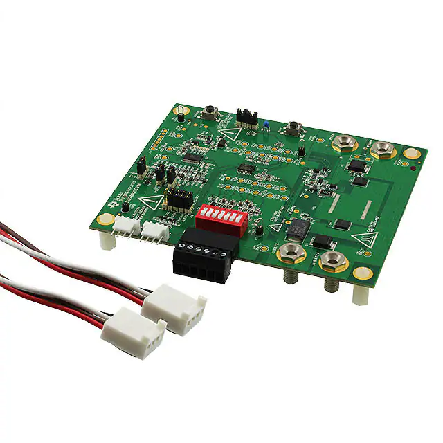


 工商网监
湘ICP备2023018690号
工商网监
湘ICP备2023018690号
