DS15BR400EVK
Quad LVDS Buffer/Repeater with Preemphasis
Evaluation Kit User Manual
August 2006
Rev 0.3
�DS15BR400 Evaluation Board User Manual
Overview
DS15BR400 is a four channel LVDS Buffer/Repeater, featuring pre-emphasis with maximum pre-emphasis gain
of approximately 6 dB at 750 MHz. The device has internal 100-ohm resistors on both, the inputs and outputs, to
improve performance and minimize board size. It utilizes LVDS technology for low power, high-speed and
superior noise immunity.
The purpose of this document is to familiarize you with the DS15BR400 Evaluation Board (DS15BR400EVK),
suggest the test setup procedures and instrumentation, and to guide you through some typical measurements
that will demonstrate the performance of the device.
Description
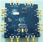
Figure 1 below represents the top layer drawing of the board with the silkscreen annotations. It is a four by four
inch six layer printed circuit board (PCB) that has a single-device layout capable of demonstrating performance
and all functions of the DS15BR400.
Figure 1: DS15BR400 Evaluation Board - Top View
2
�DS15BR400 Evaluation Board User Manual
All LVDS inputs and outputs are accessible through SMA connectors and suitable for connections to 50-ohm
instrumentation. The power can be applied using banana plugs. The control pins, PWDN* and PEM pins, are
connected to 2-position switches.
Test Setup Procedure
The following is a recommended test setup procedure for the device evaluation. Figure 2 depicts a typical setup
and instrumentation used for the device evaluation.
1. Apply the power to the device (3.3V typical) between VDD and VSS banana plug receptacles, observe
the value of ICC, and compare it with the expected value (refer to the datasheet) to ensure that the device
is functional.
2. Select I/O pairs you want to evaluate. For example, let’s say that we want to evaluate the IN0 to OUT0
signal path of the DS15BR400. The setup instructions that follow are based on this selection.
3. Connect a signal source (i.e. signal generator or an LVDS driver) to the IN0 inputs on the board and
adjust the signal parameters (VOH, VOL, VCM) so that they comply with the device input
recommendations.
4. Enable the DS15BR400 by setting PWDN* to high on CON1. Optionally, you may turn the preemphasis on for this output by setting PEM to “H” position on CON2.
5. Connect the OUT0 outputs to an oscilloscope and view the output signals with an oscilloscope with the
bandwidth of at least 3 GHz.
DS15BR400EVK
SIGNAL
GENERATOR
OR
BERT TX
IN0+
OUT0+
IN0-
OUT0-
Figure 2. Typical Test Setup
3
OSCILLOSCOPE
OR
SERIAL BERT RX
�DS15BR400 Evaluation Board User Manual
Figure 3 and 4 show an output eye diagram obtained using the DS15BR400EVK setup as in figure 2. The input
was 400mV in amplitude with 1.2 V common mode voltage 1.5 Gbps NRZ PRBS-23.
Figure 3. DS15BR400– Output Eye Diagram, Pre-emphasis OFF
Figure 4. DS15BR400 – Output Eye Diagram, Pre-emphasis On
4
�DS15BR400 Evaluation Board User Manual
Figures 5 and 6 show the eye diagrams obtained at 2 Gbps with NRZ PRBS-23.
Figure 5. DS15BR400– Output Eye Diagram, Pre-emphasis OFF
Figure 6. DS15BR400 – Output Eye Diagram, Pre-emphasis On
5
�DS15BR400 Evaluation Board User Manual
Bill Of Materials
DS15BR400 APPLICATION EVALUATION BOARD
Revised: May 21, 2006
Item
Part Type
1
CONN
2
CONN
3
CAP
4
CAP
5
CAP
Part Number
50F1460
Mfg
Description
Qty
ANY
HEADER3X1
2
CON1,CON2
NEWARK
JACK, Banana Plug Receptacle
2
CON3,CON4
ANY
0.01 F,±10%, 0603
2
C1,C4
ANY
1
C2
ANY
0.1µF, ±10%, 0603
1
C3
F, ±10%,0603
Ref Des
6
CAP
ANY
22µF, ±10%, 7343
1
C5
7
RES
ANY
100 Ohm
4
R1-R4
NEWARK
SMA, 50 Ohm, End Launch
16
SMA1-SMA16
NAT
2 GHz 4 Channel Buffer/Repeater
1
U1
8
CONN
9
IC
99F6798
PCB Stack Up
6
Notes
���������IMPORTANT NOTICE
Texas Instruments Incorporated and its subsidiaries (TI) reserve the right to make corrections, modifications, enhancements, improvements,
and other changes to its products and services at any time and to discontinue any product or service without notice. Customers should
obtain the latest relevant information before placing orders and should verify that such information is current and complete. All products are
sold subject to TI’s terms and conditions of sale supplied at the time of order acknowledgment.
TI warrants performance of its hardware products to the specifications applicable at the time of sale in accordance with TI’s standard
warranty. Testing and other quality control techniques are used to the extent TI deems necessary to support this warranty. Except where
mandated by government requirements, testing of all parameters of each product is not necessarily performed.
TI assumes no liability for applications assistance or customer product design. Customers are responsible for their products and
applications using TI components. To minimize the risks associated with customer products and applications, customers should provide
adequate design and operating safeguards.
TI does not warrant or represent that any license, either express or implied, is granted under any TI patent right, copyright, mask work right,
or other TI intellectual property right relating to any combination, machine, or process in which TI products or services are used. Information
published by TI regarding third-party products or services does not constitute a license from TI to use such products or services or a
warranty or endorsement thereof. Use of such information may require a license from a third party under the patents or other intellectual
property of the third party, or a license from TI under the patents or other intellectual property of TI.
Reproduction of TI information in TI data books or data sheets is permissible only if reproduction is without alteration and is accompanied
by all associated warranties, conditions, limitations, and notices. Reproduction of this information with alteration is an unfair and deceptive
business practice. TI is not responsible or liable for such altered documentation. Information of third parties may be subject to additional
restrictions.
Resale of TI products or services with statements different from or beyond the parameters stated by TI for that product or service voids all
express and any implied warranties for the associated TI product or service and is an unfair and deceptive business practice. TI is not
responsible or liable for any such statements.
TI products are not authorized for use in safety-critical applications (such as life support) where a failure of the TI product would reasonably
be expected to cause severe personal injury or death, unless officers of the parties have executed an agreement specifically governing
such use. Buyers represent that they have all necessary expertise in the safety and regulatory ramifications of their applications, and
acknowledge and agree that they are solely responsible for all legal, regulatory and safety-related requirements concerning their products
and any use of TI products in such safety-critical applications, notwithstanding any applications-related information or support that may be
provided by TI. Further, Buyers must fully indemnify TI and its representatives against any damages arising out of the use of TI products in
such safety-critical applications.
TI products are neither designed nor intended for use in military/aerospace applications or environments unless the TI products are
specifically designated by TI as military-grade or "enhanced plastic." Only products designated by TI as military-grade meet military
specifications. Buyers acknowledge and agree that any such use of TI products which TI has not designated as military-grade is solely at
the Buyer's risk, and that they are solely responsible for compliance with all legal and regulatory requirements in connection with such use.
TI products are neither designed nor intended for use in automotive applications or environments unless the specific TI products are
designated by TI as compliant with ISO/TS 16949 requirements. Buyers acknowledge and agree that, if they use any non-designated
products in automotive applications, TI will not be responsible for any failure to meet such requirements.
Following are URLs where you can obtain information on other Texas Instruments products and application solutions:
Products
Applications
Audio
www.ti.com/audio
Automotive and Transportation www.ti.com/automotive
Amplifiers
amplifier.ti.com
Communications and Telecom www.ti.com/communications
Data Converters
dataconverter.ti.com
Computers and Peripherals
www.ti.com/computers
DLP® Products
www.dlp.com
Consumer Electronics
www.ti.com/consumer-apps
DSP
dsp.ti.com
Energy and Lighting
www.ti.com/energy
Clocks and Timers
www.ti.com/clocks
Industrial
www.ti.com/industrial
Interface
interface.ti.com
Medical
www.ti.com/medical
Logic
logic.ti.com
Security
www.ti.com/security
Power Mgmt
power.ti.com
Space, Avionics and Defense
www.ti.com/space-avionics-defense
Microcontrollers
microcontroller.ti.com
Video and Imaging
www.ti.com/video
RFID
www.ti-rfid.com
OMAP Mobile Processors
www.ti.com/omap
Wireless Connectivity
www.ti.com/wirelessconnectivity
TI E2E Community Home Page
e2e.ti.com
Mailing Address: Texas Instruments, Post Office Box 655303, Dallas, Texas 75265
Copyright © 2012, Texas Instruments Incorporated
�


 工商网监
湘ICP备2023018690号
工商网监
湘ICP备2023018690号
