Sample &
Buy
Product
Folder
Technical
Documents
Support &
Community
Tools &
Software
LM119, LM219, LM319
SNOSBJ2B – AUGUST 2000 – REVISED JANUARY 2016
LMx19 High Speed Dual Comparator
1 Features
2 Description
•
•
•
•
•
The LM119 series are precision high-speed dual
comparators fabricated on a single monolithic chip.
They are designed to operate over a wide range of
supply voltages down to a single 5-V logic supply and
ground. They have higher gain and lower input
currents than devices such as the LM710. The
uncommitted collector of the output stage makes the
LM119 compatible with RTL, DTL, and TTL, as well
as capable of driving lamps and relays at currents of
up to 25 mA.
1
•
•
Two Independent Comparators
Operates from a Single 5-V Supply
Typically 80-ns Response Time at ±15 V
Minimum Fan-out of 2 Each Side
Maximum Input Current of 1 μA Over
Temperature
Inputs and Outputs can be Isolated from System
Ground
High Common-Mode Slew Rate
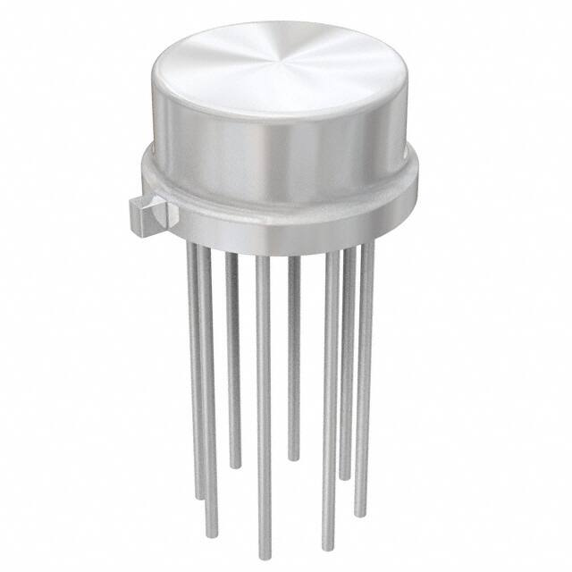
Connection Diagram
The LM319A offers improved precision over the
standard LM319, with tighter tolerances on offset
voltage, offset current, and voltage gain.
Although designed primarily for applications requiring
operation from digital logic supplies, the LM119 series
are fully specified for power supplies up to ±15 V.
The series features faster response than the LM111,
at the expense of higher power dissipation. However,
the high-speed, wide operating voltage range and low
package count make the LM119 more versatile than
older devices such as the LM711.
The LM119 is specified from −55°C to +125°C, the
LM219 is specified from −25°C to +85°C, and the
LM319A and LM319 are specified from 0°C to +70°C.
Device Information(1)
PART NUMBER
Typical Application - Relay Driver
LM119, LM219,
LM319
PACKAGE
BODY SIZE (NOM)
TO-100 (10)
8.96 mm × 8.96 mm
CDIP (14)
6.67 mm × 19.56
mm
(1) For all available packages, see the orderable addendum at
the end of the data sheet.
1
An IMPORTANT NOTICE at the end of this data sheet addresses availability, warranty, changes, use in safety-critical applications,
intellectual property matters and other important disclaimers. PRODUCTION DATA.
�LM119, LM219, LM319
SNOSBJ2B – AUGUST 2000 – REVISED JANUARY 2016
www.ti.com
Table of Contents
1
2
3
4
5
Features ..................................................................
Description .............................................................
Revision History.....................................................
Pin Configuration and Functions .........................
Specifications.........................................................
1
1
2
3
4
5.1
5.2
5.3
5.4
5.5
5.6
4
4
4
5
6
7
Absolute Maximum Ratings ......................................
ESD Ratings..............................................................
Thermal Information ..................................................
Electrical Characteristics LM119, LM219..................
Electrical Characteristics LM319, LM319A ...............
Typical Characteristics ..............................................
6
Detailed Description ............................................ 10
7
Application and Implementation ........................ 11
8
Device and Documentation Support.................. 12
6.1 Functional Block Diagram ....................................... 10
7.1 Typical Applications ................................................ 11
8.1
8.2
8.3
8.4
8.5
9
Related Links ..........................................................
Community Resources............................................
Trademarks .............................................................
Electrostatic Discharge Caution ..............................
Glossary ..................................................................
12
12
12
12
12
Mechanical, Packaging, and Orderable
Information ........................................................... 12
3 Revision History
Changes from Revision A (May 2004) to Revision B
Page
•
Changed datasheet to new TI format from National. ............................................................................................................. 1
•
Added Pin Functions and Thermal Information tables, the Device and Documentation Support section, and
Mechanical, Packaging, and Orderable Information section .................................................................................................. 1
2
Submit Documentation Feedback
Copyright © 2000–2016, Texas Instruments Incorporated
Product Folder Links: LM119 LM219 LM319
�LM119, LM219, LM319
www.ti.com
SNOSBJ2B – AUGUST 2000 – REVISED JANUARY 2016
4 Pin Configuration and Functions
D, J, or NFF Package
14-Pins CDIP and PDIP
Top View
LME Package
10-Pins TO-100 (Metal Can Package)
Top View
NAD Package
10-Pins CFP
Top View
Pin Functions
PIN
NAME
I/O
DESCRIPTION
NO.
(D, J, NFF 14)
NO.
(LME 10)
NO.
(NAD 10)
OUTPUT 1
1
12
1
O
Comparator 1 output
GND 1
2
3
2
G
Comparator 1 ground connection
INPUT 1+
3
4
3
I
Comparator 1 input
INPUT 1-
4
5
4
I
Comparator 1 input
V-
5
6
5
P
Negative supply voltage
OUTPUT 2
6
7
6
O
Comparator 2 output
GND 2
7
8
7
G
Comparator 2 ground connection
INPUT 2+
8
9
8
I
Comparator 2 input
INPUT 2-
9
10
9
I
Comparator 2 input
V+
10
11
10
P
Positive supply voltage
NC
1,2,13,14
No connect. Do not connect to ground.
Copyright © 2000–2016, Texas Instruments Incorporated
Product Folder Links: LM119 LM219 LM319
Submit Documentation Feedback
3
�LM119, LM219, LM319
SNOSBJ2B – AUGUST 2000 – REVISED JANUARY 2016
www.ti.com
5 Specifications
5.1 Absolute Maximum Ratings
over operating free-air temperature range (unless otherwise noted) (1) (2) (3)
MAX
UNIT
Total supply voltage
MIN
36
V
Output to negative supply voltage
36
V
Ground to negative supply voltage
25
V
Ground to positive supply voltage
18
V
V
Differential input voltage
–5
+5
Input voltage (4)
–15
+15
V
500
mW
Output short circuit duration
10
sec
Lead temperature (soldering, 10 sec.)
260
°C
Power dissipation (5)
Soldering information (6)
Dual-In-Line Package Soldering (10 seconds)
260
Small Outline Package Vapor Phase (60
seconds)
215
Small Outline Package Infrared (15 seconds)
Operating temperature
220
LM119
–55
125
LM219
–25
85
0
70
–65
150
LM319A, LM319
Storage temperature, Tstg
(1)
(2)
(3)
(4)
(5)
(6)
°C
°C
°C
Stresses beyond those listed under Absolute Maximum Ratings may cause permanent damage to the device. These are stress ratings
only, which do not imply functional operation of the device at these or any other conditions beyond those indicated under Recommended
Operating Conditions. Exposure to absolute-maximum-rated conditions for extended periods may affect device reliability.
If Military/Aerospace specified devices are required, please contact the Texas Instruments Sales Office/ Distributors for availability and
specifications.
Refer to RETS119X for LM119H/883 and LM119J/883 specifications.
For supply voltages less than ±15 V the absolute maximum input voltage is equal to the supply voltage.
The maximum junction temperature of the LM119 is 150°C, while that of the LM219 is 110°C. For operating at elevated temperatures,
devices in the H10 package must be derated based on a thermal resistance of 160°C/W, junction to ambient, or 19°C/W, junction to
case. The thermal resistance of the J14 and N14 packages is 100°C/W, junction to ambient.
See AN-450 “Surface Mounting Methods and Their Effect on Product Reliability” for other methods of soldering surface mount devices.
5.2 ESD Ratings
V(ESD)
(1)
Electrostatic discharge
Human body model (HBM), per ANSI/ESDA/JEDEC JS-001 (1)
VALUE
UNIT
±800
V
JEDEC document JEP155 states that 500-V HBM allows safe manufacturing with a standard ESD control process.
5.3 Thermal Information
LM119, LM219, LM319
THERMAL METRIC (1)
TO-100
(LME)
PDIP
(NFF)
CDIP
(J)
10 PINS
14 PINS
14 PINS
UNIT
RθJA
Junction-to-ambient thermal resistance
160
100
100
°C/W
RθJC(top)
Junction-to-case (top) thermal resistance
19
NA
NA
°C/W
(1)
4
For more information about traditional and new thermal metrics, see the Semiconductor and IC Package Thermal Metrics application
report, SPRA953.
Submit Documentation Feedback
Copyright © 2000–2016, Texas Instruments Incorporated
Product Folder Links: LM119 LM219 LM319
�LM119, LM219, LM319
www.ti.com
SNOSBJ2B – AUGUST 2000 – REVISED JANUARY 2016
5.4 Electrical Characteristics LM119, LM219
These specifications apply for VS = ±15 V, and the Ground pin at ground, and −55°C ≤ TA ≤ +125°C, unless otherwise stated.
With the LM219, all temperature specifications are limited to −25°C ≤ TA ≤ +85°C. The offset voltage, offset current and bias
current specifications apply for any supply voltage from a single 5-V supply up to ±15-V supplies. Do not operate the device
with more than 16 V from ground to VS.
PARAMETER
TEST CONDITIONS
(1)
MIN
TYP
MAX
UNIT
TA = 25°C, RS ≤ 5k
0.7
4
mV
Input Offset Current (1)
TA = 25°C
30
75
nA
Input Bias Current
TA = 25°C
150
500
nA
Input Offset Voltage
(2)
Voltage Gain
TA = 25°C
Response Time (3)
TA = 25°C, VS = ±15 V
Saturation Voltage
VIN ≤ −5 mV, IOUT = 25 mA
TA = 25°C
Output Leakage Current
VIN ≥ 5 mV, VOUT = 35 V
TA = 25°C
Input Offset Voltage (1)
RS ≤ 5k
Input Offset Current
10
40
V/mV
80
ns
0.75
1.5
V
0.2
2
µA
7
mV
100
nA
1000
nA
(1)
Input Bias Current
VS = ±15 V
Input Voltage Range
V+ = 5 V, V- = 0
–12
±13
1
+12
3
V
V+ ≥ 4.5 V, V− = 0
VIN ≤ −6 mV, ISINK ≤ 3.2 mA
Saturation Voltage
TA ≥ 0°C
0.23
TA ≤ 0°C
VIN ≥ 5 mV, VOUT = 35 V, V− = VGND
=0V
Output Leakage Current
0.4
V
0.6
1
Differential Input Voltage
10
±5
µA
V
Positive Supply Current
TA = 25°C, V+ = 5 V, V− = 0
Positive Supply Current
TA = 25°C, VS = ±15 V
8
11.5
mA
Negative Supply Current
TA = 25°C, VS = ±15 V
3
4.5
mA
(1)
(2)
(3)
4.3
mA
The offset voltages and offset currents given are the maximum values required to drive the output within a volt of either supply with a 1mA load. Thus, these parameters define an error band and take into account the worst case effects of voltage gain and input
impedance.
Output is pulled up to 15 V through a 1.4-kW resistor.
The response time specified is for a 100-mV input step with 5-mV overdrive.
Copyright © 2000–2016, Texas Instruments Incorporated
Product Folder Links: LM119 LM219 LM319
Submit Documentation Feedback
5
�LM119, LM219, LM319
SNOSBJ2B – AUGUST 2000 – REVISED JANUARY 2016
www.ti.com
5.5 Electrical Characteristics LM319, LM319A
These specifications apply for VS = ±15 V, and 0°C ≤ TA ≤ 70°C, unless otherwise stated. The offset voltage, offset current,
and bias current specifications apply for any supply voltage from a single 5-V supply up to ±15-V supplies. Do not operate the
device with more than 16 V from ground to VS.
PARAMETER
Input Offset Voltage (1)
Input Offset Current
(1)
TEST CONDITIONS
LM319A
MIN
TA = 25°C, RS ≤ 5k
LM319
TYP
MAX
0.5
1
MIN
UNIT
TYP
MAX
2
8
mV
nA
TA = 25°C
20
40
80
200
Input Bias Current
TA = 25°C
150
500
250
1000
Voltage Gain
TA = 25°C (2)
Response Time (3)
TA = 25°C, VS = ±15 V
Saturation Voltage
VIN ≤ −10 mV, IOUT = 25 mA
TA = 25°C
0.75
1.5
0.75
1.5
V
Output Leakage Current
VIN ≥ 10 mV, VOUT = 35 V
V− = VGND = 0 V, TA = 25°C
0.2
10
0.2
10
µA
Input Offset Voltage (1)
RS ≤ 5k
10
10
mV
300
300
nA
1200
nA
20
40
80
Input Offset Current (1)
Input Bias Current
Input Voltage Range
8
V/mV
80
ns
1000
VS = ±15 V
±13
V+ = 5 V, V- = 0
1
±13
3
nA
40
1
3
V
V+ ≥ 4.5 V, V− = 0
VIN ≤ −10 mV, ISINK ≤ 3.2 mA
0.3
Positive Supply Current
TA = 25°C, V+ = 5 V, V− = 0
4.3
Positive Supply Current
TA = 25°C, VS = ±15 V
8
12.5
8
12.5
mA
Negative Supply Current
TA = 25°C, VS = ±15 V
3
5
3
5
mA
Saturation Voltage
Differential Input Voltage
(1)
(2)
(3)
6
0.4
0.3
±5
0.4
±5
4.3
V
V
mA
The offset voltages and offset currents given are the maximum values required to drive the output within a volt of either supply with a 1mA load. Thus, these parameters define an error band and take into account the worst case effects of voltage gain and input
impedance.
Output is pulled up to 15 V through a 1.4-kW resistor.
The response time specified is for a 100-mV input step with 5-mV overdrive.
Submit Documentation Feedback
Copyright © 2000–2016, Texas Instruments Incorporated
Product Folder Links: LM119 LM219 LM319
�LM119, LM219, LM319
www.ti.com
SNOSBJ2B – AUGUST 2000 – REVISED JANUARY 2016
5.6 Typical Characteristics
5.6.1 Typical Characteristics – LM119, LM119A, LM219
Figure 1. Input Currents
Figure 2. Common-Mode Limits
Figure 3. Transfer Function
Figure 4. Response Time for Various Input Overdrives
Figure 5. Response Time for Various Input Overdrives
Figure 6. Input Characteristics
Figure 7. Response Time for Various Input Overdrives
Figure 8. Response Time for Various Input Overdrives
Copyright © 2000–2016, Texas Instruments Incorporated
Product Folder Links: LM119 LM219 LM319
Submit Documentation Feedback
7
�LM119, LM219, LM319
SNOSBJ2B – AUGUST 2000 – REVISED JANUARY 2016
www.ti.com
Typical Characteristics – LM119, LM119A, LM219 (continued)
Figure 9. Output Saturation Voltage
Figure 10. Supply Current
Figure 11. Supply Current
Figure 12. Output Limiting Characteristics
5.6.2 Typical Characteristics – LM319, LM319A
8
Figure 13. Input Currents
Figure 14. Supply Currents
Figure 15. Transfer Function
Figure 16. Response Time for Various Input Overdrives
Submit Documentation Feedback
Copyright © 2000–2016, Texas Instruments Incorporated
Product Folder Links: LM119 LM219 LM319
�LM119, LM219, LM319
www.ti.com
SNOSBJ2B – AUGUST 2000 – REVISED JANUARY 2016
Typical Characteristics – LM319, LM319A (continued)
Figure 17. Response Time for Various Input Overdrives
Figure 18. Input Characteristics
Figure 19. Response Time for Various Input Overdrives
Figure 20. Response Time for Various Input Overdrives
Figure 21. Output Saturation Voltage
Figure 22. Supply Current
Figure 23. Common-Mode Limits
Figure 24. Output Limiting Characteristics
Copyright © 2000–2016, Texas Instruments Incorporated
Product Folder Links: LM119 LM219 LM319
Submit Documentation Feedback
9
�LM119, LM219, LM319
SNOSBJ2B – AUGUST 2000 – REVISED JANUARY 2016
www.ti.com
6 Detailed Description
6.1 Functional Block Diagram
DS005705-1
∗Do not operate the LM119 with more than 16V between GND and V+
10
Submit Documentation Feedback
Copyright © 2000–2016, Texas Instruments Incorporated
Product Folder Links: LM119 LM219 LM319
�LM119, LM219, LM319
www.ti.com
SNOSBJ2B – AUGUST 2000 – REVISED JANUARY 2016
7 Application and Implementation
NOTE
Information in the following applications sections is not part of the TI component
specification, and TI does not warrant its accuracy or completeness. TI’s customers are
responsible for determining suitability of components for their purposes. Customers should
validate and test their design implementation to confirm system functionality.
7.1 Typical Applications
7.1.1 Relay Driver
Figure 25. Relay Driver
7.1.2 Window Detector
Figure 26. Window Detector
Copyright © 2000–2016, Texas Instruments Incorporated
Product Folder Links: LM119 LM219 LM319
Submit Documentation Feedback
11
�LM119, LM219, LM319
SNOSBJ2B – AUGUST 2000 – REVISED JANUARY 2016
www.ti.com
8 Device and Documentation Support
8.1 Related Links
The table below lists quick access links. Categories include technical documents, support and community
resources, tools and software, and quick access to sample or buy.
Table 1. Related Links
PARTS
PRODUCT FOLDER
SAMPLE & BUY
TECHNICAL
DOCUMENTS
TOOLS &
SOFTWARE
SUPPORT &
COMMUNITY
LM119
Click here
Click here
Click here
Click here
Click here
LM219
Click here
Click here
Click here
Click here
Click here
LM319
Click here
Click here
Click here
Click here
Click here
8.2 Community Resources
The following links connect to TI community resources. Linked contents are provided "AS IS" by the respective
contributors. They do not constitute TI specifications and do not necessarily reflect TI's views; see TI's Terms of
Use.
TI E2E™ Online Community TI's Engineer-to-Engineer (E2E) Community. Created to foster collaboration
among engineers. At e2e.ti.com, you can ask questions, share knowledge, explore ideas and help
solve problems with fellow engineers.
Design Support TI's Design Support Quickly find helpful E2E forums along with design support tools and
contact information for technical support.
8.3 Trademarks
E2E is a trademark of Texas Instruments.
All other trademarks are the property of their respective owners.
8.4 Electrostatic Discharge Caution
These devices have limited built-in ESD protection. The leads should be shorted together or the device placed in conductive foam
during storage or handling to prevent electrostatic damage to the MOS gates.
8.5 Glossary
SLYZ022 — TI Glossary.
This glossary lists and explains terms, acronyms, and definitions.
9 Mechanical, Packaging, and Orderable Information
The following pages include mechanical, packaging, and orderable information. This information is the most
current data available for the designated devices. This data is subject to change without notice and revision of
this document. For browser-based versions of this data sheet, refer to the left-hand navigation.
12
Submit Documentation Feedback
Copyright © 2000–2016, Texas Instruments Incorporated
Product Folder Links: LM119 LM219 LM319
�PACKAGE OPTION ADDENDUM
www.ti.com
13-Aug-2022
PACKAGING INFORMATION
Orderable Device
Status
(1)
Package Type Package Pins Package
Drawing
Qty
Eco Plan
(2)
Lead finish/
Ball material
MSL Peak Temp
Op Temp (°C)
Device Marking
(3)
Samples
(4/5)
(6)
LM119H
ACTIVE
TO-100
LME
10
500
Non-RoHS &
Non-Green
Call TI
Call TI
-55 to 125
( LM119H, LM119H)
Samples
LM119H/NOPB
ACTIVE
TO-100
LME
10
500
RoHS & Green
Call TI
Level-1-NA-UNLIM
-55 to 125
( LM119H, LM119H)
Samples
LM119J
ACTIVE
CDIP
J
14
25
Non-RoHS
& Green
Call TI
Level-1-NA-UNLIM
-55 to 125
LM119J
Samples
LM319AM
ACTIVE
SOIC
D
14
55
Non-RoHS
& Green
Call TI
Level-1-235C-UNLIM
0 to 70
LM319AM
Samples
LM319AM/NOPB
ACTIVE
SOIC
D
14
55
RoHS & Green
SN
Level-1-260C-UNLIM
0 to 70
LM319AM
Samples
LM319AMX/NOPB
ACTIVE
SOIC
D
14
2500
RoHS & Green
SN
Level-1-260C-UNLIM
0 to 70
LM319AM
Samples
LM319M
ACTIVE
SOIC
D
14
55
Non-RoHS
& Green
Call TI
Level-1-235C-UNLIM
0 to 70
LM319M
Samples
LM319M/NOPB
ACTIVE
SOIC
D
14
55
RoHS & Green
SN
Level-1-260C-UNLIM
0 to 70
LM319M
Samples
LM319MX/NOPB
ACTIVE
SOIC
D
14
2500
RoHS & Green
SN
Level-1-260C-UNLIM
0 to 70
LM319M
Samples
LM319N/NOPB
ACTIVE
PDIP
N
14
25
RoHS & Green
NIPDAU
Level-1-NA-UNLIM
0 to 70
LM319N
Samples
(1)
The marketing status values are defined as follows:
ACTIVE: Product device recommended for new designs.
LIFEBUY: TI has announced that the device will be discontinued, and a lifetime-buy period is in effect.
NRND: Not recommended for new designs. Device is in production to support existing customers, but TI does not recommend using this part in a new design.
PREVIEW: Device has been announced but is not in production. Samples may or may not be available.
OBSOLETE: TI has discontinued the production of the device.
(2)
RoHS: TI defines "RoHS" to mean semiconductor products that are compliant with the current EU RoHS requirements for all 10 RoHS substances, including the requirement that RoHS substance
do not exceed 0.1% by weight in homogeneous materials. Where designed to be soldered at high temperatures, "RoHS" products are suitable for use in specified lead-free processes. TI may
reference these types of products as "Pb-Free".
RoHS Exempt: TI defines "RoHS Exempt" to mean products that contain lead but are compliant with EU RoHS pursuant to a specific EU RoHS exemption.
Green: TI defines "Green" to mean the content of Chlorine (Cl) and Bromine (Br) based flame retardants meet JS709B low halogen requirements of


 工商网监
湘ICP备2023018690号
工商网监
湘ICP备2023018690号
