User's Guide
SNOA535B – October 2008 – Revised May 2013
AN-1906 LMH6518 Evaluation Board
1
Package Includes
•
•
•
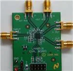
LMH6518 evaluation board (tested board that takes a 5 V and ground power supply connection and
outputs main and auxiliary differential outputs).
USB Interface board (Figure 1) with 10 pin interconnect cable (to mate with J6 on LMH6518 evaluation
board). This board interfaces to a PC USB port to “Write” the SPI interface signals to the LMH6518
and can also display the LMH6518 state through “Read” back.
USB Cable
Figure 1. USB Interface Board
All trademarks are the property of their respective owners.
SNOA535B – October 2008 – Revised May 2013
Submit Documentation Feedback
Copyright © 2008–2013, Texas Instruments Incorporated
AN-1906 LMH6518 Evaluation Board
1
�Additional Items Needed
2
www.ti.com
Additional Items Needed
•
•
PC (Windows) with web connection
A single ended input signal for testing the LMH6518. The input signal should be of the speed, purity,
and fidelity needed to test LMH6518 functionality and to not limit measured performance. The
LMH6518 has differential input; however, this evaluation board is configured for single ended drive
(into the positive input, “+IN” (J3) SMA connector) and the undriven input is biased to VCC/2 (= 2.5 V)
on board. This input should be offset to 2.5 V DC (< ±1 mV of the undriven input voltage at R19 or
LMH6518 pin 7). Here are possible input sources:
– Lab generator (or other signal source) capable of 2.5 V offset in the presence of milli-volt level input
signal.
– Using a ground referenced (AC coupled or no offset adjust needed) generator with a “Bias-Tee”
module that allows DC value to be set to 2.5 V using a fine tuned voltage lab DC power supply.
NOTE: If necessary, decouple the lab power supply with an effective low-pass filter (series R,
shunt C) next to the “Bias-Tee” DC input to ensure little interference coupling to the
signal path.
– A Hi-Z buffer that outputs the required mill-volt level AC signal centered at 2.5 V from a ground
referenced input signal. In oscilloscope applications, this Hi-Z buffer is what interfaces the highimpedance oscilloscope probe to the LMH6518. The LMH6518 900 MHz, Digitally Controlled,
Variable Gain Amplifier Data Sheet (SNOSB21) details a circuit that performs this function.
3
Setup and Operation
3.1
Preliminary Setup
1. Install Microsoft .NET Framework version 2.0 prior to installing the LMH6518 evaluation software (that
is available for download from www.ti.com - evaluation board page). Point your browser to the
following location:
(a) http://www.microsoft.com and search for “.NET Framework”.
(b) Continue to the page link where “Download” is located. The .NET Framework installation file,
“dotnetfx.exe”, can be downloaded by clicking on the “Download” button.
2. Download “dotnetfx.exe” and save to any folder on the PC. Continue to Run and install this program.
3. Follow the LMH6518 Product Folder (SNOA535), “Eval. Boards”, “Buy Now” and click on the “Software
Setup Files”.
4. Go to that folder and run setup.exe. Continue with the installation.
5. When the LMH6518 software installation completes, there would be a shortcut to the LMH6518
evaluation software on the PC desktop. Double click to run the software.
6. Apply 5 V (±20 mV) DC and ground to the LMH6518 evaluation board. The power supply should be
capable of at least 300 mA of current. Ensure the power connection to the evaluation board is properly
made or damage may occur.
2
AN-1906 LMH6518 Evaluation Board
SNOA535B – October 2008 – Revised May 2013
Submit Documentation Feedback
Copyright © 2008–2013, Texas Instruments Incorporated
�Setup and Operation
www.ti.com
7. Plug the 10 pin female end of the ribbon cable from the USB Interface board into J6 on the LMH6518
evaluation board. The ribbon cable pin 1 should connect to J6 pin 1 (J6 pin 1 has square pad on the
board bottom, and a “1” silk-screened on the top side of the board, for easy identification). Table 1
shows the connections to the USB interface board (for reference only).
Table 1. USB Interface Board/ LMH6518 Evaluation Board Interconnect Detail
Name
Function
LMH6518 Evaluation Board Pin (J6)
USB Interface Board (X4)
Ground
Ground
1
“GND”, pin 2
CS
Chip Select
3
A7, pin 1
Data out (LMH6518 SDIO pin)
4
A0, pin 15
Clock
5
A6, pin 3
Data In (LMH6518 SDIO pin)
7
L7, pin 6
DO
(1)
SCLK
DI
(1)
(1)
DI and DO are tied together on the LMH6518 evaluation board, and connected to LMH6518 SDIO pin for bidirectional data read
or write.
8. Plug the USB Interface board to a free USB port, with the other end mating with the USB port on the
USB Interface board, and launch the LMH6518 software, if not already. If a pop-up window appears,
click “yes to upload the correct setup to the USB Interface board and you are now ready to control the
LMH6518. When the application is running, you should see “USB Connected All ACK” in the Status
Bar at the bottom-left of the LMH6518 software window shown in Figure 3. If the status bar message
does not appear, un-plug the USB cable and reapply to reinitiate the USB Interface board and until the
proper message appears.
3.2
LMH6518 Evaluation Board Setup
Refer to the board schematic and layout documents.
1. Jumper Placement: The LMH6518 evaluation board generates the 3.3 V logic supply on board
(Jumper JP3, pins 1-2 shorted powers the LMH6518 off the on-board 3.3 V source.
NOTE: JP3, pin 1 has a ”1” silk-screened next to it on the top side of the board). The output
common mode voltage (Main and Auxiliary outputs both) are set to about 1.2V using an
onboard voltage divider (R1, and R2) from VCC (+5 V). R21 and R22 (0 Ω resistors) tie this 1.2 V
level to both main and auxiliary common mode inputs (“VCM” and “VCM_AUX” that are pins 13
and 16, respectively).
2. Outputs: The main outputs of the LMH6518 appear at J1 and J2 (SMA connectors). These connectors
can be tied directly to a Texas Instruments Gsample/second ADC (ADC081500), or equivalent, for DC
coupled data acquisition. Done this way, pin 9 of J6 (VCMO) can be tied to the common mode output
control of the ADC to allow the ADC to control the LMH6518 output common mode voltage. Note that
R3 = 10K and C1 = 1 nF would need to be installed on the evaluation board for this kind of testing. In
addition, move R21 and R22 (0Ω resistors) to R23 and R24 in order to disconnect the onboard 1.2 V
reference and instead allow the ADC to control the main and auxiliary common mode voltages.
The auxiliary outputs, that can be terminated in 100 Ω on board by installing R4 (100 Ω), appear at J8
and J7. Note that the auxiliary outputs (used for trigger function in oscilloscope applications) are very
similar to the main outputs, with the exception of slightly higher distortion levels. The auxiliary outputs
are available at J8 and J7 SMA connectors.
J1, and J2 (and also J7, and J8) differential impedance should be close to 100 Ω with minimal parasitic
effects when being measured. As these outputs are all at approximately 1.2 V common mode level,
they cannot be terminated in DC coupled 50 Ω (similar to an oscilloscope input) directly. AC coupled
50 Ω terminated instrumentation (such as S parameter analyzers) can be connected to these SMA
outputs directly for observation. With single ended Hi-Z input instrument observation, the LMH6518
outputs should be terminated in 100 Ω differential, as shown in Figure 2 (beware of the loading effect
of such an observation on the LMH6518 outputs).
SNOA535B – October 2008 – Revised May 2013
Submit Documentation Feedback
Copyright © 2008–2013, Texas Instruments Incorporated
AN-1906 LMH6518 Evaluation Board
3
�Miscellaneous
www.ti.com
+OUT
DC Coupled Hi-Z
Input Instrument
LMH6518
100:
DC Coupled Hi-Z
Input Instrument
-OUT
Figure 2. LMH6518 Output Observation With Hi-Z Instrumentation
3. Input(s): Ensure that the LMH6518 inputs (LMH6518 pins 6 and 7) are both close to VCC/2 (= 2.5 V)
and there is less than 1 mV of difference in voltage between them. On the board, use a DC voltmeter
to measure LMH6518 pin 6 and 7 voltages (or C14 and R19, right hand side pads). LMH6518 pin 6
potential (driven input) can be controlled by varying the incoming signal offset (2.5 V nominal) at J3
(SMA connector). If the two LMH6518 inputs are not offset close to each other, as stated, measured
results could be affected. Some of the side-effects of input offset are: output clipping, excess distortion,
loss of bandwidth, or step response anomalies.
Potentiometer R25 (board bottom side) is provided to null any remnant output offset, especially useful
when the LMH6518 operating conditions change. For an effective method of input offset adjustment,
especially when the LMH6518 is set for high gain (HG/ 0 dB), monitor J1 and J2 (outputs) SMA center
pins (1.2 V nominal) with a DVM set to read DC voltage and adjust R25 to minimize the voltage
difference between these two outputs to less than 50 mV. This will reduce any input offset so that the
output can be observed.
4
Miscellaneous
1. Overlapping gain state: As shown in Table 2, one of the possible gain states (18.8 dB) is covered by
either preamp HG, or preamp LG. This gain is possible with preamp set to high gain and 20 dB ladder
attenuation, or, with preamp set to low gain and 0 dB ladder attenuation. Choose preamp high gain
(with 20 dB ladder attenuation) for best noise performance or preamp low gain (with 0 dB ladder
attenuation) for best distortion performance
Table 2. LMH6518 Gain Map
Attenuation (dB)
Preamp Gain
0
2
4
6
8
10
12
14
16
18
20
Lo
18.8
16.8
14.8
12.8
10.8
8.8
6.8
4.8
2.8
0.8
−1.16
Hi
38.8
36.8
34.8
32.8
30.8
28.8
26.8
24.8
22.8
20.8
18.8
2. LMH6518 Evaluation Software Look:
Ladder Attenuator: 0 dB to 20 dB. 10 steps. Each step is 2 dB
Total Gain: This displays the total device gain (read only, assuming 100 Ω differential load across J2
and J1 SMA or J8 and J7 outputs) based on the preamp gain and the ladder attenuation selected
Filters: Full (no filter), 20 MHz, 100 MHz, 200 MHz, 350 MHz, 650 MHz, and 750 MHz.
Power Mode: Full power and Aux Hi-Z (with Aux Hi-Z, the auxiliary output is turned off with
approximately 60 mA reduction in 5 V supply current)
Preamp Gain: Hi gain and low gain (with 20 dB difference between the two)
Write: To write the current setup on the GUI screen into the LMH6518 registers. To change any of the
LMH6518 operating registers, the adjustments should be made first, followed by a single click on the
“Write” button.
Read: To read back all LMH6518 registers for confirmation and verification. If the register Read back is
different from the last Write state, the software displays an alert window.
Exit: To close the application
4
AN-1906 LMH6518 Evaluation Board
SNOA535B – October 2008 – Revised May 2013
Submit Documentation Feedback
Copyright © 2008–2013, Texas Instruments Incorporated
�Miscellaneous
www.ti.com
Figure 3. Evaluation Software Screen Shot
3. Default device turn-on state: Preamp low gain, 20 dB ladder attenuation, full-power mode, filter full.
With the USB interface board connected, the LMH6518 evaluation board will remain powered on
through the interconnect to the USB interface board, even if the 5 V supply to the board is
disconnected. Therefore, the device states will not reset to default power-on even if the power is turned
off.
4. When the power mode is switched, the change in +5 V supply current (∼60 mA) through the power
supply wiring/trace is enough to cause a noticeable difference in the voltage at “−IN“ (voltage-divided
from 5 V supply). This could cause enough input offset difference to shift or rail the output, especially
at high gains (preamp HG and little or no ladder attenuation). If this occurs, readjust R25 (bottom side of
the board) as described in Section 3.2 to null the output offset that is caused by the way the undriven
input is biased. This is merely a consequence of how the undriven input is biased.
In an oscilloscope application, the driven input’s offset needs to be servo’d to the undriven input
potential, similar to the JFET LNA shown in LMH6518 900 MHz, Digitally Controlled, Variable Gain
Amplifier Data Sheet (SNOSB21); thus, the cause is eliminated.
SNOA535B – October 2008 – Revised May 2013
Submit Documentation Feedback
Copyright © 2008–2013, Texas Instruments Incorporated
AN-1906 LMH6518 Evaluation Board
5
�IMPORTANT NOTICE
Texas Instruments Incorporated and its subsidiaries (TI) reserve the right to make corrections, enhancements, improvements and other
changes to its semiconductor products and services per JESD46, latest issue, and to discontinue any product or service per JESD48, latest
issue. Buyers should obtain the latest relevant information before placing orders and should verify that such information is current and
complete. All semiconductor products (also referred to herein as “components”) are sold subject to TI’s terms and conditions of sale
supplied at the time of order acknowledgment.
TI warrants performance of its components to the specifications applicable at the time of sale, in accordance with the warranty in TI’s terms
and conditions of sale of semiconductor products. Testing and other quality control techniques are used to the extent TI deems necessary
to support this warranty. Except where mandated by applicable law, testing of all parameters of each component is not necessarily
performed.
TI assumes no liability for applications assistance or the design of Buyers’ products. Buyers are responsible for their products and
applications using TI components. To minimize the risks associated with Buyers’ products and applications, Buyers should provide
adequate design and operating safeguards.
TI does not warrant or represent that any license, either express or implied, is granted under any patent right, copyright, mask work right, or
other intellectual property right relating to any combination, machine, or process in which TI components or services are used. Information
published by TI regarding third-party products or services does not constitute a license to use such products or services or a warranty or
endorsement thereof. Use of such information may require a license from a third party under the patents or other intellectual property of the
third party, or a license from TI under the patents or other intellectual property of TI.
Reproduction of significant portions of TI information in TI data books or data sheets is permissible only if reproduction is without alteration
and is accompanied by all associated warranties, conditions, limitations, and notices. TI is not responsible or liable for such altered
documentation. Information of third parties may be subject to additional restrictions.
Resale of TI components or services with statements different from or beyond the parameters stated by TI for that component or service
voids all express and any implied warranties for the associated TI component or service and is an unfair and deceptive business practice.
TI is not responsible or liable for any such statements.
Buyer acknowledges and agrees that it is solely responsible for compliance with all legal, regulatory and safety-related requirements
concerning its products, and any use of TI components in its applications, notwithstanding any applications-related information or support
that may be provided by TI. Buyer represents and agrees that it has all the necessary expertise to create and implement safeguards which
anticipate dangerous consequences of failures, monitor failures and their consequences, lessen the likelihood of failures that might cause
harm and take appropriate remedial actions. Buyer will fully indemnify TI and its representatives against any damages arising out of the use
of any TI components in safety-critical applications.
In some cases, TI components may be promoted specifically to facilitate safety-related applications. With such components, TI’s goal is to
help enable customers to design and create their own end-product solutions that meet applicable functional safety standards and
requirements. Nonetheless, such components are subject to these terms.
No TI components are authorized for use in FDA Class III (or similar life-critical medical equipment) unless authorized officers of the parties
have executed a special agreement specifically governing such use.
Only those TI components which TI has specifically designated as military grade or “enhanced plastic” are designed and intended for use in
military/aerospace applications or environments. Buyer acknowledges and agrees that any military or aerospace use of TI components
which have not been so designated is solely at the Buyer's risk, and that Buyer is solely responsible for compliance with all legal and
regulatory requirements in connection with such use.
TI has specifically designated certain components as meeting ISO/TS16949 requirements, mainly for automotive use. In any case of use of
non-designated products, TI will not be responsible for any failure to meet ISO/TS16949.
Products
Applications
Audio
www.ti.com/audio
Automotive and Transportation
www.ti.com/automotive
Amplifiers
amplifier.ti.com
Communications and Telecom
www.ti.com/communications
Data Converters
dataconverter.ti.com
Computers and Peripherals
www.ti.com/computers
DLP® Products
www.dlp.com
Consumer Electronics
www.ti.com/consumer-apps
DSP
dsp.ti.com
Energy and Lighting
www.ti.com/energy
Clocks and Timers
www.ti.com/clocks
Industrial
www.ti.com/industrial
Interface
interface.ti.com
Medical
www.ti.com/medical
Logic
logic.ti.com
Security
www.ti.com/security
Power Mgmt
power.ti.com
Space, Avionics and Defense
www.ti.com/space-avionics-defense
Microcontrollers
microcontroller.ti.com
Video and Imaging
www.ti.com/video
RFID
www.ti-rfid.com
OMAP Applications Processors
www.ti.com/omap
TI E2E Community
e2e.ti.com
Wireless Connectivity
www.ti.com/wirelessconnectivity
Mailing Address: Texas Instruments, Post Office Box 655303, Dallas, Texas 75265
Copyright © 2013, Texas Instruments Incorporated
�


 工商网监
湘ICP备2023018690号
工商网监
湘ICP备2023018690号
