Sample &
Buy
Product
Folder
Support &
Community
Tools &
Software
Technical
Documents
Reference
Design
LP38690, LP38692
SNVS322M – DECEMBER 2004 – REVISED DECEMBER 2015
LP38690, LP38692 1-A Low Dropout CMOS Linear Regulators
Stable with Ceramic Output Capacitors
1 Features
3 Description
•
•
•
The LP38690 and LP38692 low-dropout CMOS linear
regulators provide tight output tolerance (2.5%
typical), extremely low dropout voltage (450 mV at a
1-A load current, VOUT = 5 V), and excellent AC
performance utilizing ultra low ESR ceramic output
capacitors.
1
•
•
•
•
•
•
•
•
•
Wide Input Voltage Range (2.7 V to 10 V)
2.5% Output Accuracy (25°C)
Low Dropout Voltage: 450 mV at 1 A
(typical, 5 VOUT)
Precision (Trimmed) Bandgap Reference
Ensured Specifications for –40°C to 125°C
1-µA Off-State Quiescent Current
Thermal Overload Protection
Foldback Current Limiting
3-Lead TO-252, 5-Lead SOT-223, and 6-Bump
WSON Packages
Enable Pin (LP38692)
Ground Pin Current: 55 µA (typical) at Full Load
Precision Output Voltage: 2.5% (25°C) Accuracy
The use of a PMOS power transistor means that no
DC base drive current is required to bias it allowing
ground pin current to remain below 100 µA
regardless of load current, input voltage, or operating
temperature.
Device Information(1)
PART NUMBER
2 Applications
•
•
•
•
The low thermal resistance of the WSON, SOT-223,
and TO-252 packages allow the full operating current
to be used even in high ambient temperature
environments.
LP38690
Hard Disk Drives
Notebook Computers
Battery Powered Devices
Portable Instrumentation
LP38692
VIN
VOUT
WSON (6)
3.00 mm x 3.00 mm
SOT-223 (5)
6.50 mm x 3.56 mm
WSON (6)
3.00 mm x 3.00 mm
Simplified Schematic for LP38692
VOUT
VIN
IN
OUT
LP38690
EN
SNS**
1 µF*
BODY SIZE (NOM)
6.58 mm x 6.10 mm
(1) For all available packages, see the orderable addendum at
the end of the data sheet.
Simplified Schematic for LP38690
IN
PACKAGE
TO-252 (3)
GND
* Minimum value required for stability.
**WSON package devices only.
OUT
LP38692
SNS**
VEN
1 µF*
1 PF *
GND
1 PF *
* Minimum value required for stability.
**WSON package devices only.
1
An IMPORTANT NOTICE at the end of this data sheet addresses availability, warranty, changes, use in safety-critical applications,
intellectual property matters and other important disclaimers. PRODUCTION DATA.
�LP38690, LP38692
SNVS322M – DECEMBER 2004 – REVISED DECEMBER 2015
www.ti.com
Table of Contents
1
2
3
4
5
6
7
1
1
1
2
3
4
9 Power Supply Recommendations...................... 18
10 Layout................................................................... 18
6.1
6.2
6.3
6.4
6.5
6.6
4
4
4
4
5
6
11 Device and Documentation Support ................. 21
Absolute Maximum Ratings ......................................
ESD Ratings..............................................................
Recommended Operating Conditions.......................
Thermal Information ..................................................
Electrical Characteristics...........................................
Typical Characteristics ..............................................
Detailed Description ............................................ 11
7.1
7.2
7.3
7.4
8
8.1 Application Information............................................ 14
8.2 Typical Applications ................................................ 15
Features ..................................................................
Applications ...........................................................
Description .............................................................
Revision History.....................................................
Pin Configuration and Functions .........................
Specifications.........................................................
Overview .................................................................
Functional Block Diagrams .....................................
Feature Description.................................................
Device Functional Modes........................................
11
11
13
13
Application and Implementation ........................ 14
10.1
10.2
10.3
10.4
10.5
11.1
11.2
11.3
11.4
11.5
11.6
PCB Layout ...........................................................
Layout Examples...................................................
WSON Mounting ...................................................
RFI/EMI Susceptibility ...........................................
Output Noise .........................................................
Documentation Support .......................................
Related Links ........................................................
Community Resources..........................................
Trademarks ...........................................................
Electrostatic Discharge Caution ............................
Glossary ................................................................
18
19
19
20
20
21
21
21
21
21
21
12 Mechanical, Packaging, and Orderable
Information ........................................................... 21
4 Revision History
NOTE: Page numbers for previous revisions may differ from page numbers in the current version.
Changes from Revision L (March 2015) to Revision M
Page
•
Added top navigator icon for TI Designs ............................................................................................................................... 1
•
Added Caution note to Foldback Current Limiting subsection ............................................................................................ 13
Changes from Revision K (December 2014) to Revision L
•
Changed "mA" back to "mV" - error from SDS conversion. ................................................................................................... 5
Changes from Revision J (April 2013) to Revision K
•
2
Page
Changed Device Information and ESD Rating tables, Feature Description, Device Functional Modes, Application
and Implementation, Power Supply Recommendations, Layout, Device and Documentation Support, and
Mechanical, Packaging, and Orderable Information sections; update Thermal Values moved some curves to
Application Curves section; change package name PFM to TO-252 (National to TI nomenclature) and pin names
from VIN, VOUT to IN, OUT. ................................................................................................................................................. 1
Changes from Revision I (April 2013) to Revision J
•
Page
Page
Changed layout of National Data Sheet to TI format ........................................................................................................... 20
Submit Documentation Feedback
Copyright © 2004–2015, Texas Instruments Incorporated
Product Folder Links: LP38690 LP38692
�LP38690, LP38692
www.ti.com
SNVS322M – DECEMBER 2004 – REVISED DECEMBER 2015
5 Pin Configuration and Functions
LP38690 TO-252 (NDP)
3 Pins
Top View
LP38690 WSON (NGG)
6 Pins
Top View
IN
1
GND
2
N/C
3
LP38690/92 SOT-223 (NDC)
5 Pins
Top View
Exposed Pad
on Bottom
(DAP)
6
IN
5
SNS
4
OUT
LP38692 WSON (NGG)
6 Pins
Top View
EN 1
IN
1
GND
2
EN
3
6
IN
5
SNS
4
OUT
N/C 2
5 GND
OUT 3
IN 4
Exposed Pad
on Bottom
(DAP)
Pin Functions
PIN
NAME
LP38690
LP38692
TYPE
DESCRIPTION
TO-252
WSON
SOT-223
WSON
EN
—
—
1
3
I
The Enable (EN) pin allows the part to be turned ON and OFF by pulling this
pin HIGH or LOW.
GND
TAB
2
5
2
—
Circuit ground for the regulator. For the TO-252 and SOT-223 packages this
is thermally connected to the die and functions as a heat sink when soldered
down to a large copper plane.
IN
3
1, 6
4
1, 6
I
This is the input supply voltage to the regulator. For WSON devices, both IN
pins must be tied together for full current operation (500 mA maximum per
pin).
OUT
1
4
3
4
O
Regulated output voltage.
SNS
—
5
—
5
I
WSON only - Output sense pin allows remote sensing at the load which
eliminates the error in output voltage due to voltage drops caused by the
resistance in the traces between the regulator and the load. This pin must
be tied to VOUT.
DAP
—
X
—
X
—
WSON only - The DAP (Exposed Pad) functions as a thermal connection
when soldered to a copper plane. See WSON Mounting section in Layout for
more information.
Submit Documentation Feedback
Copyright © 2004–2015, Texas Instruments Incorporated
Product Folder Links: LP38690 LP38692
3
�LP38690, LP38692
SNVS322M – DECEMBER 2004 – REVISED DECEMBER 2015
www.ti.com
6 Specifications
6.1 Absolute Maximum Ratings
over operating free-air temperature range (unless otherwise noted) (1)
V(max) All pins (with respect to GND)
IOUT
MIN
MAX
UNIT
–0.3
12
V
(2)
Internally limited
−40
Junction temperature
150
Lead temperature (soldering, 5 seconds)
Power dissipation (3)
Internally limited
Storage temperature, Tstg
(1)
(2)
(3)
°C
260
–65
150
°C
Stresses beyond those listed under Absolute Maximum Ratings may cause permanent damage to the device. These are stress ratings
only, which do not imply functional operation of the device at these or any other conditions beyond those indicated under Recommended
Operating Conditions. Exposure to absolute-maximum-rated conditions for extended periods may affect device reliability.
If used in a dual-supply system where the regulator load is returned to a negative supply, the output pin must be diode clamped to
ground.
At elevated temperatures, device power dissipation must be derated based on package thermal resistance and heatsink values (if a
heatsink is used). When using the WSON package, refer to TI Application Report AN-1187 Leadless Leadframe Package (LLP)
(SNOA401) and the WSON Mounting section in this datasheet. If power dissipation causes the junction temperature to exceed specified
limits, the device goes into thermal shutdown.
6.2 ESD Ratings
V(ESD)
(1)
Electrostatic discharge
Human-body model (HBM), per ANSI/ESDA/JEDEC JS-001 (1)
VALUE
UNIT
±2000
V
JEDEC document JEP155 states that 500-V HBM allows safe manufacturing with a standard ESD control process.
6.3 Recommended Operating Conditions
over operating free-air temperature range (unless otherwise noted)
MIN
VIN supply voltage
Operating junction temperature
NOM
MAX
UNIT
2.7
10
V
−40
125
°C
6.4 Thermal Information
THERMAL METRIC (1)
LP38690
LP38690/92
LP38692
TO-252
WSON
SOT-223
3 PINS
6 PINS
5 PINS
UNIT
RθJA (2)
Junction-to-ambient thermal resistance
50.5
50.6
68.5
°C/W
RθJC(top)
Junction-to-case (top) thermal resistance
52.6
44.4
52.2
°C/W
RθJB
Junction-to-board thermal resistance
29.7
24.9
13.0
°C/W
ψJT
Junction-to-top characterization parameter
4.8
0.4
5.5
°C/W
ψJB
Junction-to-board characterization parameter
29.3
25.1
12.8
°C/W
RθJC(bot)
Junction-to-case (bottom) thermal resistance
1.5
5.4
n/a
°C/W
(1)
(2)
4
For more information about traditional and new thermal metrics, see the Semiconductor and IC Package Thermal Metrics application
report, SPRA953.
Junction-to-ambient thermal resistance, High-K.
Submit Documentation Feedback
Copyright © 2004–2015, Texas Instruments Incorporated
Product Folder Links: LP38690 LP38692
�LP38690, LP38692
www.ti.com
SNVS322M – DECEMBER 2004 – REVISED DECEMBER 2015
6.5 Electrical Characteristics
Unless otherwise specified: VIN = VOUT + 1 V, CIN = COUT = 10 µF, ILOAD = 10 mA, and limits are for TJ = 25°C. Minimum (MIN)
and maximum (MAX) limits are specified through testing, statistical correlation, or design.
PARAMETER
VOUT
ΔVOUT/ΔVIN
ΔVOUT/ΔIL
Output voltage tolerance
Output voltage line
regulation (2)
Output voltage load
regulation (3)
TEST CONDITIONS
100 µA < IL < 1 A
VO + 1 V ≤ VIN ≤ 10 V
−40°C ≤ TJ ≤ 125°C
VOUT + 0.5 V ≤ VIN ≤ 10 V
IL = 25 mA
MIN
TYP (1)
2.5
–5
5
%/A
1.8
V
1 mA < IL < 1 A
VIN = VOUT + 1 V
−40°C ≤ TJ ≤ 125°C
5
VOUT = 1.8 V
IL = 1 A
950
VOUT = 1.8 V
IL = 1 A
−40°C ≤ TJ ≤ 125°C
VIN – VOUT
Dropout voltage (4)
VOUT = 3.3 V
VOUT = 3.3 V
−40°C ≤ TJ ≤ 125°C
VOUT = 5 V
VOUT = 5 V,
−40°C ≤ TJ ≤ 125°C
1600
IL = 0.1 A
IL = 1 A
Quiescent current
80
800
IL = 0.1 A
145
IL = 1 A
IL = 0.1 A
IL = 1 A
1300
650
110
IL = 1 A
IL = 0.1 A
IL = 1 A
1000
45
450
IL = 0.1 A
100
IL = 1 A
800
55
VIN ≤ 10 V, IL = 100 µA to 1 A
−40°C ≤ TJ ≤ 125°C
VEN ≤ 0.4 V (LP38692 only)
100
VIN – VOUT ≤ 4 V
−40°C ≤ TJ ≤ 125°C
Minimum load current
IFB
Foldback current limit
PSRR
Ripple rejection
TSD
Thermal shutdown
activation (junction temp)
160
TSD (HYST)
Thermal shutdown
hysteresis (junction temp)
10
en
Output noise
VOUT = 3.3 V, BW = 10 Hz to 10 kHz
0.7
VOUT (LEAK)
Output leakage current
VOUT = VOUT(NOM) + 1 V at 10 VIN
0.5
(1)
(2)
(3)
(4)
µA
0.001
IL(MIN)
100
VIN – VOUT > 5 V
450
VIN – VOUT < 4 V
1500
VIN = VOUT + 2 V(DC), with 1V(p-p) / 120
Hz ripple
mV
65
IL = 0.1 A
VIN ≤ 10 V, IL = 100 µA to 1 A
IQ
%VOUT
1
1 mA < IL < 1 A
VIN = VOUT + 1 V
VOUT = 2.5 V
−40°C ≤ TJ ≤ 125°C
UNIT
0.03
VOUT + 0.5 V ≤ VIN ≤ 10 V
IL = 25 mA
−40°C ≤ TJ ≤ 125°C
VOUT = 2.5 V
MAX
–2.5
mA
55
dB
°C
µV/√Hz
12
µA
Typical numbers represent the most likely parametric norm for 25°C operation.
Output voltage line regulation is defined as the change in output voltage from nominal value resulting from a change in input voltage.
Output voltage load regulation is defined as the change in output voltage from nominal value as the load current increases from 1 mA to
full load.
Dropout voltage is defined as the minimum input to output differential required to maintain the output within 100 mV of nominal value.
Submit Documentation Feedback
Copyright © 2004–2015, Texas Instruments Incorporated
Product Folder Links: LP38690 LP38692
5
�LP38690, LP38692
SNVS322M – DECEMBER 2004 – REVISED DECEMBER 2015
www.ti.com
Electrical Characteristics (continued)
Unless otherwise specified: VIN = VOUT + 1 V, CIN = COUT = 10 µF, ILOAD = 10 mA, and limits are for TJ = 25°C. Minimum (MIN)
and maximum (MAX) limits are specified through testing, statistical correlation, or design.
PARAMETER
TEST CONDITIONS
TYP (1)
MIN
MAX
Output = OFF, −40°C ≤ TJ ≤ 125°C
Enable voltage (LP38692
only)
VEN
IEN
Enable pin leakage
UNIT
0.4
Output = ON, VIN = 4 V
−40°C ≤ TJ ≤ 125°C
1.8
Output = ON, VIN = 6 V
−40°C ≤ TJ ≤ 125°C
3
Output = ON, VIN = 10 V
−40°C ≤ TJ ≤ 125°C
4
VEN = 0 V or 10 V, VIN = 10 V
V
–1
0.001
1
µA
6.6 Typical Characteristics
Unless otherwise specified: TJ = 25°C, CIN = COUT = 10 µF, EN pin is tied to VIN (LP38692 only), VOUT = 1.8 V, VIN = VOUT + 1
V, IL = 10 mA.
1.0
1.2
COUT = 10 PF
COUT = 1 PF
Hz)
0.8
0.8
NOISE (PV/
NOISE/ (PV
Hz)
1.0
0.6
0.4
0.6
0.4
0.2
0.2
0.0
0.0
10
100
1k
10k
100k
10
100
FREQUENCY (Hz)
1.5
100k
60
COUT = 100 PF
50
RIPPLE REJECTION (dB)
Hz)
10k
Figure 2. Noise vs Frequency
Figure 1. Noise vs Frequency
NOISE (PV/
1k
FREQUENCY (Hz)
1.0
0.5
40
30
COUT = 10 PF
20
VIN(DC) = 5.3V
VIN(AC) = 1V(p-p)
10
VOUT = 3.3V
0.0
0
10
100
1k
10k
100k
10
1k
10k
100k
FREQUENCY (Hz)
FREQUENCY (Hz)
Figure 3. Noise vs Frequency
6
100
Submit Documentation Feedback
Figure 4. Ripple Rejection
Copyright © 2004–2015, Texas Instruments Incorporated
Product Folder Links: LP38690 LP38692
�LP38690, LP38692
www.ti.com
SNVS322M – DECEMBER 2004 – REVISED DECEMBER 2015
Typical Characteristics (continued)
60
60
50
50
RIPPLE REJECTION (dB)
40
30
COUT = 100 PF
20
VIN(DC) = 5.3V
VIN(AC) = 1V(p-p)
10
40
30
COUT = 1 PF
20
VIN(DC) = 5.3V
VIN(AC) = 1V(p-p)
10
VOUT = 3.3V
VOUT = 3.3V
0
0
10
100
1k
10k
100k
10
100
1k
10k
FREQUENCY (Hz)
FREQUENCY (Hz)
Figure 5. Ripple Rejection
Figure 6. Ripple Rejection
VOUT = 3.3V
VOUT
'VOUT (mV)
0
-10
COUT = 10 PF
50
VOUT
0
-50
-100
-20
5
5
4
VIN
VIN (V)
VIN
4
3
3
200 Ps/DIV
100 Ps/DIV
Figure 7. Line Transient Response
Figure 8. Line Transient Response
100
VOUT = 3.3V
'VOUT (mV)
100
COUT = 1 PF
'VOUT (mV)
VIN (V)
'VOUT (mV)
10
VOUT = 3.3V
100
COUT = 100 PF
20
100k
50
VOUT
0
-50
50
VOUT
0
COUT = 100 PF
-50
-100
-100
1
ILOAD
4
VIN (V)
5
VIN
0.01
ILOAD (A)
RIPPLE REJECTION (dB)
Unless otherwise specified: TJ = 25°C, CIN = COUT = 10 µF, EN pin is tied to VIN (LP38692 only), VOUT = 1.8 V, VIN = VOUT + 1
V, IL = 10 mA.
3
100 Ps/DIV
200 Ps/DIV
Figure 9. Line Transient Response
Figure 10. Load Transient Response
Submit Documentation Feedback
Copyright © 2004–2015, Texas Instruments Incorporated
Product Folder Links: LP38690 LP38692
7
�LP38690, LP38692
SNVS322M – DECEMBER 2004 – REVISED DECEMBER 2015
www.ti.com
Typical Characteristics (continued)
Unless otherwise specified: TJ = 25°C, CIN = COUT = 10 µF, EN pin is tied to VIN (LP38692 only), VOUT = 1.8 V, VIN = VOUT + 1
V, IL = 10 mA.
200
COUT = 10 PF
COUT = 10 PF
200
'VOUT (mV)
'VOUT (mV)
400
0
VOUT
-200
100
0
VOUT
-100
-200
-400
0.01
ILOAD (A)
ILOAD
ILOAD (A)
0.5
1
ILOAD
0.01
40 Ps/DIV
40 Ps/DIV
Figure 11. Load Transient Response
Figure 12. Load Transient Response
400
400
COUT = 1 PF
'VOUT (mV)
'VOUT (mV)
COUT = 1 PF
200
VOUT
0
-200
-400
200
0
VOUT
-200
-400
0.01
ILOAD
0.01
10 Ps/DIV
10 Ps/DIV
Figure 13. Load Transient Response
Figure 14. Load Transient Response
0.4
0.4
0.2
0.2
0
0
% DEVIATION
% DEVIATION
ILOAD (A)
ILOAD
ILOAD (A)
0.5
1
-0.2
-0.4
-0.6
-0.2
-0.4
-0.6
-0.8
-0.8
-1
-1.2
-50
8
-1
-50
-25
0
25
50
75
100
-25
0
25
50
75
100
125
125
o
TEMPERATURE (oC)
TEMPERATURE ( C)
Figure 15. VOUT vs Temperature (5 V)
Figure 16. VOUT vs Temperature (3.3 V)
Submit Documentation Feedback
Copyright © 2004–2015, Texas Instruments Incorporated
Product Folder Links: LP38690 LP38692
�LP38690, LP38692
www.ti.com
SNVS322M – DECEMBER 2004 – REVISED DECEMBER 2015
Typical Characteristics (continued)
Unless otherwise specified: TJ = 25°C, CIN = COUT = 10 µF, EN pin is tied to VIN (LP38692 only), VOUT = 1.8 V, VIN = VOUT + 1
V, IL = 10 mA.
0.1
0.2
0
0.1
0
% DEVIATION
% DEVIATION
-0.1
-0.2
-0.3
-0.4
-0.5
-0.1
-0.2
-0.3
-0.4
-0.5
-0.6
-0.6
-0.7
-50
-25
0
25
50
75
100
-0.7
-50
125
-25
0
TEMPERATURE (oC)
25
50
75
100
125
TEMPERATURE (oC)
Figure 17. VOUT vs Temperature (2.5 V)
Figure 18. VOUT vs Temperature (1.8 V)
Figure 20. VOUT vs VIN (Power-Up)
Figure 19. VOUT vs VIN (1.8 V)
1000
1600
900
125°C
1400
VOUT = 3.3V
800
VDROPOUT (mV)
VDROPOUT (mV)
1200
1000
800
25°C
-40°C
600
400
700
125°C
600
500
400
300
-40°C
200
200
25°C
100
0
0
0
200
400
600
800
1000
0
200
400
600
800
1000
IOUT (mA)
IOUT (mA)
Figure 21. Dropout Voltage vs IOUT
Figure 22. Dropout Voltage vs IOUT
Submit Documentation Feedback
Copyright © 2004–2015, Texas Instruments Incorporated
Product Folder Links: LP38690 LP38692
9
�LP38690, LP38692
SNVS322M – DECEMBER 2004 – REVISED DECEMBER 2015
www.ti.com
Typical Characteristics (continued)
Unless otherwise specified: TJ = 25°C, CIN = COUT = 10 µF, EN pin is tied to VIN (LP38692 only), VOUT = 1.8 V, VIN = VOUT + 1
V, IL = 10 mA.
-1.0
2.3
VIN = 10V
2.1
-1.5
'VOUT/'IOUT (%/A)
1.9
VEN (V)
1.7
VIN = 6V
1.5
1.3
1.1
0.9
VIN = 4V
-2.0
-2.5
-3.0
0.7
0.5
-50
-25
0
25
50
75
100
-3.5
-50
125
-25
0
25
50
75
100
125
o
o
TEMPERATURE ( C)
TEMPERATURE ( C)
Figure 23. Enable Voltage vs Temperature
Figure 24. Load Regulation vs Temperature
0.034
'VOUT/'VIN (%/V)
0.032
0.03
0.028
0.026
0.024
0.022
0.02
-50
-25
0
25
50
75
100
125
o
TEMPERATURE ( C)
Figure 25. Line Regulation vs Temperature
10
Submit Documentation Feedback
Copyright © 2004–2015, Texas Instruments Incorporated
Product Folder Links: LP38690 LP38692
�LP38690, LP38692
www.ti.com
SNVS322M – DECEMBER 2004 – REVISED DECEMBER 2015
7 Detailed Description
7.1 Overview
The LP38690 and LP38692 devices are designed to meet the requirements of portable, battery-powered digital
systems providing an accurate output voltage with fast start-up. When disabled via a low logic signal at the
enable pin (EN), the power consumption is reduced to virtually zero (LP38692 only). The LP38690 and LP38692
perform well with a single 1-μF input capacitor and a single 1-μF ceramic output capacitor.
7.2 Functional Block Diagrams
IN
P-FET
+
ENABLE
LOGIC
P-FET
MOSFET
DRIVER
FOLDBACK
CURRENT
LIMITING
THERMAL
SHUTDOWN
OUT
R
1
1.25V
REFERENCE
R
2
GND
Figure 26. LP38690 Functional Diagram (TO-252)
IN
P-FET
N/C
+
ENABLE
LOGIC
P-FET
MOSFET
DRIVER
FOLDBACK
CURRENT
LIMITING
OUT
SNS
THERMAL
SHUTDOWN
1.25 V
REFERENCE
R1
R2
GND
Figure 27. LP38690 Functional Diagram (WSON)
Submit Documentation Feedback
Copyright © 2004–2015, Texas Instruments Incorporated
Product Folder Links: LP38690 LP38692
11
�LP38690, LP38692
SNVS322M – DECEMBER 2004 – REVISED DECEMBER 2015
www.ti.com
Functional Block Diagrams (continued)
IN
P-FET
EN
ENABLE
LOGIC
+
P-FET
MOSFET
DRIVER
FOLDBACK
CURRENT
LIMITING
THERMAL
SHUTDOWN
OUT
1.25V
REFERENCE
R1
R2
GND
Figure 28. LP38692 Functional Diagram (SOT-223)
IN
P-FET
EN
ENABLE
LOGIC
+
P-FET
MOSFET
DRIVER
FOLDBACK
CURRENT
LIMITING
THERMAL
SHUTDOWN
OUT
R
1
1.25V
REFERENCE
SNS
R
2
GND
Figure 29. LP38692 Functional Diagram (WSON)
12
Submit Documentation Feedback
Copyright © 2004–2015, Texas Instruments Incorporated
Product Folder Links: LP38690 LP38692
�LP38690, LP38692
www.ti.com
SNVS322M – DECEMBER 2004 – REVISED DECEMBER 2015
7.3 Feature Description
7.3.1 Enable (EN)
The LP38692 has an Enable pin (EN) which allows an external control signal to turn the regulator output On and
Off. The Enable On/Off threshold has no hysteresis. The voltage signal must rise and fall cleanly, and promptly,
through the ON and OFF voltage thresholds. The EN pin voltage must be higher than the VEN(MIN) threshold to
ensure that the device is fully enabled under all operating conditions. The EN pin voltage must be lower than the
VEN(MAX) threshold to ensure that the device is fully disabled. The Enable pin has no internal pull-up or pull-down
to establish a default condition and, as a result, this pin must be terminated either actively or passively. If the
Enable pin is driven from a source that actively pulls high and low, the drive voltage should not be allowed to go
below ground potential or higher than VIN. If the application does not require the Enable function, the pin should
be connected directly to the IN pin.
7.3.2 Thermal Shutdown Protection (TSD)
Thermal shutdown disables the output when the junction temperature rises to approximately 160°C which allows
the device to cool. When the junction temperature cools to approximately 150°C, the output circuitry enables.
Based on power dissipation, thermal resistance, and ambient temperature, the thermal protection circuit may
cycle on and off. This thermal cycling limits the dissipation of the regulator and protects it from damage as a
result of overheating.
The TSD circuitry of the LP38692 has been designed to protect against temporary thermal overload conditions.
The TSD circuitry was not intended to replace proper heat-sinking. Continuously running the LP38692 device into
thermal shutdown degrades device reliability.
7.3.3 Foldback Current Limiting
Foldback current limiting is built into the LP38690 and LP38692 which reduces the amount of output current the
part can deliver as the output voltage is reduced. The amount of load current is dependent on the differential
voltage between VIN and VOUT. Typically, when this differential voltage exceeds 5 V, the load current limits at
about 450 mA. When the VIN – VOUT differential is reduced below 4 V, load current is limited to about 1500 mA.
CAUTION
When toggling the LP38692 Enable (EN) after the input voltage (VIN) is applied, the
foldback current limit circuitry is functional the first time that the EN pin is taken high.
The foldback current limit circuitry is non-functional the second, and subsequent, times
that the EN pin is taken high. Depending on the input and output capacitance values
the input inrush current may be higher than expected which can cause the input
voltage to droop.
If the EN pin is connected to the IN pin, the foldback current limit circuitry is functional
when VIN is applied if VIN starts from less than 0.4 V.
7.4 Device Functional Modes
7.4.1 Enable (EN)
The EN pin voltage must be higher than the VEN(MIN) threshold to ensure that the device is fully enabled under all
operating conditions.
7.4.2 Minimum Operating Input Voltage (VIN)
The LP38690 and LP38692 devices do not include any dedicated UVLO circuitry. The LP38690 and LP38692
internal circuitry is not fully functional until VIN is at least 2.7 V. The output voltage is not regulated until VIN ≥
(VOUT + VDO), or 2.7 V, whichever is higher.
Submit Documentation Feedback
Copyright © 2004–2015, Texas Instruments Incorporated
Product Folder Links: LP38690 LP38692
13
�LP38690, LP38692
SNVS322M – DECEMBER 2004 – REVISED DECEMBER 2015
www.ti.com
8 Application and Implementation
NOTE
Information in the following applications sections is not part of the TI component
specification, and TI does not warrant its accuracy or completeness. TI’s customers are
responsible for determining suitability of components for their purposes. Customers should
validate and test their design implementation to confirm system functionality.
8.1 Application Information
8.1.1 Reverse Voltage
A reverse voltage condition exists when the voltage at the output pin is higher than the voltage at the input pin.
Typically this happens when VIN is abruptly taken low and COUT continues to hold a sufficient charge such that
the input to output voltage becomes reversed. A less common condition is when an alternate voltage source is
connected to the output.
There are two possible paths for current to flow from the output pin back to the input during a reverse voltage
condition.
1. While VIN is high enough to keep the control circuitry alive, and the EN pin (LP38692 only) is above the
VEN(ON) threshold, the control circuitry attempts to regulate the output voltage. If the input voltage is less than
the programmed output voltage, the control circuit drives the gate of the pass element to the full ON
condition. In this condition, reverse current flows from the output pin to the input pin, limited only by the
RDS(ON) of the pass element and the output to input voltage differential. Discharging an output capacitor up to
1000 μF in this manner does not damage the device as the current will rapidly decay. However, continuous
reverse current should be avoided. When the EN pin is low this condition is prevented.
2. The internal PFET pass element has an inherent parasitic diode. During normal operation, the input voltage
is higher than the output voltage and the parasitic diode is reverse biased. However, when VIN is below the
value where the control circuitry is alive, or the EN pin is low (LP38692 only), and the output voltage is more
than 500 mV (typical) above the input voltage the parasitic diode becomes forward biased and current flows
from the output pin to the input pin through the diode. The current in the parasitic diode should be limited to
less than 1 A continuous and 5 A peak.
If used in a dual-supply system where the regulator output load is returned to a negative supply, the output
pin must be diode clamped to ground to limit the negative voltage transition. A Schottky diode is
recommended for this protective clamp.
14
Submit Documentation Feedback
Copyright © 2004–2015, Texas Instruments Incorporated
Product Folder Links: LP38690 LP38692
�LP38690, LP38692
www.ti.com
SNVS322M – DECEMBER 2004 – REVISED DECEMBER 2015
8.2 Typical Applications
VIN
VOUT
IN
OUT
LP38690
SNS**
1 µF*
GND
1 µF*
* Minimum value required for stability.
**WSON package devices only.
Figure 30. LP38690 Typical Application
VOUT
VIN
IN
EN
OUT
LP38692
SNS**
VEN
1 PF *
GND
1 PF *
* Minimum value required for stability.
**WSON package devices only.
Figure 31. LP38692 Typical Application
8.2.1 Design Requirements
For typical CMOS voltage regulator applications, use the parameters listed in Table 1.
Table 1. Design Parameters
DESIGN PARAMETER
EXAMPLE VALUE
Input voltage range
2.7 to 10 V
Output voltage
1.8 V
Output current
1A
Output capacitor range
1 µF
Input/output capacitor ESR range
5 mΩ to 500 mΩ
Submit Documentation Feedback
Copyright © 2004–2015, Texas Instruments Incorporated
Product Folder Links: LP38690 LP38692
15
�LP38690, LP38692
SNVS322M – DECEMBER 2004 – REVISED DECEMBER 2015
www.ti.com
8.2.2 Detailed Design Procedure
8.2.2.1 Power Dissipation and Device Operation
The permissible power dissipation for any package is a measure of the capability of the device to pass heat from
the power source, the junctions of the device, to the ultimate heat sink, the ambient environment. Thus, the
power dissipation is dependent on the ambient temperature and the thermal resistance across the various
interfaces between the die junction and ambient air.
The maximum allowable power dissipation for the device in a given package can be calculated using Equation 1:
PD-MAX = ((TJ-MAX – TA) / RθJA)
(1)
The actual power being dissipated in the device can be represented by Equation 2:
PD = (VIN – VOUT) × IOUT
(2)
These two equations establish the relationship between the maximum power dissipation allowed due to thermal
consideration, the voltage drop across the device, and the continuous current capability of the device. These two
equations should be used to determine the optimum operating conditions for the device in the application.
In applications where lower power dissipation (PD) and/or excellent package thermal resistance (RθJA) is present,
the maximum ambient temperature (TA-MAX) may be increased.
In applications where high power dissipation and/or poor package thermal resistance is present, the maximum
ambient temperature (TA-MAX) may have to be derated. TA-MAX is dependent on the maximum operating junction
temperature (TJ-MAX-OP = 125°C), the maximum allowable power dissipation in the device package in the
application (PD-MAX), and the junction-to ambient thermal resistance of the part/package in the application (RθJA),
as given by Equation 3:
TA-MAX = (TJ-MAX-OP – (RθJA × PD-MAX))
(3)
Alternately, if TA-MAX can not be derated, the PD value must be reduced. This can be accomplished by reducing
VIN in the VIN – VOUT term as long as the minimum VIN is met, or by reducing the IOUT term, or by some
combination of the two.
8.2.2.2 External Capacitors
In common with most regulators, the LP38690 and LP38692 require external capacitors for regulator stability.
The LP38690 and LP38692 are specifically designed for portable applications requiring minimum board space
and smallest components. These capacitors must be correctly selected for good performance.
8.2.2.2.1 Input Capacitor
An input capacitor is required for stability. It is recommended that a 1-μF capacitor be connected between the
LP38690 or LP38692 IN pin and GND pin (this capacitance value may be increased without limit). This capacitor
must be located a distance of not more than 1 cm from the IN pin and returned to a clean analogue ground. Any
good quality ceramic, tantalum, or film capacitor may be used at the input.
Important: To ensure stable operation it is essential that good PCB design practices are employed to minimize
ground impedance and keep input inductance low. If these conditions cannot be met, or if long leads are used to
connect the battery or other power source to the LP38690 or LP38692, then it is recommended that the input
capacitor is increased. Also, tantalum capacitors can suffer catastrophic failures due to surge current when
connected to a low-impedance source of power (like a battery or a very large capacitor). If a tantalum capacitor is
used at the input, it must be ensured by the manufacturer to have a surge current rating sufficient for the
application.
There are no requirements for the equivalent series resistance (ESR) on the input capacitor, but tolerance and
temperature coefficient must be considered when selecting the capacitor to ensure the capacitance remains
approximately 1 μF over the entire operating temperature range.
16
Submit Documentation Feedback
Copyright © 2004–2015, Texas Instruments Incorporated
Product Folder Links: LP38690 LP38692
�LP38690, LP38692
www.ti.com
SNVS322M – DECEMBER 2004 – REVISED DECEMBER 2015
8.2.2.2.2 Output Capacitor
The LP38690 and LP38692 are designed specifically to work with very small ceramic output capacitors. A 1-μF
ceramic capacitor (temperature types Z5U, Y5V or X7R/X5R) with ESR between 5 mΩ to 500 mΩ, is suitable in
the LP38690 or LP38692 application circuit.
For this device the output capacitor should be connected between the OUT pin and GND pin. It is also possible
to use tantalum or film capacitors at the device output, but these are not as attractive for reasons of size and cost
(see Capacitor Characteristics). The output capacitor must meet the requirement for the minimum value of
capacitance and also have an ESR value that is within the range 5 mΩ to 500 mΩ for stability.
8.2.2.2.3 No Load Stability
The LP38690 and LP38692 remain stable and in regulation with no external load. This is an important
consideration in some circuits, for example CMOS RAM keep-alive applications.
8.2.2.2.4 Capacitor Characteristics
The LP38690 and LP38692 are designed to work with ceramic capacitors on the output to take advantage of the
benefits they offer. For capacitance values in the range of 0.47 μF to 4.7 μF, ceramic capacitors are the smallest,
least expensive and have the lowest ESR values, thus making them best for eliminating high frequency noise.
The ESR of a typical 1-μF ceramic capacitor is in the range of 20 mΩ to 40 mΩ, which easily meets the ESR
requirement for stability for the LP38690 or LP38692.
For both input and output capacitors, careful interpretation of the capacitor specification is required to ensure
correct device operation. The capacitor value can change greatly, depending on the operating conditions and
capacitor type.
CAP VALUE (% of NOMINAL 1 PF)
In particular, the output capacitor selection should take account of all the capacitor parameters, to ensure that the
specification is met within the application. The capacitance can vary with DC bias conditions as well as
temperature and frequency of operation. Capacitor values also shows some decrease over time due to aging.
The capacitor parameters are also dependent on the particular case size, with smaller sizes giving poorer
performance figures in general. As an example, Figure 32 shows a typical graph comparing different capacitor
case sizes in a capacitance vs DC bias plot. As shown in Figure 32, increasing the DC Bias condition can result
in the capacitance value falling below the minimum value given in the recommended capacitor specifications
table (0.7 μF in this case). Note that the graph shows the capacitance out of spec for the 0402 case size
capacitor at higher bias voltages. It is therefore recommended that the capacitor manufacturers’ specifications for
the nominal value capacitor are consulted for all conditions, as some capacitor sizes (for example, 0402) may not
be suitable in the actual application.
0603, 10V, X5R
100%
80%
60%
0402, 6.3V, X5R
40%
20%
0
1.0
2.0
3.0
4.0
5.0
DC BIAS (V)
Figure 32. Typical Variation In Capacitance vs DC Bias
The ceramic capacitor’s value varies with temperature. The capacitor type X7R, which operates over a
temperature range of –55°C to 125°C, only varies the capacitance to within ±15%. The capacitor type X5R has a
similar tolerance over a reduced temperature range of –55°C to 85°C. Many large value ceramic capacitors,
larger than 1 μF are manufactured with Z5U or Y5V temperature characteristics. Their capacitance can drop by
more than 50% as the temperature varies from 25°C to 85°C. Therefore, X7R and X5R types are recommended
over Z5U and Y5V in applications where the ambient temperature changes significantly above or below 25°C.
Submit Documentation Feedback
Copyright © 2004–2015, Texas Instruments Incorporated
Product Folder Links: LP38690 LP38692
17
�LP38690, LP38692
SNVS322M – DECEMBER 2004 – REVISED DECEMBER 2015
www.ti.com
Tantalum capacitors are less desirable than ceramic for use as output capacitors because they are more costly
when comparing equivalent capacitance and voltage ratings in the 0.47-μF to 4.7-μF range. Another important
consideration is that tantalum capacitors have higher ESR values than equivalent size ceramic capacitors. This
means that while it may be possible to find a tantalum capacitor with an ESR value within the stable range, it
would have to be larger in capacitance (which means bigger and more costly) than a ceramic capacitor with the
same ESR value. It should also be noted that the ESR of a typical tantalum increases about 2:1 as the
temperature goes from 25°C down to -40°C, so some guard band must be allowed.
8.2.3 Application Curves
Figure 33. VOUT vs VEN, On (LP38692 Only)
Figure 34. VOUT vs VEN, Off (LP38692 Only)
9 Power Supply Recommendations
The LP38690 and LP38692 are designed to operate from an input supply voltage range of 2.7 V to 10 V. The
input supply must be well regulated and free of spurious noise. To ensure that the LP38690 or LP38692 output
voltage is well regulated, the input supply must be at least VOUT + 0.5 V, or 2.7 V, whichever is higher. A
minimum capacitor value of 1-μF is required to be within 1 cm of the IN pin.
10 Layout
10.1 PCB Layout
The dynamic performance of the LP38690 and LP38692 devices is dependent on the layout of the PCB. PCB
layout practices that are adequate for typical LDOs may degrade the load regulation, PSRR, noise, or transient
performance of the LP38690 or LP38692.
Best performance is achieved by placing CIN and COUT on the same side of the PCB as the LP38690 or
LP38692, and as close to the package as is practical. The ground connections for CIN and COUT must be back to
the LP38690 or LP38692 GND pin using as wide and short a copper trace as is practical.
Connections using long trace lengths, narrow trace widths, or connections through vias must be avoided. These
add parasitic inductances and resistance that result in inferior performance especially during transient conditions.
A ground plane, either on the opposite side of a two-layer PCB, or embedded in a multi-layer PCB, is strongly
recommended. This ground plane serves two purposes:
1. Provides a circuit reference plane to assure accuracy, and
2. provides a thermal plane to remove heat from the LP38690 or LP38692 WSON package through thermal
vias under the package DAP.
18
Submit Documentation Feedback
Copyright © 2004–2015, Texas Instruments Incorporated
Product Folder Links: LP38690 LP38692
�LP38690, LP38692
www.ti.com
SNVS322M – DECEMBER 2004 – REVISED DECEMBER 2015
10.2 Layout Examples
COUT
Power Ground
VOUT
EN
COUT
OUT
NC
GND
OUT
GND
VOUT
IN
VIN
IN
VIN
Power
Ground
CIN
CIN
Figure 35. LP38690 TO-252 Package
Figure 36. LP38692 SOT-223 Package
VIN
CIN
IN
1
Power
Ground
2
N/C
3
Thermal
Pad
6
IN
5
SNS
4
OUT
CIN
IN
Power
Ground
EN
COUT
Figure 37. LP38690 WSON Package
1
2
3
Thermal
Pad
6
IN
5
SNS
4
OUT
COUT
Figure 38. LP38692 WSON Package
10.3 WSON Mounting
The NGG0006A (No Pullback) 6-Lead WSON package requires specific mounting techniques which are detailed
in the TI Application Report AN-1187 Leadless Leadframe Package (LLP) (SNOA401). Referring to the section
PCB Design Recommendations (Page 5), it should be noted that the pad style which should be used with the
WSON package is the NSMD (non-solder mask defined) type. Additionally, it is recommended the PCB terminal
pads to be 0.2 mm longer than the package pads to create a solder fillet to improve reliability and inspection.
The input current is split between two IN pins, 1 and 6. The two IN pins must be connected together to ensure
that the device can meet all specifications at the rated current.
The thermal dissipation of the WSON package is directly related to the printed circuit board construction and the
amount of additional copper area connected to the DAP.
The DAP (exposed pad) on the bottom of the WSON package is connected to the die substrate with a conductive
die attach adhesive. The DAP has no direct electrical (wire) connection to any of the pins. There is a parasitic PN
junction between the die substrate and the device ground. As such, it is strongly recommend that the DAP be
connected directly to the ground at device lead 2 (such as GND). Alternately, but not recommended, the DAP
may be left floating (that is, no electrical connection). The DAP must not be connected to any potential other than
ground.
Submit Documentation Feedback
Copyright © 2004–2015, Texas Instruments Incorporated
Product Folder Links: LP38690 LP38692
19
�LP38690, LP38692
SNVS322M – DECEMBER 2004 – REVISED DECEMBER 2015
www.ti.com
10.4 RFI/EMI Susceptibility
Radio frequency interference (RFI) and electromagnetic interference (EMI) can degrade any integrated circuit’s
performance because of the small dimensions of the geometries inside the device. In applications where circuit
sources are present which generate signals with significant high frequency energy content (> 1 MHz), care must
be taken to ensure that this does not affect the device regulator.
If RFI/EMI noise is present on the input side of the regulator (such as applications where the input source comes
from the output of a switching regulator), good ceramic bypass capacitors must be used at the IN pin of the
device.
If a load is connected to the device output which switches at high speed (such as a clock), the high-frequency
current pulses required by the load must be supplied by the capacitors on the device output. Since the bandwidth
of the regulator loop is less than 100 kHz, the control circuitry cannot respond to load changes above that
frequency. This means the effective output impedance of the device at frequencies above 100 kHz is determined
only by the output capacitors.
In applications where the load is switching at high speed, the output of the device may need RF isolation from
the load. It is recommended that some inductance be placed between the output capacitor and the load, and
good RF bypass capacitors be placed directly across the load.
PCB layout is also critical in high noise environments, since RFI/EMI is easily radiated directly into PC traces.
Noisy circuitry should be isolated from clean circuits where possible, and grounded through a separate path. At
MHz frequencies, ground planes begin to look inductive and RFI/ EMI can cause ground bounce across the
ground plane. In multi-layer PCB applications, care should be taken in layout so that noisy power and ground
planes do not radiate directly into adjacent layers which carry analog power and ground.
10.5 Output Noise
Noise is specified in two ways: Spot Noise or Output Noise Density is the RMS sum of all noise sources,
measured at the regulator output, at a specific frequency (measured with a 1-Hz bandwidth). This type of noise is
usually plotted on a curve as a function of frequency. Total Output Noise or Broad-Band Noise is the RMS sum
of spot noise over a specified bandwidth, usually several decades of frequencies.
Attention should be paid to the units of measurement. Spot noise is measured in units µV/√Hz or nV/√Hz and
total output noise is measured in µVRMS
The primary source of noise in low-dropout regulators is the internal reference. Noise can be reduced in two
ways: by increasing the transistor area or by increasing the current drawn by the internal reference. Increasing
the area decreases the chance of fitting the die into a smaller package. Increasing the current drawn by the
internal reference increases the total supply current (GND pin current).
20
Submit Documentation Feedback
Copyright © 2004–2015, Texas Instruments Incorporated
Product Folder Links: LP38690 LP38692
�LP38690, LP38692
www.ti.com
SNVS322M – DECEMBER 2004 – REVISED DECEMBER 2015
11 Device and Documentation Support
11.1 Documentation Support
11.1.1 Related Documentation
For related documentation, see the following:
TI Application Report AN-1187 Leadless Leadframe Package (LLP) (SNOA401)
11.2 Related Links
Table 2 below lists quick access links. Categories include technical documents, support and community
resources, tools and software, and quick access to sample or buy.
Table 2. Related Links
PARTS
PRODUCT FOLDER
SAMPLE & BUY
TECHNICAL
DOCUMENTS
TOOLS &
SOFTWARE
SUPPORT &
COMMUNITY
LP38690
Click here
Click here
Click here
Click here
Click here
LP38692
Click here
Click here
Click here
Click here
Click here
11.3 Community Resources
The following links connect to TI community resources. Linked contents are provided "AS IS" by the respective
contributors. They do not constitute TI specifications and do not necessarily reflect TI's views; see TI's Terms of
Use.
TI E2E™ Online Community TI's Engineer-to-Engineer (E2E) Community. Created to foster collaboration
among engineers. At e2e.ti.com, you can ask questions, share knowledge, explore ideas and help
solve problems with fellow engineers.
Design Support TI's Design Support Quickly find helpful E2E forums along with design support tools and
contact information for technical support.
11.4 Trademarks
E2E is a trademark of Texas Instruments.
All other trademarks are the property of their respective owners.
11.5 Electrostatic Discharge Caution
These devices have limited built-in ESD protection. The leads should be shorted together or the device placed in conductive foam
during storage or handling to prevent electrostatic damage to the MOS gates.
11.6 Glossary
SLYZ022 — TI Glossary.
This glossary lists and explains terms, acronyms, and definitions.
12 Mechanical, Packaging, and Orderable Information
The following pages include mechanical, packaging, and orderable information. This information is the most
current data available for the designated devices. This data is subject to change without notice and revision of
this document. For browser-based versions of this data sheet, refer to the left-hand navigation.
Submit Documentation Feedback
Copyright © 2004–2015, Texas Instruments Incorporated
Product Folder Links: LP38690 LP38692
21
�PACKAGE OPTION ADDENDUM
www.ti.com
27-Jul-2022
PACKAGING INFORMATION
Orderable Device
Status
(1)
Package Type Package Pins Package
Drawing
Qty
Eco Plan
(2)
Lead finish/
Ball material
MSL Peak Temp
Op Temp (°C)
Device Marking
(3)
Samples
(4/5)
(6)
LP38690DT-1.8/NOPB
ACTIVE
TO-252
NDP
3
75
RoHS & Green
SN
Level-2-260C-1 YEAR
-40 to 125
LP38690
DT-1.8
Samples
LP38690DT-2.5/NOPB
ACTIVE
TO-252
NDP
3
75
RoHS & Green
SN
Level-2-260C-1 YEAR
-40 to 125
LP38690
DT-2.5
Samples
LP38690DT-3.3
NRND
TO-252
NDP
3
75
Non-RoHS
& Green
Call TI
Level-1-235C-UNLIM
-40 to 125
LP38690
DT-3.3
LP38690DT-3.3/NOPB
ACTIVE
TO-252
NDP
3
75
RoHS & Green
SN
Level-2-260C-1 YEAR
-40 to 125
LP38690
DT-3.3
Samples
LP38690DT-5.0/NOPB
ACTIVE
TO-252
NDP
3
75
RoHS & Green
SN
Level-2-260C-1 YEAR
-40 to 125
LP38690
DT-5.0
Samples
LP38690DTX-1.8/NOPB
ACTIVE
TO-252
NDP
3
2500
RoHS & Green
SN
Level-2-260C-1 YEAR
-40 to 125
LP38690
DT-1.8
Samples
LP38690DTX-2.5/NOPB
ACTIVE
TO-252
NDP
3
2500
RoHS & Green
SN
Level-2-260C-1 YEAR
-40 to 125
LP38690
DT-2.5
Samples
LP38690DTX-3.3/NOPB
ACTIVE
TO-252
NDP
3
2500
RoHS & Green
SN
Level-2-260C-1 YEAR
-40 to 125
LP38690
DT-3.3
Samples
LP38690DTX-5.0/NOPB
ACTIVE
TO-252
NDP
3
2500
RoHS & Green
SN
Level-2-260C-1 YEAR
-40 to 125
LP38690
DT-5.0
Samples
LP38690SD-1.8
NRND
WSON
NGG
6
1000
Non-RoHS
& Green
Call TI
Level-1-260C-UNLIM
-40 to 125
L113B
LP38690SD-1.8/NOPB
ACTIVE
WSON
NGG
6
1000
RoHS & Green
NIPDAU | SN
Level-1-260C-UNLIM
-40 to 125
L113B
Samples
LP38690SD-2.5/NOPB
ACTIVE
WSON
NGG
6
1000
RoHS & Green
SN
Level-1-260C-UNLIM
-40 to 125
L114B
Samples
LP38690SD-3.3/NOPB
ACTIVE
WSON
NGG
6
1000
RoHS & Green
NIPDAU | SN
Level-1-260C-UNLIM
-40 to 125
L115B
Samples
LP38690SD-5.0/NOPB
ACTIVE
WSON
NGG
6
1000
RoHS & Green
NIPDAU | SN
Level-1-260C-UNLIM
-40 to 125
L116B
Samples
LP38690SDX-3.3/NOPB
ACTIVE
WSON
NGG
6
4500
RoHS & Green
NIPDAU | SN
Level-1-260C-UNLIM
-40 to 125
L115B
Samples
LP38690SDX-5.0/NOPB
ACTIVE
WSON
NGG
6
4500
RoHS & Green
NIPDAU | SN
Level-1-260C-UNLIM
-40 to 125
L116B
Samples
LP38692MP-1.8/NOPB
ACTIVE
SOT-223
NDC
5
1000
RoHS & Green
SN
Level-1-260C-UNLIM
-40 to 125
LJPB
Samples
LP38692MP-2.5
NRND
SOT-223
NDC
5
1000
Non-RoHS
& Green
Call TI
Level-1-260C-UNLIM
-40 to 125
LJRB
Addendum-Page 1
�PACKAGE OPTION ADDENDUM
www.ti.com
Orderable Device
27-Jul-2022
Status
(1)
Package Type Package Pins Package
Drawing
Qty
Eco Plan
(2)
Lead finish/
Ball material
MSL Peak Temp
Op Temp (°C)
Device Marking
(3)
Samples
(4/5)
(6)
LP38692MP-2.5/NOPB
ACTIVE
SOT-223
NDC
5
1000
RoHS & Green
SN
Level-1-260C-UNLIM
-40 to 125
LJRB
LP38692MP-3.3
NRND
SOT-223
NDC
5
1000
Non-RoHS
& Green
Call TI
Level-1-260C-UNLIM
-40 to 125
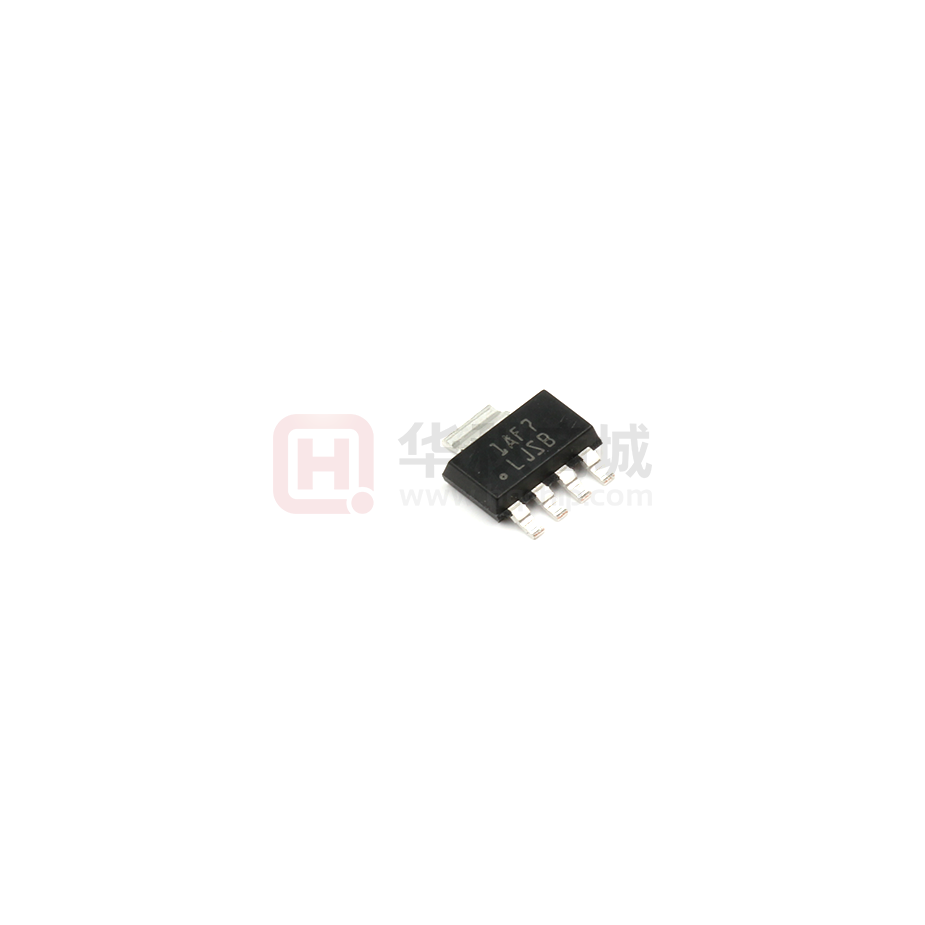
LJSB
LP38692MP-3.3/NOPB
ACTIVE
SOT-223
NDC
5
1000
RoHS & Green
SN
Level-1-260C-UNLIM
-40 to 125
LJSB
LP38692MP-5.0
NRND
SOT-223
NDC
5
1000
Non-RoHS
& Green
Call TI
Level-1-260C-UNLIM
-40 to 125
LJTB
LP38692MP-5.0/NOPB
ACTIVE
SOT-223
NDC
5
1000
RoHS & Green
SN
Level-1-260C-UNLIM
-40 to 125
LJTB
Samples
LP38692MPX-1.8/NOPB
ACTIVE
SOT-223
NDC
5
2000
RoHS & Green
SN
Level-1-260C-UNLIM
-40 to 125
LJPB
Samples
LP38692MPX-3.3/NOPB
ACTIVE
SOT-223
NDC
5
2000
RoHS & Green
SN
Level-1-260C-UNLIM
-40 to 125
LJSB
Samples
LP38692MPX-5.0/NOPB
ACTIVE
SOT-223
NDC
5
2000
RoHS & Green
SN
Level-1-260C-UNLIM
-40 to 125
LJTB
Samples
LP38692SD-1.8/NOPB
ACTIVE
WSON
NGG
6
1000
RoHS & Green
SN
Level-1-260C-UNLIM
-40 to 125
L123B
Samples
LP38692SD-2.5/NOPB
ACTIVE
WSON
NGG
6
1000
RoHS & Green
SN
Level-1-260C-UNLIM
-40 to 125
L124B
Samples
LP38692SD-3.3/NOPB
ACTIVE
WSON
NGG
6
1000
RoHS & Green
SN
Level-1-260C-UNLIM
-40 to 125
L125B
Samples
LP38692SD-5.0/NOPB
ACTIVE
WSON
NGG
6
1000
RoHS & Green
SN
Level-1-260C-UNLIM
-40 to 125
L126B
Samples
LP38692SDX-3.3/NOPB
ACTIVE
WSON
NGG
6
4500
RoHS & Green
SN
Level-1-260C-UNLIM
-40 to 125
L125B
Samples
LP38692SDX-5.0/NOPB
ACTIVE
WSON
NGG
6
4500
RoHS & Green
SN
Level-1-260C-UNLIM
-40 to 125
L126B
Samples
(1)
The marketing status values are defined as follows:
ACTIVE: Product device recommended for new designs.
LIFEBUY: TI has announced that the device will be discontinued, and a lifetime-buy period is in effect.
NRND: Not recommended for new designs. Device is in production to support existing customers, but TI does not recommend using this part in a new design.
PREVIEW: Device has been announced but is not in production. Samples may or may not be available.
OBSOLETE: TI has discontinued the production of the device.
(2)
RoHS: TI defines "RoHS" to mean semiconductor products that are compliant with the current EU RoHS requirements for all 10 RoHS substances, including the requirement that RoHS substance
do not exceed 0.1% by weight in homogeneous materials. Where designed to be soldered at high temperatures, "RoHS" products are suitable for use in specified lead-free processes. TI may
reference these types of products as "Pb-Free".
RoHS Exempt: TI defines "RoHS Exempt" to mean products that contain lead but are compliant with EU RoHS pursuant to a specific EU RoHS exemption.
Addendum-Page 2
Samples
Samples
�PACKAGE OPTION ADDENDUM
www.ti.com
27-Jul-2022
Green: TI defines "Green" to mean the content of Chlorine (Cl) and Bromine (Br) based flame retardants meet JS709B low halogen requirements of


 工商网监
湘ICP备2023018690号
工商网监
湘ICP备2023018690号