LP5910
LP5910
SNVSA91F – SEPTEMBER 2015 – REVISED APRIL
2021
SNVSA91F – SEPTEMBER 2015 – REVISED APRIL 2021
www.ti.com
LP5910 300-mA Low-Noise, Low-IQ LDO
1 Features
3 Description
•
•
•
•
•
•
•
•
•
•
•
•
•
The LP5910 is a low-noise LDO that can supply
up to 300 mA of output current. Designed to meet
the requirements of RF and analog circuits, this
device provides low noise, high PSRR, low quiescent
current, and superior line transient and load transient
response. Using new innovative design techniques
the LP5910 offers class-leading noise performance
without a noise bypass capacitor and with the option
for remote output capacitor placement.
Input voltage range: 1.3 V to 3.3 V
Output voltage range: 0.8 V to 2.3 V
Output current: 300 mA
PSRR: 75 dB at 1 kHz
Output voltage tolerance: ±2%
Low dropout: 120 mV (typical)
Very low IQ (enabled, no load): 12 µA
Low output-voltage noise: 12 µVRMS
Stable with ceramic input and output capacitors
Thermal overload protection
Short-circuit protection
Reverse current protection
Automatic output discharge for fast turnoff
2 Applications
•
•
•
•
•
•
•
The device contains a reverse current protection
circuit that prevents a reverse current flow through the
LDO to the IN pin when the input voltage is lower than
the output voltage.
When the Enable (EN) pin is low, and the output is
in an OFF state, an automatic output discharge circuit
discharges the output capacitance for fast turnoff.
Mobile phones and tablets
Digital cameras and audio devices
Portable and battery-powered equipment
Portable medical equipment
Virtual reality
RF, PLL, VCO, and clock power supplies
IP cameras
With its low input and low output voltage range the
LP5910 is well-suited as a post DC-DC regulator
(post BUCK regulator) or for single- or dual-cell
applications.
The device is designed to work with a 1-μF input and
a 1-μF output ceramic capacitor. A separate noise
bypass capacitor is not required.
This device is available with fixed output voltages
from 0.8 V to 2.3 V in 25-mV steps. Contact Texas
Instruments Sales for specific voltage option needs.
Device Information(1)
PART NUMBER
LP5910
(1)
PACKAGE
BODY SIZE
WSON (6)
2.00 mm × 2.00 mm (NOM)
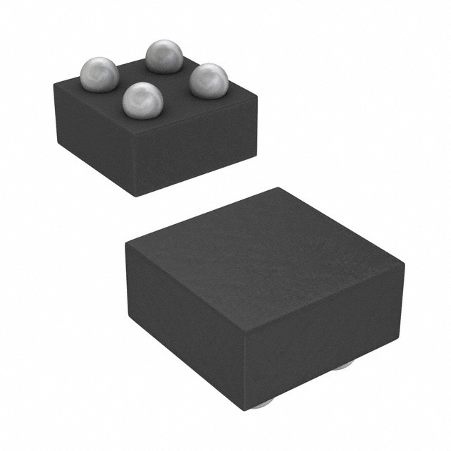
DSBGA (4)
0.742 mm × 0.742 mm (MAX)
For all available packages, see the orderable addendum at
the end of the data sheet.
VIN
VOUT
IN
OUT
CIN
COUT
LP5910
Enable
EN
GND
Simplified Schematic
An©IMPORTANT
NOTICEIncorporated
at the end of this data sheet addresses availability, warranty, changes, use in
safety-critical
applications,
Copyright
2021 Texas Instruments
Submit
Document
Feedback
intellectual property matters and other important disclaimers. PRODUCTION DATA.
Product Folder Links: LP5910
1
�LP5910
www.ti.com
SNVSA91F – SEPTEMBER 2015 – REVISED APRIL 2021
Table of Contents
1 Features............................................................................1
2 Applications..................................................................... 1
3 Description.......................................................................1
4 Revision History.............................................................. 2
5 Pin Configuration and Functions...................................3
6 Specifications.................................................................. 4
6.1 Absolute Maximum Ratings........................................ 4
6.2 ESD Ratings............................................................... 4
6.3 Recommended Operating Conditions.........................4
6.4 Thermal Information....................................................5
6.5 Electrical Characteristics.............................................5
6.6 Typical Characteristics................................................ 7
7 Detailed Description...................................................... 11
7.1 Overview................................................................... 11
7.2 Functional Block Diagram......................................... 11
7.3 Feature Description...................................................11
7.4 Device Functional Modes..........................................12
8 Applications and Implementation................................ 13
8.1 Application Information............................................. 13
8.2 Typical Application.................................................... 13
9 Power Supply Recommendations................................17
10 Layout...........................................................................18
10.1 Layout Guidelines................................................... 18
10.2 Layout Examples.................................................... 18
11 Device and Documentation Support..........................19
11.1 Documentation Support.......................................... 19
11.2 Receiving Notification of Documentation Updates.. 19
11.3 Support Resources................................................. 19
11.4 Trademarks............................................................. 19
11.5 Electrostatic Discharge Caution.............................. 19
11.6 Glossary.................................................................. 19
4 Revision History
NOTE: Page numbers for previous revisions may differ from page numbers in the current version.
Changes from Revision E (July 2017) to Revision F (April 2021)
Page
• Updated the numbering format for tables, figures, and cross-references throughout the document .................1
• Deleted WEBENCH links from document...........................................................................................................1
• Deleted last bullet from Features section........................................................................................................... 1
• Changed Dropout Voltage specifications for 1.5V ≤ VIN < 1.8V; added new rows in Dropout Voltage
specifications for this voltage range....................................................................................................................5
• Deleted Custom Design With WEBENCH® Tools section from Detailed Design Procedure ...........................13
• Deleted Custom Design With WEBENCH® Tools section from Documentation Support ................................19
Changes from Revision D (August 2016) to Revision E (July 2017)
Page
• Added new package, YKA0004-C01 associated with orderables LP5910-1.1BYKAR and LP5910-1.1BYKAT;
added links for WEBENCH................................................................................................................................. 1
2
Submit Document Feedback
Copyright © 2021 Texas Instruments Incorporated
Product Folder Links: LP5910
�LP5910
www.ti.com
SNVSA91F – SEPTEMBER 2015 – REVISED APRIL 2021
5 Pin Configuration and Functions
IN
A1
OUT
A2
OUT
A2
IN
A1
B1
EN
B2
GND
B2
GND
B1
EN
Figure 5-1. YKA Package, 4-Pin Ultra-Thin DSBGA, Figure 5-2. YKA Package, 4-Pin Ultra-Thin DSBGA,
Top View
Bottom View
OUT
1
6
IN
NC
2
5
GND
NC
3
4
EN
Figure 5-3. DRV Package, 6-Pin WSON With Thermal Pad, Top View
Table 5-1. Pin Functions
PIN
I/O
DESCRIPTION
4
I
Enable input; disables the regulator when logic low. Enables the regulator when logic
high. An internal 1-MΩ pull down resistor connects this input to ground.
B2
5
—
A1
6
I
NC
—
2, 3
—
No internal connection. Connect to ground or leave open.
OUT
A2
1
O
Voltage output. A 1-µF low-ESR capacitor must be connected from this pin to the
GND pin. Connect this output to the load circuit.
Exposed Pad
—
Thermal Pad
—
The exposed thermal pad on the bottom of the package must be connected to a
copper area under the package on the PCB. Connect to ground potential or leave
floating. Do not connect to any potential other than the same ground potential seen at
device pin 5 (GND). See the Power Dissipation section for more information.
NAME
DSBGA
WSON
EN
B1
GND
IN
Common ground
Voltage supply input. A 1-μF capacitor must be connected at this input.
Submit Document Feedback
Copyright © 2021 Texas Instruments Incorporated
Product Folder Links: LP5910
3
�LP5910
www.ti.com
SNVSA91F – SEPTEMBER 2015 – REVISED APRIL 2021
6 Specifications
6.1 Absolute Maximum Ratings
over operating free-air temperature range (unless otherwise noted)(1) (2)
MIN
MAX
UNIT
Input voltage, VIN
–0.3
3.6
V
Output voltage, VOUT
–0.3
3.6
V
Enable input voltage, VEN
–0.3
3.6
V
150
°C
150
°C
Continuous power dissipation(3)
Internally limited
Junction temperature, TJ(MAX)
Storage temperature, Tstg
(1)
(2)
(3)
–65
W
Stresses beyond those listed under Absolute Maximum Ratings may cause permanent damage to the device. These are stress ratings
only, and functional operation of the device at these or any other conditions beyond those indicated under Recommended Operating
Conditions is not implied. Exposure to absolute-maximum-rated conditions for extended periods may affect device reliability.
All voltages are with respect to the GND pin.
Internal thermal shutdown circuitry protects the device from permanent damage.
6.2 ESD Ratings
VALUE
V(ESD)
(1)
(2)
Electrostatic discharge
Human-body model (HBM), per ANSI/ESDA/JEDEC JS-001(1)
±1000
Charged-device model (CDM), per JEDEC specification JESD22-C101(2)
±250
UNIT
V
JEDEC document JEP155 states that 500-V HBM allows safe manufacturing with a standard ESD control process.
JEDEC document JEP157 states that 250-V CDM allows safe manufacturing with a standard ESD control process.
6.3 Recommended Operating Conditions
over operating free-air temperature range (unless otherwise noted)(1)
MIN
UNIT
Input voltage, VIN
1.3
3.3
V
Output voltage, VOUT
0.8
2.3
V
Enable input voltage, VEN
0
3.3
V
Output current, IOUT
0
300
mA
Junction temperature, TJ (1)
–40
125
°C
Ambient temperature, TA (1)
–40
85
°C
(1)
4
MAX
The maximum ambient temperature, (TA(MAX)) is a recommended value only and can vary depending on device power dissipation and
RθJA. For reliable operation, the junction temperature (TJ) must be limited to a maximum of 125°C. Ambient temperature (TA), thermal
resistance (RθJA) , VIN, VOUT, and IOUT all define TJ : TJ = TA + (RθJA × ((VIN – VOUT) × IOUT).
Submit Document Feedback
Copyright © 2021 Texas Instruments Incorporated
Product Folder Links: LP5910
�LP5910
www.ti.com
SNVSA91F – SEPTEMBER 2015 – REVISED APRIL 2021
6.4 Thermal Information
LP5910
THERMAL
METRIC(1)
UNIT
YKA (DSBGA)
DRV (WSON)
4 PINS
6 PINS
202.8
79.2(3)
°C/W
RθJA (2)
Junction-to-ambient thermal resistance, High-K
RθJC(top)
Junction-to-case (top) thermal resistance
3.3
110.2
°C/W
RθJB
Junction-to-board thermal resistance
36.0
48.7
°C/W
ψJT
Junction-to-top characterization parameter
0.4
5.2
°C/W
ψJB
Junction-to-board characterization parameter
36.0
49.1
°C/W
RθJC(bot)
Junction-to-case (bottom) thermal resistance
n/a
18.1
°C/W
(1)
(2)
(3)
For more information about traditional and new thermal metrics, see the Semiconductor and IC Package Thermal Metrics application
report.
Thermal resistance value RθJA is based on the EIA/JEDEC High-K printed circuit board defined by: JESD51-7 - High Effective Thermal
Conductivity Test Board for Leaded Surface Mount Packages.
The PCB for the WSON/DRV package RθJA includes two (2) thermal vias under the exposed thermal pad per EIA/JEDEC JESD51-5.
6.5 Electrical Characteristics
VIN = VOUT(NOM) + 0.5 V, VEN = 1 V, IOUT = 1 mA, CIN = 1 µF, and COUT = 1 µF (unless otherwise noted)(1) (2) (3)
PARAMETER
TEST CONDITIONS
MIN
Output voltage tolerance
VIN = (VOUT(NOM) + 0.5 V) to 3.3 V,
IOUT = 1 mA to 300 mA
–2
ΔVOUT
Line regulation
VIN = (VOUT(NOM) + 0.5 V) to 3.3 V,
IOUT = 1 mA
Load regulation
IOUT = 1 mA to 300 mA
ILOAD
Load current
See(4)
IQ
Quiescent current(5)
IQ(SD)
Quiescent current in
shutdown(5)
IRO
Output reverse current(7)
VOUT > VIN
VOUT = 3.3 V, VIN = VEN = 0 V
IG
Ground current(6)
IOUT = 0 mA (VOUT = 2.3 V)
TYP
MAX
UNIT
GENERAL
VDO
ILIMIT
Dropout
voltage(8)
Output current limit
2
0.01
%/V
0.002
0
VEN = 1 V, IOUT = 0 mA
%/mA
300
12
25
VEN = 1 V, IOUT = 300 mA
230
350
VEN = 0.3 V, –40°C ≤ TJ ≤ 85°C
0.02
2
VOUT = 3.3 V, VIN = VEN = 1.3 V
%VOUT
mA
µA
–20
0
µA
0
50
µA
15
µA
1.3 V ≤ VOUT < 1.5 V,
IOUT = 300 mA
DSBGA only
200
300
1.5 V ≤ VOUT VIH to VOUT = 95% of VOUT(NOM)
80
200
µs
OUTPUT DISCHARGE
RAD
(1)
(2)
Output discharge pulldown
resistance
VEN = 0 V, VIN = 2.3 V
160
Ω
All voltages are with respect to the device GND pin.
Minimum and maximum limits are ensured through test, design, or statistical correlation over the TJ range of –40°C to 125°C, unless
otherwise stated. Typical values represent the most likely parametric norm at TA = 25°C, and are provided for reference purposes only.
CIN, COUT: Low-ESR Surface-Mount-Ceramic Capacitors (MLCCs) used in setting electrical characteristics.
The device maintains a stable, regulated output voltage without a load current.
Quiescent current is defined here as the difference in current between the input voltage source and the load at VOUT. IQ = (IIN – IOUT)
Ground current is defined here as the total current flowing to ground as a result of all input voltages applied to the device.
Output reverse current (IRO) is measured at the IN pin.
Dropout voltage is the voltage difference between the input and the output at which the output voltage drops to 100 mV below its
nominal value. Dropout voltage is not a valid condition for output voltages less than 1.3 V as compliance with the minimum operating
input voltage can not be ensured.
(9) There is a 1-MΩ resistor between EN and ground on the device.
(10) This specification is verified by design.
(3)
(4)
(5)
(6)
(7)
(8)
6
Submit Document Feedback
Copyright © 2021 Texas Instruments Incorporated
Product Folder Links: LP5910
�LP5910
www.ti.com
SNVSA91F – SEPTEMBER 2015 – REVISED APRIL 2021
6.6 Typical Characteristics
VOUT = 1.8 V, VIN = VOUT + 0.5 V, VEN = VIN, IOUT = 1 mA, CIN = 1 µF, COUT = 1 µF, TJ = 25°C (unless otherwise noted)
1.2
1.2
ON (VIH)
OFF (VIL)
1.1
1
VEN Thresholds (V)
1
Enable Threshold (V)
ON (VIH)
OFF (VIL)
1.1
0.9
0.8
0.7
0.6
0.5
0.9
0.8
0.7
0.6
0.5
0.4
0.4
0.3
0.3
0.2
-50
0.2
-25
0
25
50
75
Junction Temperature (°C)
VIN = 2.3 V
100
1
125
1.5
3
3.5
D002
VOUT = 1.8 V
Figure 6-2. VEN Thresholds vs VIN
1.2
1.2
ON (VIH)
OFF (VIL)
1.1
ON (VIH)
OFF (VIL)
1.1
1
VEN Thresholds (V)
1
VEN Thresholds (V)
2.5
VIN (V)
Figure 6-1. VEN Threshold vs Temperature
0.9
0.8
0.7
0.6
0.5
0.9
0.8
0.7
0.6
0.5
0.4
0.4
0.3
0.3
0.2
0.2
1
1.5
2
2.5
3
1
3.5
VIN (V)
1.5
2
2.5
3
3.5
VIN (V)
D003
D004
TJ = 125°C
TJ = –40°C
Figure 6-4. VEN Thresholds vs VIN
Figure 6-3. VEN Thresholds vs VIN
2
2
1.8
1.8
1.6
1.6
1.4
1.4
1.2
1.2
VOUT (V)
VOUT (V)
2
D001
1
0.8
0.6
1
0.8
0.6
0.4
0.4
18 k: (100 µA)
1.8 k: (1 mA)
180 : (10 mA)
0.2
180 : (10 mA)
18 : (100 mA)
6 : (300 mA)
0.2
0
0
0
0.5
1
1.5
2
VIN (V)
VEN = VIN
2.5
3
3.5
0
0.5
D005
1
1.5
2
VIN (V)
2.5
3
3.5
D006
VEN = VIN
Figure 6-5. VOUT vs VIN
Figure 6-6. VOUT vs VIN
Submit Document Feedback
Copyright © 2021 Texas Instruments Incorporated
Product Folder Links: LP5910
7
�LP5910
www.ti.com
SNVSA91F – SEPTEMBER 2015 – REVISED APRIL 2021
6.6 Typical Characteristics (continued)
VOUT = 1.8 V, VIN = VOUT + 0.5 V, VEN = VIN, IOUT = 1 mA, CIN = 1 µF, COUT = 1 µF, TJ = 25°C (unless otherwise noted)
25
25
125°C
85°C
25°C
-40°C
20
IQ [No Load] (µA)
IQ [No Load] (µA)
20
125°C
85°C
25°C
-40°C
15
10
5
15
10
5
0
0
0
0.5
1
1.5
2
VIN (V)
VOUT = 0.8 V
2.5
3
3.5
0
0.5
VEN = VIN
3
3.5
D008
VEN = VIN
No load
25
125°C
85°C
25°C
-40°C
125°C
85°C
25°C
-40°C
20
IQ [No Load] (µA)
20
IQ [No Load] (µA)
2.5
Figure 6-8. IQ vs VIN
25
15
10
5
15
10
5
0
0
0
0.5
1
1.5
2
VIN (V)
VOUT = 1.8 V
2.5
3
3.5
0
0.5
VEN = VIN
No load
-10
-20
-20
-30
-30
PSRR (dB)
-10
-40
-50
-60
3.5
D010
VEN = VIN
No load
-50
-60
-70
-80
-80
-90
-90
-100
10
-100
10
10k
100k
Frequency (Hz)
VIN = 1.3 V
3
-40
-70
VOUT = 0.8 V
2.5
Figure 6-10. IQ vs VIN
0
1k
1.5
2
VIN (V)
VOUT = 2.3 V
0
100
1
D009
Figure 6-9. IQ vs VIN
PSRR (dB)
1.5
2
VIN (V)
VOUT = 1.2 V
No load
Figure 6-7. IQ vs VIN
1M
10M
100
D011
IOUT = 20 mA
VOUT = 1.8 V
1k
10k
100k
Frequency (Hz)
VIN = 2.3 V
1M
10M
D012
IOUT = 20 mA
Figure 6-12. PSRR vs Frequency
Figure 6-11. PSRR vs Frequency
8
1
D007
Submit Document Feedback
Copyright © 2021 Texas Instruments Incorporated
Product Folder Links: LP5910
�LP5910
www.ti.com
SNVSA91F – SEPTEMBER 2015 – REVISED APRIL 2021
6.6 Typical Characteristics (continued)
0
0.5
-10
0.45
-20
0.4
-30
0.35
Noise (µV / —Hz)
PSRR (dB)
VOUT = 1.8 V, VIN = VOUT + 0.5 V, VEN = VIN, IOUT = 1 mA, CIN = 1 µF, COUT = 1 µF, TJ = 25°C (unless otherwise noted)
-40
-50
-60
-70
0.3
0.25
0.2
0.15
-80
0.1
-90
0.05
-100
10
100
1k
VOUT = 2.3 V
10k
100k
Frequency (Hz)
VIN = 2.8 V
1M
0
10
10M
1 mA
300 mA
100
D013
1000
10000
Frequency (Hz)
VOUT = 0.8 V
IOUT = 20 mA
100000
1000000
D014
VIN = 1.3 V
Figure 6-14. Noise Density
Figure 6-13. PSRR vs Frequency
1.5
0.5
1 mA
300 mA
0.45
1.25
1
0.4
0.35
0.5
'VOUT (%)
Noise (µV / —Hz)
0.75
0.3
0.25
0.2
0
-0.25
-0.5
0.15
-0.75
0.1
-1
0.05
0
10
0.25
-1.25
100
1000
10000
Frequency (Hz)
VOUT = 2.3 V
100000
-1.5
-50
1000000
VIN = 2.8 V
0
25
50
75
Junction Temperature (°C)
VIN = VOUT + 0.5 V
Figure 6-15. Noise Density
100
125
D016
IOUT = 1 mA
Figure 6-16. ΔVOUT vs Temperature
250
250
VIN = 3.3 V
VIN = 1.3 V
225
VIN = 3.3 V
VIN = 2.3 V
225
200
200
175
175
150
150
IGND (µA)
IGND (µA)
-25
D015
125
100
125
100
75
75
50
50
25
25
0
0
0
50
100
150
IOUT (mA)
200
VOUT = 0.8 V
250
300
0
50
D017
100
150
IOUT (mA)
200
250
300
D018
VOUT = 1.8 V
Figure 6-17. IGND vs IOUT
Figure 6-18. IGND vs IOUT
Submit Document Feedback
Copyright © 2021 Texas Instruments Incorporated
Product Folder Links: LP5910
9
�LP5910
www.ti.com
SNVSA91F – SEPTEMBER 2015 – REVISED APRIL 2021
6.6 Typical Characteristics (continued)
VOUT = 1.8 V, VIN = VOUT + 0.5 V, VEN = VIN, IOUT = 1 mA, CIN = 1 µF, COUT = 1 µF, TJ = 25°C (unless otherwise noted)
250
300
VIN = 3.3 V
VIN = 2.8 V
225
250
200
175
200
150
VDO (mV)
IGND (µA)
VOUT = 1.2 V
VOUT = 1.8 V
VOUT = 2.3 V
125
100
150
100
75
50
50
25
0
0
0
50
100
150
IOUT (mA)
200
250
300
0
50
100
D019
150
IOUT (mA)
200
250
300
D020
VOUT = 2.3 V
Figure 6-20. Dropout Voltage vs IOUT
2.5
2.5
1.5
1.5
1
1
0.5
IOUT (mA)
2
VOUT (V)
0.5
0
25
VEN = VIN
50
75
Time (µs)
100
0
150
125
100
8
80
4
60
0
40
-4
20
VIN
VOUT
0
-25
12
IOUT
'VOUT
0
-20
-10
0
10
D021
VOUT = 1.8 V
COUT = 1 µF
VIN = 2.3 V
20
30
40
Time (µs)
50
D022
COUT = 1 µF
tRISE = 10 µs
12
8
2.5
8
80
4
2.0
4
60
0
1.5
0
40
-4
1.0
-4
20
-8
0.5
-12
80
0.0
IOUT
'VOUT
0
-20
-10
0
10
20
30
40
Time (µs)
VIN = 2.3 V
VOUT = 1.8 V
IOUT = 100 mA to 1 mA
tFALL = 10 µs
50
60
70
VIN (V)
3.0
'VOUT (mV)
12
100
IOUT (mA)
-12
80
Figure 6-22. Load Transient Response
120
VIN (V)
'VOUT (mV)
0
50
100
D023
COUT = 1 µF
150
200 250 300
Time (Ps)
ΔVIN = 0.5 V
VOUT = 1.8 V
tRISE = tFALL = 30 µs
IOUT = 1 mA
Figure 6-23. Load Transient Response
10
70
VOUT = 1.8 V
IOUT = 1 mA to 100 mA
Figure 6-21. Turnon Time
60
-8
Submit Document Feedback
350
400
450
'VOUT (mV)
VIN (V)
2
120
'VOUT (mV)
Figure 6-19. IGND vs IOUT
-8
-12
500
D024
COUT = 1 µF
Figure 6-24. Line Transient Response
Copyright © 2021 Texas Instruments Incorporated
Product Folder Links: LP5910
�LP5910
www.ti.com
SNVSA91F – SEPTEMBER 2015 – REVISED APRIL 2021
7 Detailed Description
7.1 Overview
The LP5910 is a linear regulator capable of supplying 300-mA output current. Designed to meet the
requirements of RF and analog circuits, the LP5910 device provides low noise, high PSRR, low quiescent
current, and low line/load transient response figures. Using new innovative design techniques the LP5910 offers
class-leading noise performance without a noise bypass capacitor and the option for remote output capacitor
placement.
7.2 Functional Block Diagram
Current
limit
IN
OUT
VIN
EA
Bandgap
Output
discharge
EN
EN
Control
GND
7.3 Feature Description
7.3.1 No-Load Stability
The LP5910 remains stable and in regulation with no external load.
7.3.2 Thermal Overload Protection
The LP5910 contains a thermal shutdown protection circuit to turn off the output current when excessive heat
is dissipated in the LDO. Thermal shutdown occurs when the thermal junction temperature (TJ) of the main
pass-FET exceeds 160°C (typical). Thermal shutdown hysteresis assures that the LDO again resets (turns on)
when the temperature falls to 145°C (typical).
7.3.3 Short-Circuit Protection
The LP5910 contains internal current limit which reduces output current to a safe value if the output is
overloaded or shorted. Depending upon the value of VIN, thermal limiting may also become active as the
average power dissipated causes the die temperature to increase to the limit value (about 160°C). The
hysteresis of the thermal shutdown circuitry can result in a cyclic behavior on the output as the die temperature
heats and cools.
7.3.4 Output Automatic Discharge
The LP5910 output employs an internal 160-Ω (typical) pulldown resistance to discharge the output when the EN
pin is low, and the device is disabled.
7.3.5 Reverse Current Protection
The device contains a reverse current protection circuit that prevents a backward current flowing through the
LDO from the OUT pin to the IN pin.
Submit Document Feedback
Copyright © 2021 Texas Instruments Incorporated
Product Folder Links: LP5910
11
�LP5910
www.ti.com
SNVSA91F – SEPTEMBER 2015 – REVISED APRIL 2021
7.4 Device Functional Modes
7.4.1 Enable (EN)
The LP5910 may be switched to the ON or OFF state by logic input at the EN pin. A logic-high voltage on the EN
pin turns the device to the ON state. A logic-low voltage on the EN pin turns the device to the OFF state. If the
application does not require the shutdown feature, the EN pin must be tied to VIN to keep the regulator output
permanently in the ON state when power is applied
To ensure proper operation, the signal source used to drive the EN input must be able to swing above and below
the specified turnon or turnoff voltage thresholds listed in the Electrical Characteristics section under VIL and VIH.
A 1-MΩ pulldown resistor ties the EN input to ground. If the EN pin is left open, the internal 1-MΩ pulldown
resistor ensures that the device is turned into an OFF state by default.
When the EN pin is low, and the output is in an OFF state, the output activates an internal pulldown resistance to
discharge the output capacitance for fast turnoff.
12
Submit Document Feedback
Copyright © 2021 Texas Instruments Incorporated
Product Folder Links: LP5910
�LP5910
www.ti.com
SNVSA91F – SEPTEMBER 2015 – REVISED APRIL 2021
8 Applications and Implementation
Note
Information in the following applications sections is not part of the TI component specification,
and TI does not warrant its accuracy or completeness. TI’s customers are responsible for
determining suitability of components for their purposes, as well as validating and testing their design
implementation to confirm system functionality.
8.1 Application Information
The LP5910 is designed to meet the requirements of RF and analog circuits, by providing low noise, high
PSRR, low quiescent current, and low line or load transient response figures. The device offers excellent noise
performance without the need for a noise bypass capacitor and is stable with input and output capacitors with
a value of 1 µF. The LP5910 delivers this performance in an industry-standard DSBGA package which, for this
device, is specified with a TJ of –40°C to +125°C.
8.2 Typical Application
Figure 8-1 shows the typical application circuit for the LP5910. Input and output capacitances may need to be
increased above 1-µF minimum for some applications.
VIN
VOUT
IN
OUT
1 µF
1 µF
LP5910
Enable
EN
GND
Figure 8-1. LP5910 Typical Application
8.2.1 Design Requirements
For typical LP5910 applications, use the parameters listed in Table 8-1.
Table 8-1. Design Parameters
DESIGN PARAMETER
EXAMPLE VALUE
Input voltage
1.3 V to 3.3 V
Output voltage
0.8 V to 2.3 V
Output current
300 mA
Output capacitor range
1 µF to 10 µF
8.2.2 Detailed Design Procedure
8.2.2.1 External Capacitors
Like most low-dropout regulators, the LP5910 requires external capacitors for regulator stability. The device is
specifically designed for portable applications requiring minimum board space and smallest components. These
capacitors must be correctly selected for good performance.
8.2.2.2 Input Capacitor
An input capacitor is required for stability. It is recommended that a 1-µF capacitor be connected from the
LP5910 IN pin to ground. (This capacitance value may be increased without limit.) The input capacitor must be
Submit Document Feedback
Copyright © 2021 Texas Instruments Incorporated
Product Folder Links: LP5910
13
�LP5910
www.ti.com
SNVSA91F – SEPTEMBER 2015 – REVISED APRIL 2021
located a distance of not more than 1 cm from the IN pin and returned to a clean analog ground. Any good
quality ceramic, tantalum, or film capacitor may be used at the input.
Note
Tantalum capacitors can suffer catastrophic failures due to surge current when connected to a lowimpedance source of power (like a battery or a very large capacitor). If a tantalum capacitor is used
at the input, it must be guaranteed by the manufacturer to have a surge current rating sufficient for
the application. There are no requirements for the equivalent series resistance (ESR) on the input
capacitor, but tolerance and temperature coefficient must be considered when selecting the capacitor
to ensure the capacitance remains 1 µF ±30% over the entire operating temperature range.
8.2.2.3 Output Capacitor
For capacitance values in the range of 1 µF to 4.7 µF, ceramic capacitors are the smallest, least expensive
and have the lowest ESR values, thus making them best for eliminating high frequency noise. The ESR of a
typical 1-µF ceramic capacitor is in the range of 20 mΩ to 40 mΩ, which easily meets the ESR requirement for
stability for the LP5910. The temperature performance of ceramic capacitors varies by type. Most large value
ceramic capacitors ( ≥ 2.2 µF) are manufactured with Z5U or Y5V temperature characteristics, which results in
the capacitance dropping by more than 50% as the temperature goes from 25°C to 85°C.
A better choice for temperature coefficient in a ceramic capacitor is X7R. This type of capacitor is the
most stable and holds the capacitance within ±15% over the temperature range. Tantalum capacitors are
less desirable than ceramic for use as output capacitors because they are more expensive when comparing
equivalent capacitance and voltage ratings in the 1-µF to 4.7-µF range.
8.2.2.4 Capacitor Characteristics
The LP5910 is designed to work with ceramic capacitors on the input and output to take advantage of the
benefits they offer. For capacitance values in the range of 1 µF to 10 µF, ceramic capacitors are the smallest,
least expensive and have the lowest ESR values, thus making them best for eliminating high frequency noise.
The ESR of a typical 1-µF ceramic capacitor is in the range of 20 mΩ to 40 mΩ, which easily meets the ESR
requirement for stability for the LP5910.
A better choice for temperature coefficient in a ceramic capacitor is X7R. This type of capacitor is the
most stable and holds the capacitance within ±15% over the temperature range. Tantalum capacitors are
less desirable than ceramic for use as output capacitors because they are more expensive when comparing
equivalent capacitance and voltage ratings in the 1-µF to 10-µF range.
Another important consideration is that tantalum capacitors have higher ESR values than equivalent size
ceramics. This means that while it may be possible to find a tantalum capacitor with an ESR value within
the stable range, it would have to be larger in capacitance (which means bigger and more costly) than a ceramic
capacitor with the same ESR value. Also, the ESR of a typical tantalum increases about 2:1 as the temperature
goes from 25°C down to –40°C, so some guard band must be allowed.
8.2.2.5 Remote Capacitor Operation
The LP5910 requires at least a 1-µF capacitor at the OUT pin, but there is no strict requirements about the
location of the capacitor in regards to the pin. In practical designs the output capacitor may be located up to
10 cm away from the LDO. This means that there is no need to have a special capacitor close to the OUT pin
if there is already respective capacitors in the system (like a capacitor at the input of supplied part). The remote
capacitor feature helps user to minimize the number of capacitors in the system.
As a good design practice, keep the wiring parasitic inductance at a minimum, using as wide as possible traces
from the LDO output to the capacitors, keeping the LDO output trace layer as close as possible to ground layer
and avoiding vias on the path. If there is a need to use vias, implement as many vias as possible between the
connection layers. It is recommended to keep parasitic wiring inductance less than 35 nH. For the applications
with fast load transients, an input capacitor is recommended, equal to or larger to the sum of the capacitance at
the output node, for the best load-transient performance.
14
Submit Document Feedback
Copyright © 2021 Texas Instruments Incorporated
Product Folder Links: LP5910
�LP5910
www.ti.com
SNVSA91F – SEPTEMBER 2015 – REVISED APRIL 2021
8.2.2.6 No-Load Stability
The LP5910 remains stable, and in regulation, with no external load.
8.2.2.7 Enable Control
The LP5910 may be switched to an ON or OFF state by a logic input at the EN pin. A voltage on this pin greater
than VIH turns the device on, while a voltage less than VIL turns the device off.
When the EN pin is low, the regulator output is off and the device typically consumes less than 1 µA. Additionally,
an output pulldown circuit is activated which ensures that any charge stored on COUT is discharged to ground.
If the application does not require the use of the shutdown feature, the EN pin can be tied directly to the IN pin to
keep the regulator output permanently on.
An internal 1-MΩ pulldown resistor ties the EN input to ground, ensuring that the device remains off if the EN pin
is left open circuit. To ensure proper operation, the signal source used to drive the EN pin must be able to swing
above and below the specified turn-on/off voltage thresholds listed in the Electrical Characteristics under VIL and
VIH.
Table 8-2. Recommended Output Capacitor Specification
PARAMETER
Output capacitor, COUT
TEST CONDITIONS
Capacitance for stability
ESR
MIN
NOM
0.7
1
5
MAX
UNIT
10
µF
500
mΩ
8.2.2.8 Power Dissipation
Knowing the device power dissipation and proper sizing of the thermal plane connected to the tab or pad is
critical to ensuring reliable operation. Device power dissipation depends on input voltage, output voltage, and
load conditions and can be calculated with Equation 1.
PD(MAX) = (VIN(MAX) – VOUT) × IOUT(MAX)
(1)
Power dissipation can be minimized, and greater efficiency can be achieved, by using the lowest available
voltage drop option that would still be greater than the dropout voltage (VDO). However, keep in mind that higher
voltage drops result in better dynamic (that is, PSRR and transient) performance.
On the WSON (DRV) package, the primary conduction path for heat is through the exposed power pad to the
PCB. To ensure the device does not overheat, connect the exposed pad, through thermal vias, to an internal
ground plane with an appropriate amount of copper PCB area .
On the DSBGA (YKA) package, the primary conduction path for heat is through the four bumps to the PCB.
The maximum allowable junction temperature (TJ(MAX)) determines maximum power dissipation allowed
(PD(MAX)) for the device package.
Power dissipation and junction temperature are most often related by the junction-to-ambient thermal resistance
(RθJA) of the combined PCB and device package and the temperature of the ambient air (TA), according to
Equation 2 or Equation 3:
TJ(MAX) = TA(MAX) + (RθJA × PD(MAX))
(2)
PD(MAX) = (TJ(MAX) - TA(MAX)) / RθJA
(3)
Unfortunately, this RθJA is highly dependent on the heat-spreading capability of the particular PCB design,
and therefore varies according to the total copper area, copper weight, and location of the planes. The RθJA
recorded in Thermal Information is determined by the specific EIA/JEDEC JESD51-7 standard for PCB and
copper-spreading area, and is to be used only as a relative measure of package thermal performance. For
a well-designed thermal layout, RθJA is actually the sum of the package junction-to-case (bottom) thermal
resistance (RθJCbot) plus the thermal resistance contribution by the PCB copper area acting as a heat sink.
Submit Document Feedback
Copyright © 2021 Texas Instruments Incorporated
Product Folder Links: LP5910
15
�LP5910
www.ti.com
SNVSA91F – SEPTEMBER 2015 – REVISED APRIL 2021
8.2.2.9 Estimating Junction Temperature
The EIA/JEDEC standard recommends the use of psi (Ψ) thermal characteristics to estimate the junction
temperatures of surface mount devices on a typical PCB board application. These characteristics are not true
thermal resistance values, but rather package specific thermal characteristics that offer practical and relative
means of estimating junction temperatures. These psi metrics are determined to be significantly independent of
copper-spreading area. The key thermal characteristics (ΨJT and ΨJB) are given in Thermal Information and are
used in accordance with Equation 4 or Equation 5.
TJ(MAX) = TTOP + (ΨJT × PD(MAX))
(4)
where
•
•
PD(MAX) is explained in Equation 1.
TTOP is the temperature measured at the center-top of the device package.
TJ(MAX) = TBOARD + (ΨJB × PD(MAX))
(5)
where
•
•
PD(MAX) is explained in Equation 1.
TBOARD is the PCB surface temperature measured 1-mm from the device package and centered on the
package edge.
For more information about the thermal characteristics ΨJT and ΨJB, see the Semiconductor and IC Package
Thermal Metrics application report, available for download at www.ti.com.
For more information about measuring TTOP and TBOARD, see the Using New Thermal Metrics application report,
available for download at www.ti.com.
For more information about the EIA/JEDEC JESD51 PCB used for validating RθJA, see the Thermal
Characteristics of Linear and Logic Packages Using JEDEC PCB Designs application report, available for
download at www.ti.com.
2.5
2.5
1.5
1.5
1
1
0.5
0.5
VIN
VOUT
0
-25
VEN = VIN
0
25
50
75
Time (µs)
100
VOUT = 1.8 V
125
0
150
IOUT (mA)
2
VOUT (V)
VIN (V)
2
120
12
100
8
80
4
60
0
40
-4
20
IOUT
'VOUT
0
-20
-10
0
D021
COUT = 1 µF
VIN = 2.3 V
IOUT = 1 mA to 100 mA
Figure 8-2. Turnon Time
16
10
20
30
40
Time (µs)
VOUT = 1.8 V
50
60
70
'VOUT (mV)
8.2.3 Application Curves
-8
-12
80
D022
COUT = 1 µF
tRISE = 10 µs
Figure 8-3. Load Transient Response
Submit Document Feedback
Copyright © 2021 Texas Instruments Incorporated
Product Folder Links: LP5910
�LP5910
www.ti.com
SNVSA91F – SEPTEMBER 2015 – REVISED APRIL 2021
9 Power Supply Recommendations
This device is designed to operate from an input supply voltage range of 1.3 V to 3.3 V. The input supply must
be well regulated and free of spurious noise. To ensure that the LP5910 output voltage is well regulated and
dynamic performance is optimum, the input supply must be at least VOUT + 0.5 V.
Submit Document Feedback
Copyright © 2021 Texas Instruments Incorporated
Product Folder Links: LP5910
17
�LP5910
www.ti.com
SNVSA91F – SEPTEMBER 2015 – REVISED APRIL 2021
10 Layout
10.1 Layout Guidelines
The dynamic performance of the LP5910 is dependant on the layout of the PCB. PCB layout practices that are
adequate for typical LDOs may degrade the PSRR, noise, or transient performance of the LP5910.
Best performance is achieved by placing CIN and COUT on the same side of the PCB as the LP5910 device, and
as close as is practical to the package. The ground connections for CIN and COUT must be back to the LP5910
GND pin using as wide and as short of a copper trace as is practical.
Avoid connections using long trace lengths, narrow trace widths, and/or connections through vias. These add
parasitic inductances and resistance that results in inferior performance especially during transient conditions.
10.1.1 DSBGA Mounting
The DSBGA package requires specific mounting techniques, which are detailed in the DSBGA Wafer Level Chip
Scale Package application note. For best results during assembly, alignment ordinals on the PC board may be
used to facilitate placement of the DSBGA device.
10.1.2 DSBGA Light Sensitivity
Exposing the DSBGA device to direct light may cause incorrect operation of the device. High intensity light
sources such as halogen lamps can affect electrical performance if they are situated in close proximity to the
device. The wavelengths that have the most detrimental effect are reds and infra-reds, which means that the
fluorescent lighting used inside most buildings has little effect on performance.
10.2 Layout Examples
OUT
A2
IN
A1
CIN
COUT
Via
B1
EN
B2
GND
Figure 10-1. LP5910 Typical DSBGA Layout
1
NC
2
NC
3
COUT
6
Thermal
Pad
OUT
IN
CIN
5
GND
4
EN
Figure 10-2. LP5910 Typical WSON Layout
18
Submit Document Feedback
Copyright © 2021 Texas Instruments Incorporated
Product Folder Links: LP5910
�LP5910
www.ti.com
SNVSA91F – SEPTEMBER 2015 – REVISED APRIL 2021
11 Device and Documentation Support
11.1 Documentation Support
11.1.1 Related Documentation
For related documentation, see the following:
•
•
•
•
Texas Instruments, AN-1112 DSBGA Wafer Level Chip Scale Package application note
Texas Instruments, Semiconductor and IC Package Thermal Metrics application report
Texas Instruments, Using New Thermal Metrics application report
Texas Instruments, Thermal Characteristics of Linear and Logic Packages Using JEDEC PCB Designs
application report
11.2 Receiving Notification of Documentation Updates
To receive notification of documentation updates, navigate to the device product folder on ti.com. Click on
Subscribe to updates to register and receive a weekly digest of any product information that has changed. For
change details, review the revision history included in any revised document.
11.3 Support Resources
TI E2E™ support forums are an engineer's go-to source for fast, verified answers and design help — straight
from the experts. Search existing answers or ask your own question to get the quick design help you need.
Linked content is provided "AS IS" by the respective contributors. They do not constitute TI specifications and do
not necessarily reflect TI's views; see TI's Terms of Use.
11.4 Trademarks
TI E2E™ is a trademark of Texas Instruments.
All trademarks are the property of their respective owners.
11.5 Electrostatic Discharge Caution
This integrated circuit can be damaged by ESD. Texas Instruments recommends that all integrated circuits be handled
with appropriate precautions. Failure to observe proper handling and installation procedures can cause damage.
ESD damage can range from subtle performance degradation to complete device failure. Precision integrated circuits may
be more susceptible to damage because very small parametric changes could cause the device not to meet its published
specifications.
11.6 Glossary
TI Glossary
This glossary lists and explains terms, acronyms, and definitions.
Mechanical, Packaging, and Orderable Information
The following pages include mechanical, packaging, and orderable information. This information is the most
current data available for the designated devices. This data is subject to change without notice and revision of
this document. For browser-based versions of this data sheet, refer to the left-hand navigation.
Submit Document Feedback
Copyright © 2021 Texas Instruments Incorporated
Product Folder Links: LP5910
19
�PACKAGE OPTION ADDENDUM
www.ti.com
24-Jun-2021
PACKAGING INFORMATION
Orderable Device
Status
(1)
Package Type Package Pins Package
Drawing
Qty
Eco Plan
(2)
Lead finish/
Ball material
MSL Peak Temp
Op Temp (°C)
Device Marking
(3)
(4/5)
(6)
LP5910-0.9YKAR
ACTIVE
DSBGA
YKA
4
3000
RoHS & Green
SNAGCU
Level-1-260C-UNLIM
-40 to 125
D
LP5910-1.0DRVR
ACTIVE
WSON
DRV
6
3000
RoHS & Green
NIPDAU
Level-1-260C-UNLIM
-40 to 125
59A
LP5910-1.0YKAR
ACTIVE
DSBGA
YKA
4
3000
RoHS & Green
SNAGCU
Level-1-260C-UNLIM
-40 to 125
A
LP5910-1.1BYKAR
ACTIVE
DSBGA
YKA
4
3000
RoHS & Green
SNAGCU
Level-1-260C-UNLIM
-40 to 125
T
LP5910-1.1BYKAT
ACTIVE
DSBGA
YKA
4
250
RoHS & Green
SNAGCU
Level-1-260C-UNLIM
-40 to 125
T
LP5910-1.1YKAR
ACTIVE
DSBGA
YKA
4
3000
RoHS & Green
SNAGCU
Level-1-260C-UNLIM
-40 to 125
E
LP5910-1.2YKAR
ACTIVE
DSBGA
YKA
4
3000
RoHS & Green
SNAGCU
Level-1-260C-UNLIM
-40 to 125
B
LP5910-1.725YKAR
ACTIVE
DSBGA
YKA
4
3000
RoHS & Green
SNAGCU
Level-1-260C-UNLIM
-40 to 125
N
LP5910-1.825YKAR
ACTIVE
DSBGA
YKA
4
3000
RoHS & Green
SNAGCU
Level-1-260C-UNLIM
-40 to 125
O
LP5910-1.825YKAT
ACTIVE
DSBGA
YKA
4
250
RoHS & Green
SNAGCU
Level-1-260C-UNLIM
-40 to 125
O
LP5910-1.8DRVR
ACTIVE
WSON
DRV
6
3000
RoHS & Green
NIPDAU
Level-1-260C-UNLIM
-40 to 125
59C
LP5910-1.8DRVT
ACTIVE
WSON
DRV
6
250
RoHS & Green
NIPDAU
Level-1-260C-UNLIM
-40 to 125
59C
LP5910-1.8YKAR
ACTIVE
DSBGA
YKA
4
3000
RoHS & Green
SNAGCU
Level-1-260C-UNLIM
-40 to 125
C
LP5910-1.8YKAT
ACTIVE
DSBGA
YKA
4
250
RoHS & Green
SNAGCU
Level-1-260C-UNLIM
-40 to 125
C
(1)
The marketing status values are defined as follows:
ACTIVE: Product device recommended for new designs.
LIFEBUY: TI has announced that the device will be discontinued, and a lifetime-buy period is in effect.
NRND: Not recommended for new designs. Device is in production to support existing customers, but TI does not recommend using this part in a new design.
PREVIEW: Device has been announced but is not in production. Samples may or may not be available.
OBSOLETE: TI has discontinued the production of the device.
(2)
RoHS: TI defines "RoHS" to mean semiconductor products that are compliant with the current EU RoHS requirements for all 10 RoHS substances, including the requirement that RoHS substance
do not exceed 0.1% by weight in homogeneous materials. Where designed to be soldered at high temperatures, "RoHS" products are suitable for use in specified lead-free processes. TI may
reference these types of products as "Pb-Free".
Addendum-Page 1
Samples
�PACKAGE OPTION ADDENDUM
www.ti.com
24-Jun-2021
RoHS Exempt: TI defines "RoHS Exempt" to mean products that contain lead but are compliant with EU RoHS pursuant to a specific EU RoHS exemption.
Green: TI defines "Green" to mean the content of Chlorine (Cl) and Bromine (Br) based flame retardants meet JS709B low halogen requirements of


 工商网监
湘ICP备2023018690号
工商网监
湘ICP备2023018690号
