Sample &
Buy
Product
Folder
Technical
Documents
Support &
Community
Tools &
Software
Reference
Design
OPA454
SBOS391B – DECEMBER 2007 – REVISED MARCH 2016
OPA454 High-Voltage (100-V), High-Current (50-mA)
Operational Amplifiers, G = 1 Stable
1 Features
3 Description
•
The OPA454 device is a low-cost operational
amplifier with high voltage (100 V) and relatively high
current drive (50 mA). It is unity-gain stable and has a
gain-bandwidth product of 2.5 MHz.
1
•
•
•
•
•
Wide Power-Supply Range:
±5 V (10 V) to ±50 V (100 V)
High-Output Load Drive: IO > ±50 mA
Wide Output Voltage Swing: 1 V to Rails
Independent Output Disable or Shutdown
Wide Temperature Range: –40°C to +85°C
8-Pin SO Package
2 Applications
•
•
•
•
•
•
•
•
Test Equipment
Avalanche Photodiode:
High-V Current Sense
Piezoelectric Cells
Transducer Drivers
Servo Drivers
Audio Amplifiers
High-Voltage Compliance Current Sources
General High-Voltage Regulators and Power
Simplified Pin Description
The OPA454 is internally protected against
overtemperature conditions and current overloads. It
is fully specified to perform over a wide power-supply
range of ±5 V to ±50 V or on a single supply of 10 V
to 100 V. The status flag is an open-drain output that
allows it to be easily referenced to standard lowvoltage logic circuitry. This high-voltage operational
amplifier provides excellent accuracy, wide output
swing, and is free from phase inversion problems that
are often found in similar amplifiers.
The output can be independently disabled using the
Enable or Disable Pin that has its own common
return pin to allow easy interface to low-voltage logic
circuitry. This disable is accomplished without
disturbing the input signal path, not only saving power
but also protecting the load.
Featured in a small exposed metal pad package, the
OPA454 is easy to heatsink over the extended
industrial temperature range, –40°C to +85°C.
Status
Flag
Device Information(1)
V+
PART NUMBER
Enable/Disable (E/D)
-IN
OPA454
VO
OPA454
PACKAGE
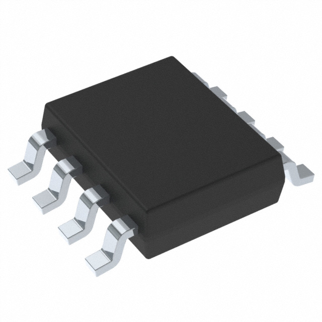
SO PowerPAD™ (8)
BODY SIZE (NOM)
4.89 mm × 3.90 mm
(1) For all available packages, see the orderable addendum at
the end of the data sheet.
+IN
Enable/Disable Common
(E/D Com)
V-
1
An IMPORTANT NOTICE at the end of this data sheet addresses availability, warranty, changes, use in safety-critical applications,
intellectual property matters and other important disclaimers. PRODUCTION DATA.
�OPA454
SBOS391B – DECEMBER 2007 – REVISED MARCH 2016
www.ti.com
Table of Contents
1
2
3
4
5
6
7
8
9
Features ..................................................................
Applications ...........................................................
Description .............................................................
Revision History.....................................................
Device Comparison Table.....................................
Pin Configuration and Functions .........................
Specifications.........................................................
1
1
1
2
3
3
4
7.1
7.2
7.3
7.4
7.5
7.6
4
4
4
4
5
7
Absolute Maximum Ratings ......................................
ESD Ratings ............................................................
Recommended Operating Conditions.......................
Thermal Information ..................................................
Electrical Characteristics: VS = ±50 V.......................
Typical Characteristics ..............................................
Parameter Measurement Information ................ 16
Detailed Description ............................................ 17
9.1
9.2
9.3
9.4
Overview .................................................................
Functional Block Diagram .......................................
Feature Description.................................................
Device Functional Modes........................................
17
17
18
21
10 Application and Implementation........................ 22
10.1 Applications Information........................................ 22
10.2 Typical Application ................................................ 24
10.3 System Examples ................................................. 27
11 Power Supply Recommendations ..................... 33
12 Layout................................................................... 33
12.1
12.2
12.3
12.4
12.5
Layout Guidelines .................................................
Layout Example ....................................................
Thermal Protection................................................
Power Dissipation .................................................
Heatsinking ...........................................................
33
35
36
36
37
13 Device and Documentation Support ................. 38
13.1
13.2
13.3
13.4
13.5
13.6
Device Support ....................................................
Documentation Support .......................................
Community Resources..........................................
Trademarks ...........................................................
Electrostatic Discharge Caution ............................
Glossary ................................................................
38
38
39
39
39
39
14 Mechanical, Packaging, and Orderable
Information ........................................................... 39
4 Revision History
Changes from Revision A (December 2008) to Revision B
Page
•
Added Pin Functions table, ESD Ratings table, Recommended Operating Conditions table, Thermal Information
table, Feature Description section, Device Functional Modes section, Application and Implementation section,
Power Supply Recommendations section, Layout section, Device and Documentation Support section, and
Mechanical, Packaging, and Orderable Information section ................................................................................................. 1
•
Changed OPA454 Related Products table to Device Comparison table ............................................................................... 3
•
Deleted Ordering Information table ........................................................................................................................................ 3
•
Corrected symbol error in Absolute Maximum Ratings table; changed operating temperature specification from TJ to
TA ........................................................................................................................................................................................... 4
•
Changed Figure 29 title from THD+N vs Temperature to THD+N vs Frequency ................................................................ 10
•
Changed Figure 30 title from THD+N vs Temperature to THD+N vs Frequency ................................................................ 10
Changes from Original (December 2007) to Revision A
Page
•
Deleted DDA Package from title of Figure 13 ........................................................................................................................ 9
•
Deleted DDA Package from title of Figure 14 ........................................................................................................................ 9
•
Corrected mislabeled y-axis in Figure 42 ............................................................................................................................. 12
•
Corrected mislabeled y-axis in Figure 43 ............................................................................................................................. 13
•
Corrected mislabeled y-axis in Figure 44 ............................................................................................................................. 13
•
Changed statement about thermal shutdown cycling qualification studies from 400 hours to 1000 hours in Current
Limit section.......................................................................................................................................................................... 21
•
Deleted Top-Side PowerPAD Package section.................................................................................................................... 33
•
Added alternate units (.013 in, or 0.3302 mm) for measurement of recommended through-hole diameter to
PowerPAD Layout Guidelines description............................................................................................................................ 34
2
Submit Documentation Feedback
Copyright © 2007–2016, Texas Instruments Incorporated
Product Folder Links: OPA454
�OPA454
www.ti.com
SBOS391B – DECEMBER 2007 – REVISED MARCH 2016
5 Device Comparison Table
PRODUCT
OPA445
(1)
DESCRIPTION
(1)
80 V, 15 mA
OPA452
80 V, 50 mA
OPA547
60 V, 750 mA
OPA548
60 V, 3 A
OPA549
60 V, 9 A
OPA551
60 V, 200 mA
OPA567
5 V, 2 A
OPA569
5 V, 2.4 A
The OPA445 is pin-compatible with the OPA454, except in applications using the offset trim, and NC
pins other than open.
6 Pin Configuration and Functions
DDA PACKAGE
8-Pin SO PowerPAD
Top View
E/D Com (Enable/Disable Common)
1
8
E/D (Enable/Disable)
7
V+
6
OUT
5
Status Flag
(1)
(1)
-IN
2
+IN
3
V-
4
PowerPAD
Heat Sink
(Located on
bottom side)
PowerPAD is internally connected to V–. Soldering the PowerPAD to the printed-circuit board (PCB) is always
required, even with applications that have low power dissipation.
Pin Functions
PIN
NAME
NO.
I/O
DESCRIPTION
E/D (Enable/Disable)
8
I
Enable/Disable
E/D Com
1
I
Enable/Disable common
–IN
2
I
Inverting input
+IN
3
I
Noninverting input
OUT
6
O
Output
Status Flag
5
O
The Status Flag is an open-drain active-low output referenced to E/D Com. This
pin goes active for either an overcurrent or overtemperature condition.
V–
4
—
Negative (lowest) power supply
V+
7
—
Positive (highest) power supply
Submit Documentation Feedback
Copyright © 2007–2016, Texas Instruments Incorporated
Product Folder Links: OPA454
3
�OPA454
SBOS391B – DECEMBER 2007 – REVISED MARCH 2016
www.ti.com
7 Specifications
7.1 Absolute Maximum Ratings
over operating free-air temperature range (unless otherwise noted) (1)
MIN
MAX
UNIT
120
V
(V+) + 0.3
V
Supply voltage, VS = (V+) – (V–)
Voltage
Signal input pin
Current
(2)
(V–) – 0.3
E/D to E/D Com
5.5
V
Signal input pin (2)
±10
mA
Output short circuit (3)
Continuous
Operating, TA
Temperature
–55
Junction, TJ
Storage, Tstg
(1)
(2)
(3)
–55
125
°C
150
°C
125
°C
Stresses beyond those listed under Absolute Maximum Ratings may cause permanent damage to the device. These are stress ratings
only, which do not imply functional operation of the device at these or any other conditions beyond those indicated under Recommended
Operating Conditions. Exposure to absolute-maximum-rated conditions for extended periods may affect device reliability.
Input terminals are diode-clamped to the power-supply rails. Input signals that can swing more than 0.3 V beyond the supply rails must
be current-limited to 10 mA or less.
Short-circuit to ground.
7.2 ESD Ratings
VALUE
V(ESD)
(1)
(2)
Electrostatic discharge
Human-body model (HBM), per ANSI/ESDA/JEDEC JS-001 (1)
±4000
Charged-device model (CDM), per JEDEC specification JESD22-C101 (2)
±500
Machine model (MM)
±150
UNIT
V
JEDEC document JEP155 states that 500-V HBM allows safe manufacturing with a standard ESD control process.
JEDEC document JEP157 states that 250-V CDM allows safe manufacturing with a standard ESD control process.
7.3 Recommended Operating Conditions
over operating free-air temperature range (unless otherwise noted)
MIN
Supply voltage, VS = (V+) – (V–)
TA
Operating temperature
NOM
MAX
UNIT
10 (±5)
100 (±50)
V
–55
125
°C
7.4 Thermal Information
OPA454
THERMAL METRIC (1)
DDA (SO)
UNIT
8 PINS
RθJA
Junction-to-ambient thermal resistance
RθJC(top)
Junction-to-case (top) thermal resistance
RθJB
Junction-to-board thermal resistance
ψJT
Junction-to-top characterization parameter
5.6
°C/W
ψJB
Junction-to-board characterization parameter
20.6
°C/W
RθJC(bot)
Junction-to-case (bottom) thermal resistance
2.5
°C/W
(1)
4
40.6
°C/W
46
°C/W
20.7
°C/W
For more information about traditional and new thermal metrics, see the Semiconductor and IC Package Thermal Metrics application
report, SPRA953.
Submit Documentation Feedback
Copyright © 2007–2016, Texas Instruments Incorporated
Product Folder Links: OPA454
�OPA454
www.ti.com
SBOS391B – DECEMBER 2007 – REVISED MARCH 2016
7.5 Electrical Characteristics: VS = ±50 V
At TP (1) = 25°C, RL = 4.8 kΩ to mid-supply, VCM = VOUT = mid-supply, unless otherwise noted.
PARAMETER
TEST CONDITIONS
MIN
TYP
MAX
UNIT
OFFSET VOLTAGE
VOS
Input offset voltage
IO = 0 mA
±0.2
±4
mV
dVOS/dT
Input offset voltage vs temperature
At TA = –40°C to +85°C
±1.6
±10
µV/°C
PSRR
Input offset voltage vs power supply
VS = ±4 V to ±60 V, VCM = 0 V
25
100
µV/V
±1.4
±100
pA
±100
pA
INPUT BIAS CURRENT
At TP = 25°C
IB
Input bias current
IOS
Input offset current
At TA = –40°C to +85°C
See Typical Characteristics
±0.2
NOISE
en
Input voltage noise density
in
f = 10 Hz
300
nV/√Hz
nV/√Hz
f = 10 kHz
35
Input voltage noise
f = 0.01 Hz to 10 Hz
15
µVPP
Current noise density
f = 1 kHz
40
fA/√Hz
INPUT VOLTAGE RANGE
VCM
Common-mode voltage range
CMRR
Common-mode rejection
Linear operation
(V–) + 2.5
See Note
(2)
(V+) – 2.5
V
VS = ±50 V, –25 V ≤ VCM ≤ 25 V
100
146
dB
VS = ±50 V, –45 V ≤ VCM ≤ 45 V
100
147
dB
At TA = –40°C to +85°C,
VS = ±50 V, –25 V ≤ VCM ≤ 25 V
80
88
dB
At TA = –40°C to +85°C,
VS = ±50 V, –45 V ≤ VCM ≤ 45 V
72
82
dB
INPUT IMPEDANCE
1013 || 10
Ω || pF
13
|| 9
Ω || pF
130
dB
112
dB
115
dB
106
dB
102
dB
At TA = –40°C to +85°C
84
dB
Gain-bandwidth product
Small-signal
2.5
MHz
Slew rate
G = ±1, VO = 80-V step,
RL = 3.27 kΩ
13
V/µs
35
kHz
3
µs
10
µs
Differential
Common-mode
10
OPEN-LOOP GAIN
(V–) + 1 V < VO < (V+) – 1 V,
RL = 49 kΩ, IO = ±1 mA
Open-loop
voltage gain (3)
AOL
(V–) + 1 V < VO < (V+) – 2 V,
RL = 4.8 kΩ, IO = ±10 mA
(V–) + 2 V < VO < (V+) – 3 V,
RL = 1880 Ω, IO = ±25 mA
100
At TA = –40°C to +85°C
100
At TA = –40°C to +85°C
80
FREQUENCY RESPONSE (4)
GBW
SR
Full-power bandwidth
(5)
To ±0.1%, G = ±1, VO = 20-V step
tS
Settling time (6)
To ±0.01%, G = ±5 or ±10,
VO = 80-V step
THD+N
Total harmonic distortion + noise (7)
VS = +40.6 V/–39.6 V, G = ±1,
f = 1 kHz, VO = 77.2 VPP
(1)
(2)
(3)
(4)
(5)
(6)
(7)
0.0008%
TP is the temperature of the leadframe die pad (exposed thermal pad) of the PowerPAD package.
Typical range is (V–) + 1.5 V to (V+) – 1.5 V.
Measured using low-frequency (


 工商网监
湘ICP备2023018690号
工商网监
湘ICP备2023018690号
