�
��������� ��
������
���
� ����� ���
�������� ������ �����
���� ���� ���������������
�
SLLS352F − JUNE 1999 − REVISED OCTOBER 2004
D Auto-powerdown Plus
D Operate With 3-V to 5.5-V VCC Supply
D Always-Active Noninverting Receiver
D
D
D
D
D
D
D
DB, DW, OR PW PACKAGE
(TOP VIEW)
C2 +
GND
C2−
V−
DOUT1
DOUT2
DOUT3
RIN1
RIN2
DOUT4
RIN3
DOUT5
FORCEON
FORCEOFF
Output (ROUT1B)
Support Operation From 250 kbit/s to
1 Mbit/s
Low Standby Current . . . 1 µA Typ
External Capacitors . . . 4 × 0.1 µF
Accept 5-V Logic Input With 3.3-V Supply
Inter-Operable With SN65C3243,
SN75C3243
RS-232 Bus-Pin ESD Protection Exceeds
±15-kV Using Human-Body Model (HBM)
Applications
− Battery-Powered Systems, PDAs,
Notebooks, Sub-Notebooks, Laptops,
Palmtop PCs, Hand-Held Equipment,
Modems, and Printers
1
28
2
27
3
26
4
25
5
24
6
23
7
22
8
21
9
20
10
19
11
18
12
17
13
16
14
15
C1+
V+
VCC
C1−
DIN1
DIN2
DIN3
ROUT1
ROUT2
DIN4
ROUT3
DIN5
ROUT1B
INVALID
description/ordering information
The ’C3238 devices consist of five line drivers, three line receivers, and a dual charge-pump circuit with ±15-kV
ESD protection pin to pin (serial-port connection pins, including GND). The charge pump and four small external
capacitors allow operation from a single 3-V to 5.5-V supply. In addition, these devices include an always-active
noninverting output (ROUT1B), which allows applications using the ring indicator to transmit data while the
device is powered down. These devices operate at data signaling rates up to 1 Mbit/s and at an increased
slew-rate range of 24 V/µs to 150 V/µs.
ORDERING INFORMATION
SOIC (DW)
−0°C
70°C
−0
C to 70
C
SSOP (DB)
TSSOP (PW)
SOIC (DW)
−40°C
85°C
−40
C to 85
C
ORDERABLE
PART NUMBER
PACKAGE†
TA
SSOP (DB)
TSSOP (PW)
Tube of 20
SN75C3238DW
Reel of 1000
SN75C3238DWR
Reel of 2000
SN75C3238DBR
Tube of 50
SN75C3238PW
Reel of 2000
SN75C3238PWR
Tube of 20
SN65C3238DW
Reel of 1000
SN65C3238DWR
Reel of 2000
SN65C3238DBR
Tube of 50
SN65C3238PW
Reel of 2000
SN65C3238PWR
TOP-SIDE
MARKING
75C3238
75C3238
CA3238
65C3238
65C3238
CB3238
† Package drawings, standard packing quantities, thermal data, symbolization, and PCB design guidelines are
available at www.ti.com/sc/package.
Please be aware that an important notice concerning availability, standard warranty, and use in critical applications of
Texas Instruments semiconductor products and disclaimers thereto appears at the end of this data sheet.
Copyright 2004, Texas Instruments Incorporated
������
��� ��
� ���!"#$%�!� �& '("")�% $& !� *(+,�'$%�!� -$%)�
�"!-('%& '!��!"# %! &*)'���'$%�!�& *)" %.) %)"#& !�
)/$& ��&%"(#)�%&
&%$�-$"- 0$""$�%1� �"!-('%�!� *"!')&&��2 -!)& �!% �)')&&$"�,1 ��',(-)
%)&%��2 !� $,, *$"$#)%)"&�
POST OFFICE BOX 655303
• DALLAS, TEXAS 75265
1
���������� ��
������
���
� ����� ���
�������� ������ �����
���� ���� ���������������
�
�
SLLS352F − JUNE 1999 − REVISED OCTOBER 2004
description/ordering information (continued)
Flexible control options for power management are featured when the serial-port and driver inputs are inactive.
The auto-powerdown plus feature functions when FORCEON is low and FORCEOFF is high. During this mode
of operation, if the device does not sense valid signal transitions on all receiver and driver inputs for 30 s, the
built-in charge-pump and drivers are powered down, reducing the supply current to 1 µA. By disconnecting the
serial port or placing the peripheral drivers off, auto-powerdown plus will occur if there is no activity in the logic
levels for the driver inputs. Auto-powerdown plus can be disabled when FORCEON and FORCEOFF are high.
With auto-powerdown plus enabled, the device automatically activates once a valid signal is applied to any
receiver or driver input. INVALID is high (valid data) if any receiver input voltage is greater than 2.7 V or less
than −2.7 V or has been between −0.3 V and 0.3 V for less than 30 µs. INVALID is low (invalid data) if all receiver
input voltages are between −0.3 V and 0.3 V for more than 30 µs. Refer to Figure 5 for receiver input levels.
Function Tables
EACH DRIVER
INPUTS
OUTPUT
DRIVER STATUS
DIN
FORCEON
FORCEOFF
TIME ELAPSED SINCE LAST
RIN OR DIN TRANSITION
X
X
L
X
Z
Powered off
Normal operation with
auto-powerdown plus disabled
DOUT
L
H
H
X
H
H
H
H
X
L
L
L
H
30 s
Z
Normal operation with
auto-powerdown plus enabled
Powered off by
auto-powerdown plus feature
H = high level, L = low level, X = irrelevant, Z = high impedance
EACH RECEIVER
INPUTS
OUTPUTS
RIN2
RIN1,
RIN3−RIN5
FORCEOFF
TIME ELAPSED SINCE LAST
RIN OR DIN TRANSITION
L
X
L
H
X
L
L
L
L
H
H
L
ROUT1B
ROUT
X
L
Z
X
H
Z
H
很抱歉,暂时无法提供与“SN65C3238DWG4”相匹配的价格&库存,您可以联系我们找货
免费人工找货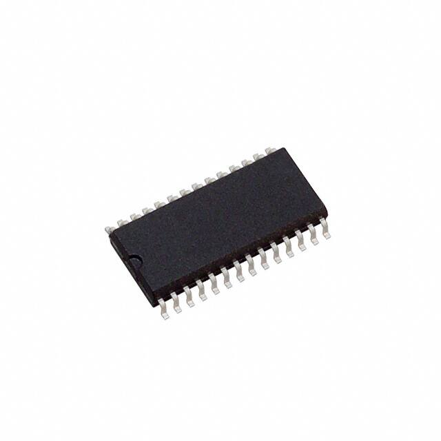


 工商网监
湘ICP备2023018690号
工商网监
湘ICP备2023018690号
