Order
Now
Product
Folder
Support &
Community
Tools &
Software
Technical
Documents
TMP116, TMP116N
SBOS740A – MAY 2017 – REVISED MAY 2019
TMP116 High-Accuracy, Low-Power, Digital Temperature Sensor
With SMBus- and I2C-Compatible Interface
1 Features
3 Description
•
The TMP116 family (TMP116, TMP116N) consist of
low-power, high-precision temperature sensors with
integrated EEPROM memory. The TMP116 provides
a 16-bit temperature result with a resolution of
0.0078°C and an accuracy of up to ±0.2°C with no
calibration. The TMP116 is compatible with the I2Cand SMBus interface, has programmable alert
functionality, and supports up to four devices on a
single bus.
1
•
•
•
•
•
•
•
•
•
TMP116 accuracy without calibration:
– ±0.2°C (maximum) from –10°C to +85°C
– ±0.25°C (maximum) from –40°C to +105°C
– ±0.3°C (maximum) from +105°C to +125°C
TMP116N accuracy, no calibration needed:
– ±0.3°C (maximum) from –25°C to +85°C
– ±0.4°C (maximum) from –40°C to +125°C
Low Quiescent Current:
– 3.5-μA, 1-Hz conversion cycle
– 250-nA shutdown current
Supply range: 1.9 V to 5.5 V
Resolution: 16 bits at 0.0078°C (1 LSB)
Programmable temperature alert limits
Selectable averaging
General-purpose EEPROM: 64 bits
NIST traceability
SMBus™, I2C interface compatibility
2 Applications
•
•
•
•
•
•
•
•
Medical grade: meets ASTM and ISO spec
Environmental monitoring and thermostats
Wearables
Asset tracking and cold chain
Gas meters and heat meters
Test and measurement
RTDs replacement: PT100, PT500, PT1000
Cold-junction compensation of thermocouples
SPACER
Simplified Schematic
The TMP116 consumes minimal current that, in
addition to providing power savings, minimizes selfheating and improves measurement accuracy. The
TMP116 operates from 1.9 V to 5.5 V and typically
consumes 3.5 µA.
Across the device operating temperature range of
–55°C to +125°C, the TMP116 exceeds the accuracy
of a class A RTD, while consuming less than one fifth
of the typical excitation current for a PT100 RTD. The
TMP116 is easier to use than RTDs, eliminating the
need for calibration, external circuitry, matched
traces, and Kelvin connections.
The TMP116 units are 100% tested on a production
setup that is NIST traceable and verified with
equipment that is calibrated to ISO/IEC 17025
accredited standards.
Device Information(1)
PART NUMBER
PACKAGE
TMP116
WSON (6)
(1) For all available packages, see the package option addendum
at the end of the data sheet.
Temperature Accuracy
1.9 V to 5.5 V
Supply Voltage
0.5
Average
116N Max Limit
0.4
0.3
Temperature Error (°C)
5k
Pullup
Resistors
TMP116
Two-Wire
Host Controller
1
2
3
SCL
SDA
GND
V+
ALERT
6
5
4
ADD0
0.1-µF
Supply Bypass
Capacitor
Avg ±3σ
116 Max Limit
0.2
0.1
0
-0.1
-0.2
116 Min Limit
-0.3
116N Min Limit
-0.4
-0.5
-55 -40
Copyright © 2017, Texas Instruments Incorporated
BODY SIZE (NOM)
2.00 mm × 2.00 mm
-20
0
40
60
80
20
Temperature (°C)
100
125
150
1
An IMPORTANT NOTICE at the end of this data sheet addresses availability, warranty, changes, use in safety-critical applications,
intellectual property matters and other important disclaimers. PRODUCTION DATA.
�TMP116, TMP116N
SBOS740A – MAY 2017 – REVISED MAY 2019
www.ti.com
Table of Contents
1
2
3
4
5
6
7
Features ..................................................................
Applications ...........................................................
Description .............................................................
Revision History.....................................................
Pin Configuration and Functions .........................
Specifications.........................................................
1
1
1
2
3
4
6.1
6.2
6.3
6.4
6.5
6.6
6.7
4
4
4
4
5
6
7
Absolute Maximum Ratings ......................................
ESD Ratings..............................................................
Recommended Operating Conditions.......................
Thermal Information ..................................................
Electrical Characteristics...........................................
Two-Wire Interface Timing........................................
Typical Characteristics ..............................................
Detailed Description ............................................ 10
7.1 Overview ................................................................. 10
7.2 Functional Block Diagrams ..................................... 10
7.3 Feature Description................................................. 10
7.4 Device Functional Modes........................................ 12
7.5 Programming........................................................... 17
7.6 Registers Map ......................................................... 24
8
Application and Implementation ........................ 32
8.1 Application Information............................................ 32
9 Power Supply Recommendations...................... 36
10 Layout................................................................... 36
10.1 Layout Guidelines ................................................. 36
10.2 Layout Example .................................................... 38
11 Device and Documentation Support ................. 39
11.1
11.2
11.3
11.4
11.5
11.6
Documentation Support .......................................
Receiving Notification of Documentation Updates
Community Resources..........................................
Trademarks ...........................................................
Electrostatic Discharge Caution ............................
Glossary ................................................................
39
39
39
39
39
39
12 Mechanical, Packaging, and Orderable
Information ........................................................... 39
4 Revision History
Changes from Original (May 2017) to Revision A
Page
•
Added Selectable Averaging feature ..................................................................................................................................... 1
•
Added thermal mass parameter to the Thermal Information table ........................................................................................ 4
•
Added tablenote to the temperature cycling and hysteresis parameter ................................................................................. 5
•
Added TI recommendation to not solder the thermal pad to the PCB in the Layout Guidelines section ............................. 36
2
Submit Documentation Feedback
Copyright © 2017–2019, Texas Instruments Incorporated
Product Folder Links: TMP116
�TMP116, TMP116N
www.ti.com
SBOS740A – MAY 2017 – REVISED MAY 2019
5 Pin Configuration and Functions
DRV Package
6-Pin WSON
Top View
SCL
1
6
SDA
GND
2
5
V+
ALERT
3
4
ADD0
Thermal
Pad
Pin Functions
PIN
NO.
NAME
I/O
DESCRIPTION
1
SCL
I
2
GND
—
Serial clock
Ground
3
ALERT
O
Overtemperature alert or data-ready signal. Open-drain output; requires a pullup resistor if used.
4
ADD0
I
Address select. Connect to GND, V+, SDA, or SCL.
5
V+
I
Supply voltage: 1.9 V to 5.5 V
6
SDA
I/O Serial data input and open-drain output; requires a pullup resistor.
Submit Documentation Feedback
Copyright © 2017–2019, Texas Instruments Incorporated
Product Folder Links: TMP116
3
�TMP116, TMP116N
SBOS740A – MAY 2017 – REVISED MAY 2019
www.ti.com
6 Specifications
6.1 Absolute Maximum Ratings
MIN
MAX
UNIT
Supply voltage, V+
–0.3
6
V
Voltage at SCL, SDA, ALERT, and ADD0
–0.3
6
V
Operating junction temperature, TJ
–55
150
°C
Storage temperature, Tstg
–65
150
°C
6.2 ESD Ratings
VALUE
V(ESD)
(1)
(2)
Electrostatic discharge
Human-body model (HBM), per ANSI/ESDA/JEDEC JS-001 (1)
±2000
Charged-device model (CDM), per JEDEC specification JESD22-C101 (2)
±1000
UNIT
V
JEDEC document JEP155 states that 500-V HBM allows safe manufacturing with a standard ESD control process.
JEDEC document JEP157 states that 250-V CDM allows safe manufacturing with a standard ESD control process.
6.3 Recommended Operating Conditions
MIN
NOM
MAX
V+
Supply voltage
1.9
3.3
5.5
UNIT
V
TA
Operating free-air temperature
–55
150
°C
6.4 Thermal Information
TMP116
THERMAL METRIC
(1)
DRV (WSON)
UNIT
6 PINS
RθJA
Junction-to-ambient thermal resistance
68.7
°C/W
RθJC(top)
Junction-to-case (top) thermal resistance
70.3
°C/W
RθJC(bot)
Junction-to-case (bottom) thermal resistance
9.5
°C/W
RθJB
Junction-to-board thermal resistance
38.3
°C/W
ψJT
Junction-to-top characterization parameter
1.7
°C/W
ψJB
Junction-to-board characterization parameter
38.6
°C/W
MT
Thermal Mass
5.1
mJ/°C
(1)
4
For more information about traditional and new thermal metrics, see the Semiconductor and IC Package Thermal Metrics application
report.
Submit Documentation Feedback
Copyright © 2017–2019, Texas Instruments Incorporated
Product Folder Links: TMP116
�TMP116, TMP116N
www.ti.com
SBOS740A – MAY 2017 – REVISED MAY 2019
6.5 Electrical Characteristics
minimum and maximum specifications are over –55°C to +125°C and V+ = 1.9 V to 5.5 V (unless otherwise noted); typical
specifications are at TA = 25°C and V+ = 3.3 V
PARAMETER
TEST CONDITIONS
MIN
TYP
MAX
UNIT
TEMPERATURE-TO-DIGITAL CONVERTER
–10°C to +85°C, V+ = 3.3 V
TMP116
Temperature
accuracy (1)
TMP116N
DC power-supply sensitivity
–0.2
±0.1
0.2
–40°C to +105°C, V+ = 3.0 V to 3.6 V
–0.25
±0.2
0.25
+105°C to +125°C, V+ = 3.0 V to 3.6 V
–0.3
±0.25
0.3
–40°C to +125°C, V+ = 1.9 V to 5.5 V (2)
–0.4
±0.3
0.4
–25°C to +85°C, V+ = 3.3 V
–0.3
±0.2
0.3
–40°C to +125°C, V+ = 3.0 V to 3.6 V
–0.4
±0.3
0.4
–40°C to +125°C V+ = 1.9 V to 5.5 V (2)
–0.5
±0.4
0.5
One-shot mode, 8 averages, TA = 25°C
0
20
55
Temperature resolution (LSB)
Repeatability (3)
V+ = 3.3 V, 8 averages, 1-Hz sampling
Long-term stability and drift
300 hours at 150°C (4)
m°C/V
7.8125
m°C
±1
LSB
±0.02
Temperature cycling and
hysteresis (1) (5)
°C
°C
±1
LSB
3
pF
DIGITAL INPUT/OUTPUT
Input capacitance
VIH
Input logic high level
VIL
Input logic low level
IIN
Input current
VOLS
SDA output logic low level
VOLA
ALERT output logic low level
0.7 (V+)
V
0.3 (V+)
V
–0.2
0.2
µA
IOL = –3 mA
0
0.4
V
IOL = –3 mA
0
0.4
V
POWER SUPPLY
IQ
Quiescent current
ISB
Standby current
ISD
(6)
Shutdown current
Active conversion, serial bus inactive
135
220
1-Hz conversion cycle, averaging mode off,
serial bus inactive, 25°C
3.5
4.5
1-Hz conversion cycle, 8 averages mode,
serial bus inactive, 25°C
16
22
1-Hz conversion cycle, averaging mode off,
serial bus active, SCL frequency = 400 kHz
21
Serial bus inactive, SCL and SDA = V+, 25°C
1.25
2.1
Serial bus inactive, SCL and SDA = V+, 25°C
0.25
0.5
Serial bus inactive, SCL and SDA = V+, 125°C
8.5
Serial bus active, SCL frequency = 400 kHz
µA
µA
µA
17
IEE
EEPROM write quiescent current
ADC conversion off; serial bus inactive
240
µA
VPOR
Power-on-reset threshold voltage
V+ rising
1.6
V
Brownout detect
V+ falling
1.1
V
Reset time
Time required by device to reset
1.5
ms
Active conversion time
1 conversion
(1)
(2)
(3)
(4)
(5)
(6)
13.5
15.5
17
ms
8 averages, 1-Hz conversion cycle. Measurements are taken in oil bath.
±0.75°C maximum error between –55°C to –40°C.
Repeatability is the ability to reproduce a reading when the measured temperature is applied consecutively, under the same conditions.
Long-term stability is determined using accelerated operational life testing at a junction temperature of 150°C.
Hysteresis is defined as the ability to reproduce a temperature reading as the temperature varies from room → hot → room → cold →
room. The temperatures used for this test are –40°C, 25°C, and 125°C.
Quiescent current between conversions.
Submit Documentation Feedback
Copyright © 2017–2019, Texas Instruments Incorporated
Product Folder Links: TMP116
5
�TMP116, TMP116N
SBOS740A – MAY 2017 – REVISED MAY 2019
www.ti.com
Electrical Characteristics (continued)
minimum and maximum specifications are over –55°C to +125°C and V+ = 1.9 V to 5.5 V (unless otherwise noted); typical
specifications are at TA = 25°C and V+ = 3.3 V
PARAMETER
TEST CONDITIONS
MIN
TYP
MAX
UNIT
1,000
50,000
Times
10
100
Years
EEPROM
Programming time
7
Number of writes
Data retention time
ms
6.6 Two-Wire Interface Timing
minimum and maximum specifications are over –55°C to 125°C and V+ = 1.9 V to 5.5 V (unless otherwise noted); typical
specifications are at TA = 25°C and V+ = 3.3 V; values are based on statistical analysis of samples tested during initial
release
MIN
MAX
UNIT
1
400
kHz
fSCL
SCL operating frequency
tBUF
Bus free time between STOP and START conditions
1300
ns
tHD;STA
Hold time after repeated START condition.
After this period, the first clock is generated.
600
ns
tSU;STA
Repeated START condition setup time
600
ns
tSU;STO
STOP condition setup time
600
ns
tHD;DAT
Data hold time
0
ns
(1)
tVD;DAT
Data valid time
tSU;DAT
Data setup time
0.9
tLOW
SCL clock low period
tHIGH
SCL clock high period
tF – SDA
Data fall time
tF, tR – SCL
Clock fall and rise time
tR
Rise time for SCL ≤ 100 kHz
ns
1300
ns
600
20 × (V+ / 5.5)
Serial bus timeout (SDA bus released if there is no clock)
(1)
µs
100
20
ns
300
ns
300
ns
1000
ns
40
ms
tVD;DATA = time for data signal from SCL low to SDA output (high to low, depending on which is worse).
tLOW
tR
VIH
SCL
tHIGH
VIL
tHD;STA
tBUF
SDA
tF
tHD;DAT
tVD;DAT
tSU;STA
tSU;DAT
tSU;STO
VIH
VIL
P
S
S
P
Figure 1. Two-Wire Timing Diagram
6
Submit Documentation Feedback
Copyright © 2017–2019, Texas Instruments Incorporated
Product Folder Links: TMP116
�TMP116, TMP116N
www.ti.com
SBOS740A – MAY 2017 – REVISED MAY 2019
6.7 Typical Characteristics
at TA = 25°C, V+ = 3.3 V, and measurement taken in oil bath (unless otherwise noted)
0.5
Average
116N Max Limit
0.4
1 Shot, No Conv Cycles
8 Averages, Conv Cycle = 1 s
1 Conversion, Conv Cycle = 500 ms
60
Temperature Error (mqC)
50
0.3
Temperature Error (°C)
70
Avg ±3σ
116 Max Limit
0.2
0.1
0
-0.1
-0.2
116 Min Limit
-0.3
40
30
20
10
0
-10
-20
116N Min Limit
-0.4
-30
-40
-0.5
-55 -40
-20
0
40
60
80
20
Temperature (°C)
125
100
1
150
1.5
2
2.5
3
3.5
4
4.5
Supply Voltage (V)
5
5.5
6
1-Hz conversion cycle, 8 averages mode
Figure 3. Temperature Error vs Supply Voltage
80
100
90
80
70
60
50
40
30
20
10
0
-10
-20
-30
-40
-50
-60
1.5
V = +1.9 V, St. Dev = 0.91
V = +3.3 V, St. Dev = 1.01
V = +5 V, St. Dev = 0.96
70
60
Population (%)
Temperature Error (mqC)
Figure 2. Temperature Error vs Temperature
50
40
30
20
10
0
2
2.5
3
3.5
4
Supply Voltage (V)
4.5
5
-4
5.5
-3
-2
-1
0
1
2
Data Distribution (LSB)
3
4
Continuous conversion, no conversion cycle normalized to 3.3V
Figure 4. Temperature Error vs Supply Voltage in still air
Figure 5. Data Reading Distribution Over Supply Voltage
(No Averaging)
80
80
-40°C, St. Dev = 1.12
25°C, St. Dev = 1.01
125°C, St. Dev = 1.05
70
60
Population (%)
60
Population (%)
Avrg 8, St. Dev = 0.51
Avrg 32, St. Dev = 0.56
Avrg 64, St. Dev = 0.61
70
50
40
30
50
40
30
20
20
10
10
0
0
-4
-3
-2
-1
0
1
2
Data Distribution (LSB)
3
4
Figure 6. Data Reading Distribution Over Temperature
(No Averaging)
-4
-3
-2
-1
0
1
2
Data Distribution (LSB)
3
4
Figure 7. Data Reading Distribution Over Averaging Number
Submit Documentation Feedback
Copyright © 2017–2019, Texas Instruments Incorporated
Product Folder Links: TMP116
7
�TMP116, TMP116N
SBOS740A – MAY 2017 – REVISED MAY 2019
www.ti.com
Typical Characteristics (continued)
at TA = 25°C, V+ = 3.3 V, and measurement taken in oil bath (unless otherwise noted)
10
10
5.5 V
9
3.3 V
8
1.9 V
7
Current (µA)
Current (µA)
3.3 V
8
1.9 V
7
5.5 V
9
6
5
4
6
5
4
3
3
2
2
1
1
0
0
–50
0
–25
25
50
75
100
–50
125
25
50
Temperature (°C)
Serial bus inactive
Serial bus inactive
75
100
125
Figure 9. Quiescent Current in Standby Mode
Figure 8. Quiescent Current in Shutdown Mode
110
200
150qC
125qC
100qC
25qC
0qC
-50qC
160
5.5 V
3.3 V
1.9 V
100
90
80
Current (PA)
180
Current (PA)
0
–25
Temperature (°C)
140
120
100
70
60
50
40
30
20
80
10
60
1.3
1.8
2.3
2.8
3.3 3.8 4.3 4.8
Supply Voltage (V)
5.3
5.8
6.3
0
0.1
6.8
Continuous conversion mode, serial bus inactive
Active Conversion Time Change
Percentage (%)
Power (mWt)
0.9
1
1.9 V
3.3 V
5.5 V
4
0.6
0.5
0.4
0.3
0.2
3
2
1
0
-1
-2
-3
-4
0.1
2
2.5
3
3.5
4
4.5
Supply Voltage (V)
5
5.5
6
-5
-55
Serial bus inactive
-25
5
35
65
Temperature (°C)
95
125
150
Normalized to 25°C and V+ = 3.3 V
Figure 12. Power Consumption During Active Conversion
8
0.8
5
+125qC
+25qC
-50qC
0.7
0
1.5
0.4
0.5
0.6
0.7
Bus Frequency (MHz)
Figure 11. Quiescent Current in Shutdown Mode
1
0.8
0.3
SCL, SDA, ADD0 pins are constantly clocked
Figure 10. Quiescent Current During Active Conversion
0.9
0.2
Figure 13. Active Conversion Time vs Temperature
Submit Documentation Feedback
Copyright © 2017–2019, Texas Instruments Incorporated
Product Folder Links: TMP116
�TMP116, TMP116N
www.ti.com
SBOS740A – MAY 2017 – REVISED MAY 2019
Typical Characteristics (continued)
at TA = 25°C, V+ = 3.3 V, and measurement taken in oil bath (unless otherwise noted)
1
1.9 V
3.3 V
5.5 V
8
6
0.8
4
0.7
2
0.6
0
-2
0.5
0.4
-4
0.3
-6
0.2
-8
0.1
-10
-50
-30
-10
10
30
50
70
90
Temperature (qC)
110
130
1.9 V
2V
3.3 V
5.5 V
0.9
Vout (V)
Standby Time Change Percentage (%)
10
0
150
0
2
4
6
8 10 12 14 16 18 20 22 24 26 28 30
Sink Current (mA)
Normalized to 25°C and V+ = 3.3 V
Current (PA)
Figure 14. Standby Time vs Temperature
Figure 15. ALERT Pin Output Voltage vs Pin Sink Current
650
600
550
500
450
400
350
300
250
200
150
100
50
0
5.5 V
4.4 V
3.3 V
2V
0
10
20
30
40
50
60
Vin / V+ (%)
70
80
90
100
Input voltage of SCL, SDA, or ADD0 pin
Figure 16. Supply Current vs Input Cell Input Voltage
Submit Documentation Feedback
Copyright © 2017–2019, Texas Instruments Incorporated
Product Folder Links: TMP116
9
�TMP116, TMP116N
SBOS740A – MAY 2017 – REVISED MAY 2019
www.ti.com
7 Detailed Description
7.1 Overview
The TMP116 is a digital output temperature sensor that is optimal for thermal-management and thermalprotection applications. The TMP116 is two-wire, SMBus, and I2C interface-compatible. The device is specified
over an operating temperature range of –55°C to +125°C. Figure 17 shows a block diagram of the TMP116.
Figure 18 shows the ESD protection circuitry contained in the TMP116.
7.2 Functional Block Diagrams
Temperature
GND
ALERT
1
2
3
Diode
Temp.
Sensor
Control
Logic
6
'6
A/D
Converter
Serial
Interface
5
Config.
and Temp.
Register
4
OSC
EEPROM
SCL
SDA
V+
ADD0
Figure 17. Internal Block Diagram
SCL
SDA
V+
GND
Core
ALERT
ADD0
Figure 18. Equivalent Internal ESD Circuitry
7.3 Feature Description
7.3.1 Power Up
After the supply voltage reaches within the operating range, the device requires 1.5 ms to power up before
conversions begin. The device can be programmed to startup in shutdown mode as well; see the EEPROM
Programming section. The temperature register stores –256°C before the first conversion end.
10
Submit Documentation Feedback
Copyright © 2017–2019, Texas Instruments Incorporated
Product Folder Links: TMP116
�TMP116, TMP116N
www.ti.com
SBOS740A – MAY 2017 – REVISED MAY 2019
Feature Description (continued)
7.3.2 Temperature Result and Limits
At the end of every conversion or averaging cycle, the device updates the temperature register with the
conversion result. The data reading in the result register is in two's complement format, has a data width of 16
bits, and a resolution of 7.8125 m°C. Table 1 shows multiple examples of possible binary data that can be read
from the temperature result register and the corresponding hexadecimal and decimal equivalents.
The TMP116 also has alert status flags and alert pin functionality that use the temperature limits stored in the low
limit register and high limit register. The alert registers use the same data format as the temperature register.
Table 1. 16-Bit Temperature Data Format
TEMPERATURE
(°C)
TEMPERATURE REGISTER VALUE
(0.0078125°C RESOLUTION)
BINARY
HEX
–256
1000 0000 0000 0000
8000
–25
1111 0011 1000 0000
F380
–0.1250
1111 1111 1111 0000
FFF0
–0.0078125
1111 1111 1111 1111
FFFF
0
0000 0000 0000 0000
0000
0.0078125
0000 0000 0000 0001
0001
0.1250
0000 0000 0001 0000
0010
1
0000 0000 1000 0000
0080
25
0000 1100 1000 0000
0C80
100
0011 0010 0000 0000
3200
255.9921
0111 1111 1111 1111
7FFF
Submit Documentation Feedback
Copyright © 2017–2019, Texas Instruments Incorporated
Product Folder Links: TMP116
11
�TMP116, TMP116N
SBOS740A – MAY 2017 – REVISED MAY 2019
www.ti.com
7.4 Device Functional Modes
7.4.1 Temperature Conversions
The TMP116 can be configured to operate in various conversion modes by using the MOD[1:0] bits. These
modes provide flexibility to operate the device in the most power efficient way required for the intended
application.
7.4.1.1 Conversion Cycle
When the device is operating in continuous conversion mode (see the Continuous Conversion Mode (CC)
section), every conversion cycle consists of an active conversion period followed by a standby period. During
active conversion the device typically consumes 135 µA, and during the low-power standby period the device
typically consumes 1.25 µA, as indicated in Table 1. Figure 19 shows a current consumption profile of a
conversion cycle. The duration of the active conversion period and standby period can be configured using the
CONV[2:0] and AVG[1:0] bits in the configuration register, thereby allowing the average current consumption of
the device to be optimized based on the application requirements. Changing the conversion cycle period also
affects the temperature result update rate because the temperature result register is updated at the end of every
conversion or averaging cycle.
1 Conversion Cycle
Active Conversion
Standby
15.5 ms
15.5 ms
Start-Up
Start of
Conversion
Figure 19. Conversion Cycle Timing Diagram
7.4.1.2 Averaging
Noise in the conversion result can be reduced by configuring the device to report the average of multiple
temperature conversions using the AVG[1:0] bits. When the TMP116 is configured to perform averaging, the
device executes the configured number of conversions while accumulating the results and reports the average of
all conversion results at the end of the process. As illustrated in the noise histograms of Figure 6 and Figure 7,
the temperature result output has a repeatability of approximately ±3 LSBs when there is no averaging and ±1
LSB when the device is configured to perform eight averages or higher. As illustrated in Figure 20, this
improvement in noise performance is achieved with the tradeoff of an increase in the active conversion time in a
conversion cycle, thereby increasing the average active current consumption. For example, a single active
conversion typically takes 15.5 ms so if the device is configured to report an average of eight conversions then
the active conversion time is 124 ms (15.5 ms × 8). Use Equation 1 to factor in this increase in active conversion
time to accurately calculate the average current consumption of the device. The average current consumption of
the device can be decreased by increasing the amount of time the device spends in standby period as compared
to active conversion. Under the factory EEPROM settings, the device is configured to report an average of eight
conversions with a conversion cycle time of 1 second.
12
Submit Documentation Feedback
Copyright © 2017–2019, Texas Instruments Incorporated
Product Folder Links: TMP116
�TMP116, TMP116N
www.ti.com
SBOS740A – MAY 2017 – REVISED MAY 2019
Device Functional Modes (continued)
1 Second
124 ms
8 Conv
8 Averages, 1-Hz CC
Standby
15.5 ms
I2C Temperature or
Configuration Register Read
Data_Ready Flag
Figure 20. Averaging Timing Diagram
Use Equation 1 to calculate the average current consumption of the device in continuous mode.
(Active Current Consumption u Active Conversion Time) + (Standby Current Consumption u Standby Time)
Conversion Cycle Time
(1)
7.4.1.3 Continuous Conversion Mode (CC)
When the MOD[1:0] bits are set to 00, the TMP116 operates in continuous conversion mode. In this mode, the
device continuously performs temperature conversions as illustrated in Figure 19 and updates the temperature
result register at the end of every conversion or averaging cycle. As described in the Conversion Cycle section,
every conversion cycle consists of an active conversion period followed by a standby period whose duration can
be configured using the CONV and AVG bits in the configuration register. The configuration is based on the
temperature accuracy, power consumption, and temperature update rate. At the end of a conversion, the
Data_Ready flag in the configuration register is set. The Data_Ready flag is cleared by reading the configuration
register or the temperature result register. The state of the Data_Ready flag can also be monitored on the
ALERT pin by setting the DR/nAlert_EN bit in the configuration register.
7.4.1.4 Shutdown Mode (SD)
When 01 is written to the MOD bits in the configuration register, the device instantly aborts the currently running
conversion and enters a low-power shutdown mode. In this mode, the device powers down all active circuitry. In
SD mode, the device typically consumes only 250 nA, which makes the TMP116 suitable for low-power
consumption applications, such as battery-operated systems.
Submit Documentation Feedback
Copyright © 2017–2019, Texas Instruments Incorporated
Product Folder Links: TMP116
13
�TMP116, TMP116N
SBOS740A – MAY 2017 – REVISED MAY 2019
www.ti.com
Device Functional Modes (continued)
7.4.1.5 One-Shot Mode (OS)
When in shutdown mode, a single conversion can be performed by writing 11 to MOD bits in the configuration
register, referred to as a one-shot conversion. After completing a one-shot conversion, the device returns to the
low-power shutdown mode. A one-shot conversion cycle only consists of active conversion time and no standby
period unlike CC mode. Thus, the duration of a one-shot conversion is only affected by the settings in the AVG
bits. Figure 21 shows a timing diagram for this mode with an AVG setting of 00 and Figure 22 shows a timing
diagram for this mode with an AVG setting of 01. At the end of a one-shot conversion, the Data_Ready flag in
the configuration register is set. The Data_Ready flag is cleared by read of the configuration register or
temperature result register. The state of the Data_Ready flag can also be monitored on the ALERT pin by setting
the DR/nAlert_EN bit in the configuration register.
Shutdown
15.5 ms
(One-Shot Conversion)
Figure 21. One-Shot Timing Diagram With No Averaging
Shutdown
125 ms
(One-Shot Conversion)
Figure 22. One-Shot Timing Diagram With 8 Averages
7.4.2 Therm and Alert Modes
The TMP116 can be used to detect if the temperature has crossed a certain temperature limit or if the device is
within a certain temperature range by using the therm or alert functions built into the device. At the end of every
conversion, the TMP116 compares the converted temperature result to the values stored in the low limit register
and high limit register and sets or clears the corresponding status flags in the configuration register, as described
in this section.
14
Submit Documentation Feedback
Copyright © 2017–2019, Texas Instruments Incorporated
Product Folder Links: TMP116
�TMP116, TMP116N
www.ti.com
SBOS740A – MAY 2017 – REVISED MAY 2019
Device Functional Modes (continued)
7.4.2.1 Alert Mode
When the T/nA bit in the configuration register is set to 0, the device is in alert mode. In this mode, the device
compares the conversion result at the end of every conversion with the values in the low limit register and high
limit register. If the temperature result exceeds the value in the high limit register, the HIGH_Alert status flag in
the configuration register is set. On the other hand, if the temperature result is lower than the value in the low
limit register, the LOW_Alert status flag in the configuration register is set. As shown in Figure 23, in alert mode
the status flags can be cleared by performing an I2C read of the configuration register.
Configuring the device in alert mode also affects the behaviour of the ALERT pin. In this mode, the device
asserts the ALERT pin when either the HIGH_Alert or the LOW_Alert status flag is set as shown in Figure 23.
The ALERT pin can be deasserted by either performing an I2C read of the configuration register (which also
clears the status flags) or by performing an SMBus alert response command (see the SMBus Alert Function
section). The polarity of the ALERT pin can be changed by using the POL bit setting in the configuration register.
This mode effectively makes the device behave like a window limit detector and can be used in applications
where detecting if the temperature goes outside of the specified range is needed.
High temperature limit
Temperature
Low temperature limit
Temperature conversions
HIGH_Alert Status Flag
LOW_Alert Status Flag
ALERT pin (POL = 0)
Configuration Register I2C Read
SMBus Alert Response Command
Figure 23. Alert Mode Timing Diagram
Submit Documentation Feedback
Copyright © 2017–2019, Texas Instruments Incorporated
Product Folder Links: TMP116
15
�TMP116, TMP116N
SBOS740A – MAY 2017 – REVISED MAY 2019
www.ti.com
Device Functional Modes (continued)
7.4.2.2 Therm Mode
When the T/nA bit in the configuration register is set to 1 the device is in therm mode. In this mode, the device
compares the conversion result at the end of every conversion with the values in the low limit register and high
limit register and sets the HIGH_Alert status flag in the configuration register if the temperature exceeds the
value in the high limit register. When set, the device clears the HIGH_Alert status flag if the conversion result
goes below the value in the low limit register. Thus, the difference between the high and low limits effectively acts
like a hysteresis. In this mode, the LOW_Alert status flag is disabled and always reads 0. Unlike the alert mode,
I2C reads of the configuration register do not affect the status bits. The HIGH_Alert status flag is only set or
cleared at the end of conversions based on the value of the temperature result compared to the high and low
limits.
As in alert mode, configuring the device in therm mode also affects the behaviour of the ALERT pin. In this
mode, the device asserts the ALERT pin if the HIGH_Alert status flag is set and deasserts the ALERT pin when
the HIGH_Alert status flag is cleared. In therm mode, the ALERT pin cannot be cleared by performing an I2C
read of the configuration register or by performing an SMBus alert response command. As in alert mode, the
polarity of the active state of the ALERT pin can be changed by using the POL bit setting in the configuration
register.
Thus, this mode effectively makes the device behave like a high-limit threshold detector and can be used in
applications where detecting if the temperature has gone above a desired threshold is needed. Figure 24 shows
a timing diagram of this mode.
High temperature limit
Temperature
Low temperature limit
Temperature conversions
HIGH_Alert Status Flag
ALERT pin (POL = 0)
I2C Read
Figure 24. Therm Mode Timing Diagram
16
Submit Documentation Feedback
Copyright © 2017–2019, Texas Instruments Incorporated
Product Folder Links: TMP116
�TMP116, TMP116N
www.ti.com
SBOS740A – MAY 2017 – REVISED MAY 2019
7.5 Programming
7.5.1 EEPROM Programming
7.5.1.1 EEPROM Overview
The device consists of a user-programmable EEPROM that can be used for two purposes:
• Storing the reset values of configuration register and alert registers
• Four 16-bit locations for general-purpose use; see the EEPROM[4:1] registers
On reset, the device goes through a reset sequence that loads the values programmed in the EEPROM into the
respective register map locations. This process takes approximately 1.5 ms. When the reset sequence is
completed the device starts operating in accordance to the configuration parameters that are loaded from the
EEPROM. Any I2C writes performed during this initial period to the registers are ignored. I2C read transactions
can still be performed with the device during the reset period. While the reset sequence is being executed, the
EEPROM_Busy status flag in the EEPROM unlock register is cleared.
During production, the EEPROM in the TMP116 is programmed with reset values as shown in Table 3. The
Programming the EEPROM section describes how to change these values. Additionally, during production a
unique ID is programmed in the general-purpose EEPROM locations. This unique ID is used to support NIST
traceability. The TMP116 units are 100% tested on a production setup that is NIST traceable and verified with
equipment that is calibrated to ISO/IEC 17025 accredited standards. Only reprogram the general-purpose
EEPROM[4:1] locations if NIST traceability is not desired.
7.5.1.2 Programming the EEPROM
To prevent accidental programming, the EEPROM is locked by default. When locked, any I2C writes to the
register map locations are performed only on the volatile registers and not on the EEPROM.
Figure 25 illustrates a flow chart describing the EEPROM programming sequence. To program the EEPROM,
first unlock the EEPROM by setting the EUN bit in the EEPROM unlock register. After the EEPROM is unlocked,
any subsequent I2C writes to the register map locations program a corresponding non-volatile memory location in
the EEPROM. Programming a single location typically takes 7 ms to complete and consumes 230 µA. Do not
perform any I2C writes until programming is completed. During programming, the EEPROM_busy flag is set.
Read this flag to monitor if the programming is complete. After programming the desired data, issue a generalcall reset command to trigger a software reset. The programmed data from the EEPROM are then loaded to the
corresponding register map locations as part of the reset sequence. This command also clears the EUN bit and
automatically locks the EEPROM to prevent any further accidental programming. The application must avoid
temperature conversions when the EEPROM is unlocked.
Submit Documentation Feedback
Copyright © 2017–2019, Texas Instruments Incorporated
Product Folder Links: TMP116
17
�TMP116, TMP116N
SBOS740A – MAY 2017 – REVISED MAY 2019
www.ti.com
Programming (continued)
Start
Set Bit 15 of the EEPROM
Unlock Register to 1 to Unlock
Write Desired Data to the Register
Wait 7 ms
Programming Process
EEPROM_Busy = 1
(Still Programming)
Read Back EEPROM_Busy
From EEPROM Unlock
Register
EEPROM_Busy = 0
(Programming Complete)
Program Another Location?
Yes
No
General-Call Reset
Read Programed Registers to Verify
End
Figure 25. EEPROM Programming Sequence
18
Submit Documentation Feedback
Copyright © 2017–2019, Texas Instruments Incorporated
Product Folder Links: TMP116
�TMP116, TMP116N
www.ti.com
SBOS740A – MAY 2017 – REVISED MAY 2019
Programming (continued)
7.5.2 Pointer Register
Figure 26 shows the internal register structure of the TMP116. The 8-bit pointer register of the device is used to
address a given data register. The power-up reset value is 00. By default, the TMP116 reads the temperature on
power-up.
Pointer
Register
Temperature
Register
SCL
Configuration
Register
TLOW
Register
I/O
Control
Interface
SDA
THIGH
Register
EEPROM1 to 4
Figure 26. Internal Registers Structures
7.5.3 I2C and SMBus Interface
7.5.3.1 Serial Interface
The TMP116 operates as a slave device on the two-wire, SMBus and I2C interface-compatible bus. Connections
to the bus are made through the open-drain I/O lines SDA and SCL pins. The SDA and SCL pins feature
integrated spike-suppression filters and Schmitt triggers to minimize the effects of input spikes and bus noise.
The device supports the transmission protocol for fast (1 kHz to 400 kHz) mode. Register bytes are sent with the
most significant byte first, followed by the least significant byte.
7.5.3.1.1 Bus Overview
The device that initiates the transfer is called a master, and the devices controlled by the master are slaves. The
bus is controlled by a master device that generates the serial clock (SCL), controls the bus access, and
generates the START and STOP conditions.
To address a specific device, a START condition is initiated, indicated by pulling the data line (SDA) from a highto low-logic level when the SCL pin is high. All slaves on the bus shift in the slave address byte on the rising
edge of the clock, with the last bit indicating whether a read or write operation is intended. During the ninth clock
pulse, the slave being addressed responds to the master by generating an acknowledge and pulling the SDA pin
low.
A data transfer is then initiated and sent over eight clock pulses followed by an acknowledge bit. During the data
transfer, the SDA pin must remain stable when the SCL pin is high because any change in the SDA pin when the
SCL pin is high is interpreted as a START or STOP signal.
When all data are transferred, the master generates a repeated START or STOP condition. The STOP condition
is indicated by pulling the SDA pin from low to high when the SCL pin is high.
Submit Documentation Feedback
Copyright © 2017–2019, Texas Instruments Incorporated
Product Folder Links: TMP116
19
�TMP116, TMP116N
SBOS740A – MAY 2017 – REVISED MAY 2019
www.ti.com
Programming (continued)
7.5.3.1.2 Serial Bus Address
To communicate with the TMP116, the master must first address slave devices through an address byte. The
address byte consists of seven address bits and a read-write (R/W) bit indicating the intent of executing a read or
write operation.
The TMP116 features an address pin to allow up to four devices to be addressed on a single bus. Table 2
describes the pin connection used to properly address up to four devices. x represents the read-write (R/W) bit.
Table 2. Address Pin and Slave Addresses
DEVICE ADDRESS
ADD0 PIN CONNECTION
1001000x
Ground
1001001x
V+
1001010x
SDA
1001011x
SCL
7.5.3.1.3 Writing and Reading Operation
Accessing a particular register on the TMP116 is accomplished by writing the register address to the pointer
register. The value for the pointer register is the first byte transferred after the slave address byte with the R/W
bit low. Every write operation to the TMP116 requires a value for the pointer register.
When reading from the TMP116, the last value stored in the pointer register by a write operation is used to
determine which register is read by a read operation. To change the register pointer for a read operation, a new
value must be written to the pointer register. This action is accomplished by issuing an address byte with the
R/W bit low, followed by the pointer register byte. No additional data are required. The master can then generate
a START condition and send the slave address byte with the R/W bit high to initiate the read command; see
Figure 28 for details of this sequence. If repeated reads from the same register are desired, continuously sending
the pointer register bytes is not necessary because the TMP116 retains the pointer register value until the value
is changed by the next write operation.
Register bytes are sent with the most significant byte first, followed by the least significant byte.
7.5.3.1.4 Slave Mode Operations
The TMP116 can operate as a slave receiver or slave transmitter. As a slave device, the TMP116 never drives
the SCL line.
7.5.3.1.4.1 Slave Receiver Mode
The first byte transmitted by the master is the slave address with the R/W bit low. The TMP116 then
acknowledges reception of a valid address. The next byte transmitted by the master is the pointer register. The
TMP116 then acknowledges reception of the pointer register byte. The next byte or bytes are written to the
register addressed by the pointer register. The TMP116 acknowledges reception of each data byte. The master
can terminate data transfer by generating a START or STOP condition.
7.5.3.1.4.2 Slave Transmitter Mode
The first byte transmitted by the master is the slave address with the R/W bit high. The slave acknowledges
reception of a valid slave address. The next byte is transmitted by the slave and is the most significant byte of
the register indicated by the pointer register. The master acknowledges reception of the data byte. The next byte
transmitted by the slave is the least significant byte. The master acknowledges reception of the data byte. The
master can terminate data transfer by generating a not-acknowledge on reception of any data byte or by
generating a START or STOP condition.
20
Submit Documentation Feedback
Copyright © 2017–2019, Texas Instruments Incorporated
Product Folder Links: TMP116
�TMP116, TMP116N
www.ti.com
SBOS740A – MAY 2017 – REVISED MAY 2019
7.5.3.1.5 SMBus Alert Function
The TMP116 supports the SMBus alert function. When the ALERT pin is connected to an SMBus alert signal and
a master senses that an alert condition is present, the master can send out an SMBus ALERT command (0001
1001) to the bus. If the ALERT pin is active, the device acknowledges the SMBus ALERT command and
responds by returning the slave address on the SDA line. The eighth bit (LSB) of the slave address byte
indicates if the alert condition is caused by the temperature exceeding T(HIGH) or falling below T(LOW). The LSB is
high if the temperature is greater than T(HIGH), or low if the temperature is less than T(LOW); see Figure 29 for
details of this sequence.
If multiple devices on the bus respond to the SMBus ALERT command, arbitration during the slave address
portion of the SMBus ALERT command determines which device clears the alert status of that device. The
device with the lowest two-wire address wins the arbitration. If the TMP116 wins the arbitration, the TMP116
ALERT pin becomes inactive at the completion of the SMBus ALERT command. If the TMP116 loses the
arbitration, the TMP116 ALERT pin remains active.
7.5.3.1.6 General-Call Reset Function
The TMP116 responds to a two-wire, general-call address (0000 000) if the eighth bit is 0. The device
acknowledges the general-call address and responds to commands in the second byte. If the second byte is
0000 0110, the TMP116 internal registers are reset to power-up values.
7.5.3.1.7 Timeout Function
The TMP116 resets the serial interface if the SCL line is held low by the master or the SDA line is held low by
the TMP116 for 35 ms (typical) between a START and STOP condition. The TMP116 releases the SDA line if
the SCL pin is pulled low and waits for a START condition from the host controller. To avoid activating the
timeout function, maintain a communication speed of at least 1 kHz for the SCL operating frequency.
7.5.3.1.8 Timing Diagrams
The TMP116 is two-wire, SMBus, and I2C interface-compatible. Figure 27 to Figure 30 describe the various
operations on the TMP116. Parameters for Figure 1 are defined in Two-Wire Interface Timing. Bus definitions
are:
Bus Idle: Both SDA and SCL lines remain high.
Start Data Transfer: A change in the state of the SDA line from high to low when the SCL line is high defines a
START condition. Each data transfer is initiated with a START condition.
Stop Data Transfer: A change in the state of the SDA line from low to high when the SCL line is high defines a
STOP condition. Each data transfer is terminated with a repeated START or STOP condition.
Data Transfer: The number of data bytes transferred between a START and a STOP condition is not limited and
is determined by the master device.
Acknowledge: Each receiving device, when addressed, is obliged to generate an acknowledge bit. A device that
acknowledges must pull down the SDA line during the acknowledge clock pulse in such a way that the SDA line
is stable low during the high period of the acknowledge clock pulse. Setup and hold times must be taken into
account. On a master receive, the termination of the data transfer can be signaled by the master generating a
not-acknowledge (1) on the last byte transmitted by the slave.
Submit Documentation Feedback
Copyright © 2017–2019, Texas Instruments Incorporated
Product Folder Links: TMP116
21
�TMP116, TMP116N
SBOS740A – MAY 2017 – REVISED MAY 2019
www.ti.com
1
9
1
9
SCL
¼
1
SDA
0
0
0
1
A1
A0
0
R/W
Start By
Master
0
P3
0
0
P2
P1
P0
ACK By
Device
¼
ACK By
Device
Frame 2 Pointer Register Byte
Frame 1 Two-Wire Slave Address Byte
1
9
1
9
SCL
(Continued)
SDA
(Continued)
D15 D14
D13
D12 D11
D10
D9
D7
D8
D6
D5
D4
D3
D2
D1
D0
ACK By
Device
ACK By
Device
Stop By
Master
Frame 4 Data Byte 2
Frame 3 Data Byte 1
Figure 27. Write Word Command Timing Diagram
1
9
1
9
SCL
¼
SDA
1
0
0
1
0
A1
A0
R/W
Start By
Master
0
0
0
0
P3
P2
P1
P0
ACK By
Device
¼
ACK By
Device
Frame 2 Pointer Register Byte
Frame 1 Two-Wire Slave Address Byte
1
9
1
9
SCL
(Continued)
¼
SDA
(Continued)
1
0
1
0
0
A1
A0
R/W
Start By
Master
D15
D14
D13
D12 D11
ACK By
Device
Frame 3 Two-Wire Slave Address Byte
1
D10
D9
D8
From
Device
¼
ACK By
Master
Frame 4 Data Byte 1 Read Register
9
SCL
(Continued)
SDA
(Continued)
D7
D6
D5
D4
D3
From
Device
D2
D1
D0
NACK By
Master
Stop By
Master
Frame 5 Data Byte 2 Read Register
Figure 28. Read Word Command Timing Diagram
22
Submit Documentation Feedback
Copyright © 2017–2019, Texas Instruments Incorporated
Product Folder Links: TMP116
�TMP116, TMP116N
www.ti.com
SBOS740A – MAY 2017 – REVISED MAY 2019
ALERT
1
9
1
9
SCL
SDA
0
0
0
1
1
0
0
R/W
Start By
Master
1
0
0
1
0
A1
ACK By
Device
(1)
A0
(1)
Status
From
Device
Frame 1 SMBus ALERT Response Address Byte
NACK By
Master
Stop By
Master
Frame 2 Slave Address From Device
Figure 29. SMBus ALERT Timing Diagram
1
9
1
0
0
9
SCL
SDA
0
0
0
0
0
0
Start By
Master
0
R/W
0
0
ACK By
Device
Frame 1 Address Byte
0
0
1
1
From
Master
0
ACK By
Device
Stop By
Master
Frame 2 Command Byte
Figure 30. General-Call Reset Command Timing Diagram
Submit Documentation Feedback
Copyright © 2017–2019, Texas Instruments Incorporated
Product Folder Links: TMP116
23
�TMP116, TMP116N
SBOS740A – MAY 2017 – REVISED MAY 2019
www.ti.com
7.6 Registers Map
Table 3. Register Map
(1)
24
ADDRESS
TYPE
RESET
00h
R
8000h
(1)
ACRONYM
REGISTER NAME
SECTION
TEMP
Temperature register
Go
01h
R/W
0220h
CFGR
Configuration register
Go
02h
R/W
6000h (1)
HIGH_LIM
High limit register
Go
03h
R/W
8000h (1)
LOW_LIM
Low limit register
Go
04h
R/W
0000h
EEPROM_UL
EEPROM unlock register
Go
(1)
05h
R/W
0000h
EEPROM1
EEPROM1 register
Go
06h
R/W
0000h (1)
EEPROM2
EEPROM2 register
Go
07h
R/W
0000h (1)
EEPROM3
EEPROM3 register
Go
08h
R/W
(1)
EEPROM4
EEPROM4 register
Go
0Fh
R
DEVICE_ID
Device ID register
Go
0000h
1116h
This value is stored in electrically-erasable, programmable read-only memory (EEPROM) during device manufacturing. The device reset value can be changed by writing the relevant code
in the EEPROM cells (see the EEPROM Overview section).
Submit Documentation Feedback
Copyright © 2017–2019, Texas Instruments Incorporated
Product Folder Links: TMP116
�TMP116, TMP116N
www.ti.com
SBOS740A – MAY 2017 – REVISED MAY 2019
7.6.1 Register Descriptions
Table 4. TMP116 Access Type Codes
Access Type
Code
Description
R
Read
W
Write
Read Type
R
Write Type
W
Reset or Default Value
-n
Value after reset or the default value
7.6.1.1 Temperature Register (address = 00h) [default reset = 8000h]
This register is a 16-bit, read-only register that stores the output of the most recent conversion. One LSB equals
7.8125 m°C. Data are represented in binary two's complement format. Following power-up or a general-call
reset, the temperature register reads –256°C until the first conversion is complete (see the Power Up section).
Figure 31. Temperature Register
15
T15
R-1
14
T14
R-0
13
T13
R-0
12
T12
R-0
11
T11
R-0
10
T10
R-0
9
T9
R-0
8
T8
R-0
7
T7
R-0
6
T6
R-0
5
T5
R-0
4
T4
R-0
3
T3
R-0
2
T2
R-0
1
T1
R-0
0
T0
R-0
Table 5. Temperature Register Field Descriptions
BIT
FIELD
TYPE
RESET
DESCRIPTION
15:0
T[15:0]
R
8000h
16-bit, read-only register that stores the most recent temperature
conversion results.
Submit Documentation Feedback
Copyright © 2017–2019, Texas Instruments Incorporated
Product Folder Links: TMP116
25
�TMP116, TMP116N
SBOS740A – MAY 2017 – REVISED MAY 2019
www.ti.com
7.6.1.2 Configuration Register (address = 01h) [Factory default reset = 0220h]
Figure 32. Configuration Register
(1)
(2)
15
HIGH_Alert
R-0
14
LOW_Alert
R-0
13
Data_Ready
R-0
12
EEPROM_Busy
R-0
11
MOD1 (1)
R/W-0
10
MOD0 (2)
R/W-0
9
CONV2 (2)
R/W-1
8
CONV1 (2)
R/W-0
7
CONV0 (2)
R/W-0
6
AVG1 (2)
R/W-0
5
AVG0 (2)
R/W-1
4
T/nA (2)
R/W-0
3
POL (2)
R/W-0
2
DR/Alert (2)
R/W-0
1
—
R-0
0
—
R-0
The MOD1 bit cannot be stored in EEPROM. The device can only be programmed to start up in shutdown mode or continuous
conversion mode.
These bits can be stored in EEPROM. The factory setting for this register is 0220.
Table 6. Configuration Register Field Descriptions
BIT
FIELD
TYPE
RESET
DESCRIPTION
15
HIGH_Alert
R
0
High Alert flag:
1: Set when the conversion result is higher than the high limit
0: Cleared on read of configuration register
Therm mode:
1: Set when the conversion result is higher than the therm limit
0: Cleared when the conversion result is lower than the
hysteresis
14
LOW_Alert
R
0
Low Alert flag:
1: Set when the conversion result is lower than the low limit
0: Cleared when the configuration register is read
Therm mode: Always set to 0
13
Data_Ready
R
0
Data ready flag.
This flag indicates that the conversion is complete and the
temperature register can be read. Every time the temperature
register or configuration register is read, this bit is cleared. This
bit is set at the end of the conversion when the temperature
register is updated. Data ready can be directed to the ALERT pin
by setting bit 2 of the configuration register.
12
EEPROM_Busy
R
0
EEPROM busy flag.
The value 1 of the flag indicates that the EEPROM is busy during
programming or power-up.
11:10
MOD[1:0]
R/W
0
Set Temperature conversion mode.
00: Continuous conversion (CC)
01: Shutdown (SD)
10: Continuous conversion (CC), same as 00 (reads back = 00)
11: One-shot conversion (OS)
9:7
CONV[2:0]
R/W
100
Conversion cycle bit.
See Table 7 for the standby time between conversions.
6:5
AVG[1:0]
R/W
01
Conversion averaging modes.
These bits determine the number of conversion results that are
collected and averaged before updating the temperature register.
The average is an accumulated average and not a running
average. Table 7 lists the bit settings for AVG.
4
T/nA
R/W
0
Therm/alert mode select.
1: Therm mode
0: Alert mode
3
POL
R/W
0
ALERT pin polarity bit.
1: Active high
0: Active low
2
DR/Alert
R/W
0
ALERT pin select bit.
1: ALERT pin reflects the status of the data ready flag
0: ALERT pin reflects the status of the alert flags
—
R
0
Not used
1:0
26
Submit Documentation Feedback
Copyright © 2017–2019, Texas Instruments Incorporated
Product Folder Links: TMP116
�TMP116, TMP116N
www.ti.com
SBOS740A – MAY 2017 – REVISED MAY 2019
Table 7. Conversion Cycle Time in CC Mode
Number of averaged
samples
AVG[1:0] = 01
AVG[1:0] = 10
AVG[1:0] = 11
1
8
32
64
Active conversion time
15.5 ms
125 ms
500 ms
1s
CONV[2:0] = 000
15.5 ms (1)
125 ms (1)
500 ms (1)
1 s (1)
CONV[2:0] = 001
125 ms (2)
125 ms (1)
500 ms (1)
1 s (1)
CONV[2:0] = 010
250 ms
(2)
250 ms
(3)
500 ms
(1)
1 s (1)
CONV[2:0] = 011
500 ms
(2)
500 ms
(3)
500 ms
(1)
1 s (1)
CONV[2:0] = 100
1s
(2)
CONV[2:0] = 101
4 s (2)
CONV[2:0] = 110
(2)
CONV[2:0] = 111
(1)
(2)
(3)
(4)
(5)
AVG[1:0] = 00
In this
In this
In this
In this
In this
mode
mode
mode
mode
mode
8s
16 s
(2)
(4)
1 s (1)
4 s (3)
4 s (4)
4 s (5)
(3)
(4)
8 s (5)
1s
8s
(3)
16 s
(3)
1s
8s
16 s
(4)
16 s (5)
there is no standby time in the conversion cycle.
the standby time is the difference of the value and 15.5 ms.
the standby time is the difference of the value and 125 ms.
the standby time is the difference of the value and 500 ms.
the standby time is the difference of the value and 1 s.
Submit Documentation Feedback
Copyright © 2017–2019, Texas Instruments Incorporated
Product Folder Links: TMP116
27
�TMP116, TMP116N
SBOS740A – MAY 2017 – REVISED MAY 2019
www.ti.com
7.6.1.3 High Limit Register (address = 02h) [Factory default reset = 6000h]
This register is a 16-bit, read/write register that stores the high limit for comparison with the temperature result.
The register format is same as the temperature register. Following power-up or a general-call reset, the high-limit
register is loaded with the stored value from the EEPROM. The factory default reset value is 6000h or 192°C.
Figure 33. High Limit Register
15
H15
R/W-0
14
H14
R/W-1
13
H13
R/W-1
12
H12
R/W-0
11
H11
R/W-0
10
H10
R/W-0
9
H9
R/W-0
8
H8
R/W-0
7
H7
R/W-0
6
H6
R/W-0
5
H5
R/W-0
4
H4
R/W-0
3
H3
R/W-0
2
H2
R/W-0
1
H1
R/W-0
0
H0
R/W-0
Table 8. High Limit Register Field Descriptions
BIT
FIELD
TYPE
RESET
DESCRIPTION
15:0
H[15:0]
R/W
6000h
16-bit, read/write register that stores the high limit for comparison
with the temperature result.
7.6.1.4 Low Limit Register (address = 03h) [Factory default reset = 8000h]
This register is configured as a 16-bit, read/write register that stores the low limit for comparison with the
temperature result. The register format is same as the temperature register. Following power-up or reset, the
low-limit register is loaded with the stored value from the EEPROM. The factory default reset value is 8000h or
–256°C.
Figure 34. Low Limit Register
15
L15
R/W-1
14
L14
R/W-0
13
L13
R/W-0
12
L12
R/W-0
11
L11
R/W-0
10
L10
R/W-0
9
L9
R/W-0
8
L8
R/W-0
7
L7
R/W-0
6
L6
R/W-0
5
L5
R/W-0
4
L4
R/W-0
3
L3
R/W-0
2
L2
R/W-0
1
L1
R/W-0
0
L0
R/W-0
Table 9. Low Limit Register Field Descriptions
28
BIT
FIELD
TYPE
RESET
DESCRIPTION
15:0
L[15:0]
R/W
8000h
16-bit, read/write register that stores the low limit for comparison
with the temperature result.
Submit Documentation Feedback
Copyright © 2017–2019, Texas Instruments Incorporated
Product Folder Links: TMP116
�TMP116, TMP116N
www.ti.com
SBOS740A – MAY 2017 – REVISED MAY 2019
7.6.1.5 EEPROM Unlock Register (address = 04h) [reset = 0000h]
Figure 35. EEPROM Unlock Register
15
EUN
R/W-0
14
EEPROM_Busy
R-0
13
—
R-0
12
—
R-0
11
—
R-0
10
—
R-0
9
—
R-0
8
—
R-0
7
—
R-0
6
—
R-0
5
—
R-0
4
—
R-0
3
—
R-0
2
—
R-0
1
—
R-0
0
—
R-0
Table 10. EEPROM Unlock Register Field Descriptions
BIT
FIELD
TYPE
RESET
DESCRIPTION
15
EUN
R/W
0
EEPROM unlock.
0: EEPROM is locked for programming: writes to all EEPROM
addresses (such as configuration, limits, and EEPROM locations
1-4) are written to registers in digital logic and are not
programmed in the EEPROM
1: EEPROM unlocked for programming: any writes to writable
registers program the respective location in the EEPROM
14
EEPROM_Busy
R
0
EEPROM busy. This flag is the mirror of the EEPROM busy flag
(bit 12) in the configuration register.
0: Indicates that the EEPROM is ready, which means that the
EEPROM has finished the last transaction and is ready to
accept new commands
1: Indicates that the EEPROM is busy, which means that the
EEPROM is currently completing a programming operation or
performing power-up on reset load
—
R
0
Not used
13:0
7.6.1.6 EEPROM1 Register (address = 05h) [reset = XXXXh]
The EEPROM1 register is a 16-bit register that be used as a scratch pad by the customer to store generalpurpose data. This register has a corresponding EEPROM location. Writes to this address when the EEPROM is
locked write data into the register and not to the EEPROM. Writes to this register when the EEPROM is unlocked
causes the corresponding EEPROM location to be programmed; see the Programming the EEPROM section.
EEPROM[4:1] are preprogrammed during manufacturing with the unique ID that can be overwritten. In order to
support NIST traceability, do not delete or reprogram EEPROM[4:1].
Figure 36. EEPROM1 Register
15
D15
R/W-x
14
D14
R/W-x
13
D13
R/W-x
12
D12
R/W-x
11
D11
R/W-x
10
D10
R/W-x
9
D9
R/W-x
8
D8
R/W-x
7
D7
R/W-x
6
D6
R/W-x
5
D5
R/W-x
4
D4
R/W-x
3
D3
R/W-x
2
D2
R/W-x
1
D1
R/W-x
0
D0
R/W-x
Table 11. EEPROM1 Register Field Descriptions
BIT
FIELD
TYPE
RESET
DESCRIPTION
15:0
D[15:0]
R/W
xxxxh
This 16-bit register can be used as a scratch pad by the
customer.
Submit Documentation Feedback
Copyright © 2017–2019, Texas Instruments Incorporated
Product Folder Links: TMP116
29
�TMP116, TMP116N
SBOS740A – MAY 2017 – REVISED MAY 2019
www.ti.com
7.6.1.7 EEPROM2 Register (address = 06h) [reset = XXXXh]
This register function the same as the EEPROM1 register.
Figure 37. EEPROM2 Register
15
D15
R/W-x
14
D14
R/W-x
13
D13
R/W-x
12
D12
R/W-x
11
D11
R/W-x
10
D10
R/W-x
9
D9
R/W-x
8
D8
R/W-x
7
D7
R/W-x
6
D6
R/W-x
5
D5
R/W-x
4
D4
R/W-x
3
D3
R/W-x
2
D2
R/W-x
1
D1
R/W-x
0
D0
R/W-x
Table 12. EEPROM2 Register Field Descriptions
BIT
FIELD
TYPE
RESET
DESCRIPTION
15:0
D[15:0]
R/W
xxxxh
This 16-bit register can be used as a scratch pad by the
customer.
7.6.1.8 EEPROM3 Register (address = 07h) [reset = 0000h]
This register function is the same as the EEPROM1 register.
Figure 38. EEPROM3 Register
15
D15
R/W-0
14
D14
R/W-0
13
D13
R/W-0
12
D12
R/W-0
11
D11
R/W-0
10
D10
R/W-0
9
D9
R/W-0
8
D8
R/W-0
7
D7
R/W-0
6
D6
R/W-0
5
D5
R/W-0
4
D4
R/W-0
3
D3
R/W-0
2
D2
R/W-0
1
D1
R/W-0
0
D0
R/W-0
Table 13. EEPROM3 Register Field Descriptions
30
BIT
FIELD
TYPE
RESET
DESCRIPTION
15:0
D[15:0]
R/W
0
This 16-bit register can be used as a scratch pad by the
customer.
Submit Documentation Feedback
Copyright © 2017–2019, Texas Instruments Incorporated
Product Folder Links: TMP116
�TMP116, TMP116N
www.ti.com
SBOS740A – MAY 2017 – REVISED MAY 2019
7.6.1.9 EEPROM4 Register (address = 08h) [reset = XXXXh]
This register function is the same as the EEPROM1 register.
Figure 39. EEPROM4 Register
15
D15
R/W-x
14
D14
R/W-x
13
D13
R/W-x
12
D12
R/W-x
11
D11
R/W-x
10
D10
R/W-x
9
D9
R/W-x
8
D8
R/W-x
7
D7
R/W-x
6
D6
R/W-x
5
D5
R/W-x
4
D4
R/W-x
3
D3
R/W-x
2
D2
R/W-x
1
D1
R/W-x
0
D0
R/W-x
Table 14. EEPROM4 Register Field Descriptions
BIT
FIELD
TYPE
RESET
DESCRIPTION
15:0
D[15:0]
R/W
xxxxh
This 16-bit register can be used as a scratch pad by the
customer.
7.6.1.10 Device ID Register (address = 0Fh) [reset = 1116h]
This read-only register indicates the device ID.
Figure 40. Device ID Register
15
DID15
R-0
14
DID14
R-0
13
DID13
R-0
12
DID12
R-1
11
DID11
R-0
10
DID10
R-0
9
DID9
R-0
8
DID8
R-1
7
DID7
R-0
6
DID6
R-0
5
DID5
R-0
4
DID4
R-1
3
DID3
R-0
2
DID2
R-1
1
DID1
R-1
0
DID0
R-0
Table 15. Device ID Register Field Descriptions
BIT
FIELD
TYPE
RESET
DESCRIPTION
15:0
DID[15:0]
R
1116h
These bits indicate the device ID.
Submit Documentation Feedback
Copyright © 2017–2019, Texas Instruments Incorporated
Product Folder Links: TMP116
31
�TMP116, TMP116N
SBOS740A – MAY 2017 – REVISED MAY 2019
www.ti.com
8 Application and Implementation
NOTE
Information in the following applications sections is not part of the TI component
specification, and TI does not warrant its accuracy or completeness. TI’s customers are
responsible for determining suitability of components for their purposes. Customers should
validate and test their design implementation to confirm system functionality.
8.1 Application Information
The TMP116 is used to measure the temperature of the board location where the device is mounted. The
programmable address options allow up to four locations on the board to be monitored on a single serial bus.
8.1.1 Typical Application
1.9 V to 5.5 V
5k
5k
5k
1
SCL
SCL
V+
5
0.1 …F
2-Wire Interface SMBus,
I²C Compatible Controller
6
SDA
3
INT
SDA
ALERT
TMP116
GND
ADD0
2
GND
4
GND
GND
GND
NOTE: The SDA and ALERT pins require pullup resistors.
Figure 41. Typical Connections
8.1.1.1 Design Requirements
The TMP116 operates only as a slave device and communicates with the host through the I2C-compatible serial
interface. SCL is the input pin, SDA is a bidirectional pin, and ALERT is the output. The TMP116 requires a
pullup resistor on the SCL, SDA, and ALERT pins. The recommended value for the pullup resistors is 5 kΩ. In
some applications the pullup resistor can be lower or higher than 5 kΩ. A 0.1-µF bypass capacitor is
recommended to be connected between V+ and GND. An SCL pullup resistor is required if the system
microprocessor SCL pin is open-drain. Use a ceramic capacitor type with according temperature range, placed
as close as possible to the V+ pin of the TMP116. The ALERT output pin can be connected to a microcontroller
interrupt that triggers an event that occurred when the temperature limit exceeds the programmable value or
indicates conversion end. It is recommended that the ALERT pin be connected to ground.
32
Submit Documentation Feedback
Copyright © 2017–2019, Texas Instruments Incorporated
Product Folder Links: TMP116
�TMP116, TMP116N
www.ti.com
SBOS740A – MAY 2017 – REVISED MAY 2019
Application Information (continued)
8.1.1.2 Detailed Design Procedure
8.1.1.2.1 Noise and Averaging
The device temperature sampling distribution (without internal averaging) covers an area of approximately six
neighboring codes. The noise area of the six codes remains the same at full supply and full temperature range
with a standard deviation of approximately 1 LSB. The device provides an averaging tool for 8, 32, and 64
samples. As illustrated in Figure 7, even the 8-sample averaging reduces the internal noise distribution to a
theoretical minimum of 2 LSB. This averaging means that if the system temperature slowly changes and the
supply voltage is stable, then the 8-sample averaging can be enough to neutralize the device internal noise and
provide stable temperature readings. However, if the system temperature is noisy (such as when measuring air
flow temperatures) or noisy power supply line or intensive communication in the I2C line, then higher averaging
numbers are recommended to be used.
8.1.1.2.2 Self-Heating Effect (SHE)
During ADC conversion some power is dissipated that heats the device despite the small power consumption of
the TMP116. Consider the self-heating effect (SHE) for certain precise measurements. Figure 42 shows the
device SHE in still air at 25°C after the supply is switched on. The device package, is soldered to the 11-mm ×
20-mm × 1.1-mm size coupon board. The board is located horizontally, with the device on top. The TMP116 is in
continuous conversion mode with 64 sampling averaging and zero conversion cycle time. There is no digital bus
activity aside from reading temperature data one time each second. As shown in Figure 42, the SHE stabilization
time in still air is greater when the device dissipates more power.
70
Temperature Change (mC)
60
50
40
30
20
10
1.9 V
3V
4V
5V
5.5 V
0
0
10
20
30
40
50
Time (Sec)
60
70
80
90
Figure 42. Self-Heating in Still Air vs. Temperature and Dissipated Power
The SHE drift is strongly proportional to the device dissipated power. The SHE drift is also proportional to the
device temperature because the consumption current with the same supply voltage increases with temperature.
Figure 43 shows the SHE drifts versus temperature and dissipated power at 25°C for the same coupon board
and the same conditions described previously.
Submit Documentation Feedback
Copyright © 2017–2019, Texas Instruments Incorporated
Product Folder Links: TMP116
33
�TMP116, TMP116N
SBOS740A – MAY 2017 – REVISED MAY 2019
www.ti.com
Application Information (continued)
90
80
Self-Heating (mC)
70
60
50
40
30
20
700 uWt
630 uWt
10
0
-50
-25
0
25
500 uWt
410 uWt
50
75
100
Temperature (qC)
370 uWt
225 uWt
125
150
175
Figure 43. Self-Heating in Still Air vs. Temperature and Dissipated Power at 25°C
To estimate the SHE for similar size boards, calculate the device consumption power for 25°C and use the
corresponding power line shown in Figure 43. For example, in CC mode without duty cycle at a 3.3-V supply at
25°C, the device dissipates 410 µWt. So self-heating in still air is approximately 40 m°C for the described
condition and rises to 52 m°C at 150°C.
34
Submit Documentation Feedback
Copyright © 2017–2019, Texas Instruments Incorporated
Product Folder Links: TMP116
�TMP116, TMP116N
www.ti.com
SBOS740A – MAY 2017 – REVISED MAY 2019
Application Information (continued)
The following methods can reduce the SHE:
• System calibration removes not only the self-heating error and power-supply rejection ratio (PSRR) effect but
also compensates the temperature shift caused by the thermal resistance between the device and the
measured object.
• If practical, use the device one-shot mode. If continuous conversion is needed, use the conversion cycle
mode with significant standby time. For example, in most cases an 8-sample averaging (125 ms) with a 1second conversion cycle provides enough time for the device to cool down to the environment temperature
and removes the SHE.
• Use the minimal acceptable power supply voltage.
• Use a printed-circuit board (PCB) layout that provides minimal thermal resistance to the device.
• Avoid using small-value pullup resistors on the SDA and ALERT pins. Instead, use pullup resistors larger than
2 kΩ.
• Ensure that the SCL and SDA signal levels remain below 10% or above 90% of the device supply voltage.
• Avoid heavy bypass traffic on the data line. Communication to other devices on the same data line increases
the supply current even if the device is in SD mode.
• Use the highest available communication speed.
8.1.1.2.3 Synchronized Temperature Measurements
When four temperature measurements are needed in four different places simultaneously, triggering by reset is
recommended. In this method, four devices are programed with control registers set to CC mode with a
conversion cycle time of 16 s. All four devices are connected to same two-wire bus with four different bus
addresses. The bus general-call reset command is issued by the master. This command triggers all devices to
reset (which takes approximately 1.5 ms) and triggers a simultaneous temperature sampling according to
configuration registers setting. The master has 16 seconds to read data from the devices.
Submit Documentation Feedback
Copyright © 2017–2019, Texas Instruments Incorporated
Product Folder Links: TMP116
35
�TMP116, TMP116N
SBOS740A – MAY 2017 – REVISED MAY 2019
www.ti.com
9 Power Supply Recommendations
The TMP116 operates on a power-supply range from 1.9 V to 5.5 V. The device is trimmed for operation at a
3.3-V supply, but can measure temperature accurately in the full supply range. A power-supply bypass capacitor
is required, which must be placed as close as possible to the device. A recommended value for this supply
bypass capacitor is 100 nF. Applications with noisy or high-impedance power supplies may require additional
decoupling capacitors to reject power-supply noise.
The TMP116 is a very low-power device and generates low noise on the supply bus. Applying an RC filter to the
V+ pin of the device can further reduce any noise that the TMP116 might propagate to other components. RF in
Figure 44 must be less than 0.5 kΩ and CF must be at least 100 nF. Take care that the V+ pin voltage is not less
than 1.9 V. The package thermal pad is not connected to the device ground and should be left unsoldered for the
best measurement accuracy. If the thermal pad is soldered it must be left floating or connected to ground.
1.9 V to 5.5 V
TI Device
SCL
SDA
GND
V+
ALERT
ADD0
0.5 kΩ
CF ≥ 100 nF
Copyright © 2017, Texas Instruments Incorporated
Figure 44. Noise-Reduction Techniques
10 Layout
10.1 Layout Guidelines
NOTE
To achieve a high precision temperature reading for a rigid PCB, do not solder down the
thermal pad. For a flexible PCB, the user can solder the thermal pad to increase board
level reliability. If thermal pad is soldered it should be connected to the ground or left
floating.
For more information on board layout, refer to the related Precise Temperature Measurements With TMP116
(SNOA986) and Wearable Temperature Sensing Layout Considerations Optimized for Thermal Response
(SNIA021) application reports on ti.com.
Place the power-supply bypass capacitor as close as possible to the supply and ground pins. The recommended
value of this bypass capacitor is 0.1 μF. In some cases, the pullup resistor can be the heat source, therefore,
maintain some distance between the resistor and the device.
Mount the TMP116 on the PCB pad to provide the minimum thermal resistance to the measured object surface
or to the surrounding air. The PCB layout should minimize the device self-heating effect, reduce the time delay
as temperature changes, and minimize the temperature offset between the device and the measured object.
1. Soldering the TMP116 thermal pad to the PCB minimizes the thermal resistance to the PCB, reduces the
response time as temperature changes and minimizes the temperature offset between the device and
measured object. Simultaneously the soldering of the thermal pad will, however, introduce mechanical stress
that can be a source of additional measurement error. For cases when system calibration is not planned, TI
recommends not soldering the thermal pad to the PCB. Due to the small thermal mass of the device, not
soldering the thermal pad will have a minimal impact on the described characteristics. Manual device
soldering to PCB creates additional mechanical stress to package, therefore to prevent precision degradation
36
Submit Documentation Feedback
Copyright © 2017–2019, Texas Instruments Incorporated
Product Folder Links: TMP116
�TMP116, TMP116N
www.ti.com
SBOS740A – MAY 2017 – REVISED MAY 2019
Layout Guidelines (continued)
a standard PCB reflow oven process is highly recommended.
2. If the device is used to measure solid surface temperature:
– Use PCB with minimal thickness.
– Prevent PCB bending which can create a mechanical stress to package.
– Cover bottom of the PCB with copper plane.
– Remove bottom solder mask and cover exposed copper with gold layer if possible.
– Use thermal conductive paste between PCB and object surface.
– If PCB has unused internal layers, extend these layers under the sensor.
– Minimize amount of copper wires on top of the board.
– To minimize temperature “leakage” to surrounding air locate sensor in place with minimal air movement.
Horizontal surfaces are preferable.
– To minimize temperature offset due to “leakage” to surrounding air cover sensor with thermo isolating
foam, tape or at least cover with a stain.
3. If the device is used to measure moving air temperature:
– Because moving air temperature usually has a lot of fluctuations the PCB increased thermal mass
reduces measurement noise.
– Design PCB soldering pads bigger than usual, especially package corner pads.
– Use a PCB with thicker copper layers if possible.
– Cover both side of unused board space with copper layer.
– Place PCB vertically along air flow.
4. If the device is used to measure still air temperature:
– Miniaturize the board to reduce thermal mass. Smaller thermal mass results in faster thermal response.
– Place two copper planes of equal size to the top and bottom of the exposed pad.
– Remove the top solder mask.
– To prevent oxidation, cover any exposed copper with solder paste.
– Thermal isolation is required to avoid thermal coupling from heat source components through the PCB.
– Avoid running the copper plane underneath the temperature sensor.
– Maximize the air gap between the sensor and the surrounding copper areas (anti-etch), especially when
close to the heat source.
– Create a PCB cutout between sensor and other circuits. Leave a narrow channel away from heat source
components as a routing bridge into the island.
– If the heat source is top side, avoid running traces on top; instead, route all signals on the bottom side.
– Place the board vertically to improve air flow and to reduce dust collection.
Submit Documentation Feedback
Copyright © 2017–2019, Texas Instruments Incorporated
Product Folder Links: TMP116
37
�TMP116, TMP116N
SBOS740A – MAY 2017 – REVISED MAY 2019
www.ti.com
10.2 Layout Example
VIA to Power or Ground Plane
VIA to Internal Layer
1.9 V to 5.5 V
5k
5k
5k
MCU INT
I²C Bus
SCL
SDA
1
GND
2
6
Exposed
Thermal Pad
V+
5
ALERT
ADD0
3
0.1 F
4
Figure 45. Layout Recommendation
38
Submit Documentation Feedback
Copyright © 2017–2019, Texas Instruments Incorporated
Product Folder Links: TMP116
�TMP116, TMP116N
www.ti.com
SBOS740A – MAY 2017 – REVISED MAY 2019
11 Device and Documentation Support
11.1 Documentation Support
11.1.1 Related Documentation
For related documentation see the following:
• Texas Instruments, TMP116 Ambient Air Temperature Measurement application report (SNOA966)
• Texas Instruments, Replacing Resistance Temperature Detectors with the TMP116 Temp Sensor application
report (SNOA969)
• Texas Instruments, Temperature Sensors: PCB Guidelines for Surface Mount Devices application report
(SNOA967)
• Texas Instruments, Precise Temperature Measurements With TMP116 application report (SNOA986)
• Texas Instruments, Wearable Temperature Sensing Layout Considerations Optimized for Thermal Response
application report (SNIA021)
• Texas Instruments, TMPx75 Temperature Sensor With I2C and SMBus Interface in Industry Standard LM75
Form Factor and Pinout data sheet (SBOS288)
• Texas Instruments, TMP275 ±0.5°C Temperature Sensor With I2C and SMBus Interface in Industry Standard
LM75 Form Factor and Pinout data sheet (SBOS363)
11.2 Receiving Notification of Documentation Updates
To receive notification of documentation updates, navigate to the device product folder on ti.com. In the upper
right corner, click on Alert me to register and receive a weekly digest of any product information that has
changed. For change details, review the revision history included in any revised document.
11.3 Community Resources
The following links connect to TI community resources. Linked contents are provided "AS IS" by the respective
contributors. They do not constitute TI specifications and do not necessarily reflect TI's views; see TI's Terms of
Use.
TI E2E™ Online Community TI's Engineer-to-Engineer (E2E) Community. Created to foster collaboration
among engineers. At e2e.ti.com, you can ask questions, share knowledge, explore ideas and help
solve problems with fellow engineers.
Design Support TI's Design Support Quickly find helpful E2E forums along with design support tools and
contact information for technical support.
11.4 Trademarks
E2E is a trademark of Texas Instruments.
SMBus is a trademark of Intel Corporation.
All other trademarks are the property of their respective owners.
11.5 Electrostatic Discharge Caution
This integrated circuit can be damaged by ESD. Texas Instruments recommends that all integrated circuits be handled with
appropriate precautions. Failure to observe proper handling and installation procedures can cause damage.
ESD damage can range from subtle performance degradation to complete device failure. Precision integrated circuits may be more
susceptible to damage because very small parametric changes could cause the device not to meet its published specifications.
11.6 Glossary
SLYZ022 — TI Glossary.
This glossary lists and explains terms, acronyms, and definitions.
12 Mechanical, Packaging, and Orderable Information
The following pages include mechanical, packaging, and orderable information. This information is the most
current data available for the designated devices. This data is subject to change without notice and revision of
this document. For browser-based versions of this data sheet, refer to the left-hand navigation.
Submit Documentation Feedback
Copyright © 2017–2019, Texas Instruments Incorporated
Product Folder Links: TMP116
39
�PACKAGE OUTLINE
DRV0006B
WSON - 0.8 mm max height
SCALE 5.500
PLASTIC SMALL OUTLINE - NO LEAD
2.1
1.9
B
A
PIN 1 INDEX AREA
2.1
1.9
0.8 MAX
C
SEATING PLANE
0.08 C
(0.2) TYP
0.05
0.00
1 0.1
EXPOSED
THERMAL PAD
3
2X
1.3
4
7
1.6 0.1
6
1
4X 0.65
PIN 1 ID
(OPTIONAL)
6X
6X
0.3
0.2
0.35
0.25
0.1
0.05
C A B
C
4223922/A 09/2017
NOTES:
1. All linear dimensions are in millimeters. Any dimensions in parenthesis are for reference only. Dimensioning and tolerancing
per ASME Y14.5M.
2. This drawing is subject to change without notice.
www.ti.com
�EXAMPLE BOARD LAYOUT
DRV0006B
WSON - 0.8 mm max height
PLASTIC SMALL OUTLINE - NO LEAD
6X (0.45)
1
6
6X (0.3)
SYMM
4X (0.65)
4
3
SYMM
(R0.05) TYP
(1.95)
LAND PATTERN EXAMPLE
EXPOSED METAL SHOWN
SCALE:25X
0.07 MIN
ALL AROUND
0.07 MAX
ALL AROUND
EXPOSED
METAL
EXPOSED
METAL
SOLDER MASK
OPENING
METAL
METAL UNDER
SOLDER MASK
NON SOLDER MASK
DEFINED
(PREFERRED)
SOLDER MASK
OPENING
SOLDER MASK
DEFINED
SOLDER MASK DETAILS
4223922/A 09/2017
NOTES: (continued)
3. For more information, see Texas Instruments literature number SLUA271 (www.ti.com/lit/slua271).
www.ti.com
�EXAMPLE STENCIL DESIGN
DRV0006B
WSON - 0.8 mm max height
PLASTIC SMALL OUTLINE - NO LEAD
6X (0.45)
SYMM
1
6
6X (0.3)
SYMM
4X (0.65)
4
3
(R0.05) TYP
(1.95)
SOLDER PASTE EXAMPLE
BASED ON 0.125 mm THICK STENCIL
SCALE:30X
4223922/A 09/2017
NOTES: (continued)
4. Laser cutting apertures with trapezoidal walls and rounded corners may offer better paste release. IPC-7525 may have alternate
design recommendations.
www.ti.com
�PACKAGE OPTION ADDENDUM
www.ti.com
28-Sep-2021
PACKAGING INFORMATION
Orderable Device
Status
(1)
Package Type Package Pins Package
Drawing
Qty
Eco Plan
(2)
Lead finish/
Ball material
MSL Peak Temp
Op Temp (°C)
Device Marking
(3)
(4/5)
(6)
TMP116AIDRVR
ACTIVE
WSON
DRV
6
3000
RoHS & Green
NIPDAU
Level-1-260C-UNLIM
-55 to 125
T116
TMP116AIDRVT
ACTIVE
WSON
DRV
6
250
RoHS & Green
NIPDAU
Level-1-260C-UNLIM
-55 to 125
T116
TMP116NAIDRVR
ACTIVE
WSON
DRV
6
3000
RoHS & Green
NIPDAU
Level-1-260C-UNLIM
-55 to 125
116N
TMP116NAIDRVT
ACTIVE
WSON
DRV
6
250
RoHS & Green
NIPDAU
Level-1-260C-UNLIM
-55 to 125
116N
(1)
The marketing status values are defined as follows:
ACTIVE: Product device recommended for new designs.
LIFEBUY: TI has announced that the device will be discontinued, and a lifetime-buy period is in effect.
NRND: Not recommended for new designs. Device is in production to support existing customers, but TI does not recommend using this part in a new design.
PREVIEW: Device has been announced but is not in production. Samples may or may not be available.
OBSOLETE: TI has discontinued the production of the device.
(2)
RoHS: TI defines "RoHS" to mean semiconductor products that are compliant with the current EU RoHS requirements for all 10 RoHS substances, including the requirement that RoHS substance
do not exceed 0.1% by weight in homogeneous materials. Where designed to be soldered at high temperatures, "RoHS" products are suitable for use in specified lead-free processes. TI may
reference these types of products as "Pb-Free".
RoHS Exempt: TI defines "RoHS Exempt" to mean products that contain lead but are compliant with EU RoHS pursuant to a specific EU RoHS exemption.
Green: TI defines "Green" to mean the content of Chlorine (Cl) and Bromine (Br) based flame retardants meet JS709B low halogen requirements of
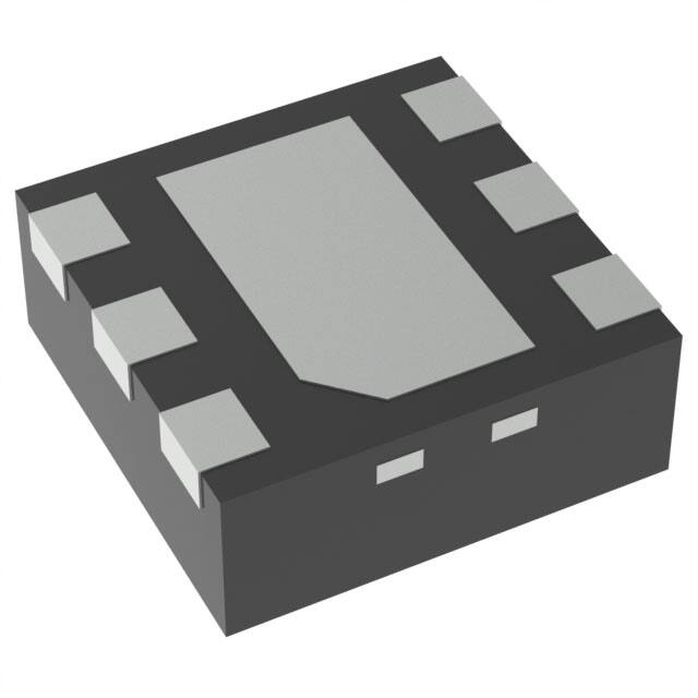


 工商网监
湘ICP备2023018690号
工商网监
湘ICP备2023018690号

