www.ti.com
Table of Contents
User’s Guide
TPS54A20 SWIFT™ Step-Down Converter Evaluation
Module User's Guide
ABSTRACT
This user’s guide contains information for the TPS54A20EVM-770 evaluation module (PWR770) as well as for
the TPS54A20 dc/dc converter. Also included are the performance specifications, the schematic, and the bill of
materials for the TPS54A20EVM-770.
Table of Contents
1 Introduction.............................................................................................................................................................................2
2 Test Setup and Results.......................................................................................................................................................... 4
3 Board Layout.........................................................................................................................................................................14
4 Schematic and Bill of Materials...........................................................................................................................................15
5 Revision History................................................................................................................................................................... 18
List of Figures
Figure 2-1. TPS54A20EVM-770 Efficiency..................................................................................................................................6
Figure 2-2. TPS54A20EVM-770 Low Current Efficiency............................................................................................................. 6
Figure 2-3. TPS54A20EVM-770 Load Regulation.......................................................................................................................7
Figure 2-4. TPS54A20EVM-770 Line Regulation........................................................................................................................ 7
Figure 2-5. TPS54A20EVM-770 Transient Response................................................................................................................. 8
Figure 2-6. TPS54A20EVM-770 Loop Response........................................................................................................................8
Figure 2-7. TPS54A20EVM-770 Output Ripple, 0 A Load...........................................................................................................9
Figure 2-8. TPS54A20EVM-770 Output Ripple, 5 A Load...........................................................................................................9
Figure 2-9. TPS54A20EVM-770 Output Ripple, 10 A Load.......................................................................................................10
Figure 2-10. TPS54A20EVM-770 Input Ripple, 0 A Load......................................................................................................... 10
Figure 2-11. TPS54A20EVM-770 Input Ripple, 5 A Load.......................................................................................................... 11
Figure 2-12. TPS54A20EVM-770 Input Ripple, 10 A Load........................................................................................................11
Figure 2-13. TPS54A20EVM-770 Start-Up Relative to VIN .......................................................................................................12
Figure 2-14. TPS54A20EVM-770 Start-Up Relative to Enable................................................................................................. 12
Figure 2-15. Thermal Image...................................................................................................................................................... 13
Figure 3-1. TPS54A20EVM-770 Top-Side Assembly................................................................................................................ 14
Figure 3-2. TPS54A20EVM-770 Top-Side Layout..................................................................................................................... 14
Figure 3-3. TPS54A20EVM-770 Internal Layer-1 Layout.......................................................................................................... 14
Figure 3-4. TPS54A20EVM-770 Internal Layer-2 Layout.......................................................................................................... 14
Figure 3-5. TPS54A20EVM-770 Bottom-Side Layout............................................................................................................... 15
Figure 4-1. TPS54A20EVM-770 Schematic.............................................................................................................................. 16
List of Tables
Table 1-1. Input Voltage and Output Current Summary...............................................................................................................3
Table 1-2. TPS54A20EVM-770 Performance Specification Summary........................................................................................ 3
Table 2-1. EVM Connectors and Test Points............................................................................................................................... 4
Table 4-1. TPS54A20EVM-770 Bill of Materials........................................................................................................................ 16
Trademarks
All trademarks are the property of their respective owners.
SLVUAM8B – DECEMBER 2015 – REVISED AUGUST 2021
TPS54A20 SWIFT™ Step-Down Converter Evaluation Module User's Guide
Submit Document Feedback
Copyright © 2021 Texas Instruments Incorporated
1
�Introduction
www.ti.com
1 Introduction
1.1 Before You Begin
The following warnings and cautions are noted for the safety of anyone using or working close to the
TPS54A20EVM-770. Observe all safety precautions.
Warning
The TPS54A20EVM-770 circuit module may become hot during operation due
to dissipation of heat. Avoid contact with the board. Follow all applicable safety
procedures applicable to your laboratory.
Caution
Do not leave the EVM powered when unattended.
!
WARNING
The circuit module has signal traces, components, and component leads on the bottom of the board.
This may result in exposed voltages, hot surfaces or sharp edges. Do not reach under the board
during operation.
CAUTION
The circuit module may be damaged by over temperature. To avoid damage, monitor the
temperature during evaluation and provide cooling, as needed, for your system environment.
CAUTION
Some power supplies can be damaged by application of external voltages. If using more than
1 power supply, check your equipment requirements and use blocking diodes or other isolation
techniques, as needed, to prevent damage to your equipment.
2
TPS54A20 SWIFT™ Step-Down Converter Evaluation Module User's Guide
SLVUAM8B – DECEMBER 2015 – REVISED AUGUST 2021
Submit Document Feedback
Copyright © 2021 Texas Instruments Incorporated
�www.ti.com
Introduction
1.2 Background
The TPS54A20 dc/dc converter is a two-phase synchronous series capacitor buck converter designed to provide
up to a 10-A output. The input (VIN) is rated for 8 V to 14 V. Rated input voltage and output current range for the
evaluation module are given in Table 1-1. This evaluation module is designed to demonstrate the small printedcircuit-board areas that may be achieved when designing with the TPS54A20 regulator. The switching frequency
is externally set at a nominal 2 MHz for each side, 4 MHz effective. The high-side and low-side MOSFETs
are incorporated inside the TPS54A20 package along with the gate drive circuitry. The low drain-to-source
on-resistance of the MOSFET allows the TPS54A20 to achieve high efficiencies and helps keep the junction
temperature low at high output currents. The compensation components are internal to the integrated circuit (IC),
and an external divider allows for an adjustable output voltage. Additionally, the TPS54A20 provides adjustable
slow start and undervoltage lockout inputs. The absolute maximum input voltage is 15 V while switching and 17
V for non-switching conditions.
Table 1-1. Input Voltage and Output Current Summary
EVM
INPUT VOLTAGE RANGE
OUTPUT CURRENT
RANGE
TPS54A20EVM-770
VIN = 9.2 V to 14 V
0 A to 10 A
1.3 Performance Specification Summary
A summary of the TPS54A20EVM-770 performance specifications is provided in Table 1-2. Specifications are
given for an input voltage of VIN = 12 V and an output voltage of 1.2 V, unless otherwise specified. The
TPS54A20EVM-770 is designed and tested for VIN = 9.2 V to 14 V. The ambient temperature is 25°C for all
measurements, unless otherwise noted.
Table 1-2. TPS54A20EVM-770 Performance Specification Summary
SPECIFICATION
TEST CONDITIONS
VIN voltage range
MIN
TYP
MAX
9.2
12
14
UNIT
V
VIN start voltage
9.39
V
VIN stop voltage
9.14
V
Output voltage setpoint
1.2
Output current range
VIN = 9.2 V to 14 V
Line regulation
IO = 5 A, VIN = 9.2 V to 14 V
±0.04%
Load regulation
VIN = 12 V, IO = 0 A to 10 A
±0.03%
IO = 0 A to 9 A
Load transient response
IO = 9 A to 0 A
0
V
10
A
Voltage change
–60
mV
Recovery time
60
µs
Voltage change
60
mV
Recovery time
60
µs
Loop bandwidth
VIN = 12 V, IO = 5 A
280
kHz
Phase margin
VIN = 12 V , IO = 5 A
45
degree
Input ripple voltage
IO = 10 A
90
mVPP
Output ripple voltage
IO = 10 A
20
mVPP
Output rise time
512
Operating frequency
Maximum efficiency
2
TPS54A20EVM-770, VIN = 9 V, IO = 5 A
µs
MHz
84.7%
1.4 Modifications
These evaluation modules are designed to provide access to the features of the TPS54A20. Some modifications
can be made to this module.
1.4.1 Output Voltage Setpoint
The output voltage is set by the resistor divider network of R9 (R(TOP)) and R7 (R(BOT)). R7 is fixed at 14.3 kΩ.
To change the output voltage of the EVM, it is necessary to change the value of resistor R9. Changing the value
SLVUAM8B – DECEMBER 2015 – REVISED AUGUST 2021
TPS54A20 SWIFT™ Step-Down Converter Evaluation Module User's Guide
Submit Document Feedback
Copyright © 2021 Texas Instruments Incorporated
3
�Introduction
www.ti.com
of R9 can change the output voltage above the 0.508 V reference voltage VREF. The value of R9 for a specific
output voltage can be calculated using Equation 1.
R (TOP) =
R (BOT) x (VOUT - VREF )
VREF
(1)
1.4.2 On Time
The TON pin requires a resistor to set the nominal on-time and to support the input voltage feed forward circuit.
The resistance value used also influences the internal ramp in the controller. Use Equation 2 for selecting the
TON resistor.
R (TON) = 3 k + 15 k x VOUT
(2)
The RTON resistor selected for this design example is 22.1 kΩ. During startup, the converter uses the nominal
on-time programmed through TON. The phase lock loop (PLL) is only activated after startup is complete. When
the PLL is engaged, the on-time is adjusted. If the nominal on-time programmed through the TON pin is not
close to the on-time when the PLL is engaged, the SYNC range of the device may be reduced. The TON resistor
can also be adjusted to tune the controller. Lowering the RTON value will increase the internal ramp height. This
will reduce the converter’s sensitivity to noise and jitter but it will also reduce the transient response capabilities
of the converter.
1.4.3 Adjustable UVLO
The undervoltage lockout (UVLO) can be adjusted externally using R2 (REN(TOP)) and R3 (REN(BOT)). The EVM
is set for a start voltage of 9.385 V and a stop voltage of 9.144 V using R2 = 80.6 kΩ and R3 = 12.4 kΩ. Use
Equation 3 and Equation 4 to calculate required resistor values for different start and stop voltages. IEN(FALL) = 4
µA, IEN(RISE) = 1 µA and VEN = 1.23 V
REN(TOP) =
REN(BOT) =
VIN(RISE) - VIN(FALL)
IEN(FALL) - IEN(RISE)
(3)
REN(TOP) x VEN
VIN(FALL) - VEN + REN(TOP) x IEN(FALL)
(4)
2 Test Setup and Results
This section describes how to properly connect, set up, and use the TPS54A20EVM-770 evaluation module.
The section also includes test results typical for the evaluation module and covers efficiency, output voltage
regulation, load transients, loop response, output ripple, input ripple, and start-up.
2.1 Input/Output Connections
The TPS54A20EVM-770 is provided with input/output connectors and test points as shown in Table 2-1. A power
supply capable of supplying greater than 2 A must be connected to J1 through a pair of 20 AWG wires or
better. The load must be connected to J4 through a pair of 20 AWG wires or better. The maximum load current
capability is 10 A. Wire lengths must be minimized to reduce losses in the wires. Test-point TP1 provides a place
to monitor the VIN input voltages with TP2 providing a convenient ground reference. TP7 is used to monitor the
output voltage with TP8 as the ground reference.
Table 2-1. EVM Connectors and Test Points
Reference Designator
J1
VIN input voltage connector. (See Table 1-1 for VIN range).
J2
2-pin header for enable. Connect EN to ground to disable, open to enable.
J3
External VG+ header. To improve converter efficiency, an external 5V supply is recommended to be connected
to the VG+ pin (J3-2) to GND (J3-1).
J4
VOUT, 1.2 V at 10 A maximum.
TP1
4
Function
VIN test point.
TPS54A20 SWIFT™ Step-Down Converter Evaluation Module User's Guide
SLVUAM8B – DECEMBER 2015 – REVISED AUGUST 2021
Submit Document Feedback
Copyright © 2021 Texas Instruments Incorporated
�www.ti.com
Test Setup and Results
Table 2-1. EVM Connectors and Test Points (continued)
Reference Designator
Function
TP2
GND test point at VIN connector.
TP3
PGOOD test point.
TP4
SYNC test point.
TP5
VG+ test point.
TP6
Test point between voltage divider network and output. Used for loop response measurements.
TP7
Output voltage test point.
TP8
GND test point
TP9
Test point at gate of transient load circuit.
TP10
GND test point at input of transient load circuit.
TP11
Test point at top of transient load circuit load resistor
TP12
Test point at bottom (GND) of transient load circuit load resistor
TP13
Analog ground (AGND) test point.
SLVUAM8B – DECEMBER 2015 – REVISED AUGUST 2021
TPS54A20 SWIFT™ Step-Down Converter Evaluation Module User's Guide
Submit Document Feedback
Copyright © 2021 Texas Instruments Incorporated
5
�Test Setup and Results
www.ti.com
2.2 Efficiency
The efficiency of this EVM peaks at a load current of about 5 A and then decreases as the load current increases
toward full load. Figure 2-1 shows the efficiency for the TPS54A20EVM-770 at an ambient temperature of 25°C.
100
90
80
Efficiency (%)
70
60
50
40
30
20
VIN = 9V
VIN = 12V
VIN = 14V
10
0
0
1
2
3
4
5
Output Current (A)
6
7
8
9
10
D001
Figure 2-1. TPS54A20EVM-770 Efficiency
Figure 2-2 shows the efficiency for the TPS54A20EVM-770 using a semi-log scale to more easily show
efficiency at lower output currents. The ambient temperature is 25°C.
100
90
80
Efficiency (%)
70
60
50
40
30
20
VIN = 9V
VIN = 12V
VIN = 14V
10
0
0.001
0.01
0.1
Output Current (A)
1
10
D002
Figure 2-2. TPS54A20EVM-770 Low Current Efficiency
The efficiency may be lower at higher ambient temperatures, due to temperature variation in the drain-to-source
resistance of the internal MOSFET.
6
TPS54A20 SWIFT™ Step-Down Converter Evaluation Module User's Guide
SLVUAM8B – DECEMBER 2015 – REVISED AUGUST 2021
Submit Document Feedback
Copyright © 2021 Texas Instruments Incorporated
�www.ti.com
Test Setup and Results
2.3 Output Voltage Load Regulation
Figure 2-3 shows the load regulation for the TPS54A20EVM-770.
1
0.8
0.6
Load Regulation (%)
0.4
0.2
0
-0.2
-0.4
-0.6
-0.8
-1
0
1
2
3
4
5
Output Current (A)
6
7
8
9
10
D003
Figure 2-3. TPS54A20EVM-770 Load Regulation
Measurements are given for an ambient temperature of 25°C.
2.4 Output Voltage Line Regulation
Figure 2-4 shows the line regulation for the TPS54A20EVM-770.
0.5
0.4
0.3
Line Regulation (%)
0.2
0.1
0
-0.1
-0.2
-0.3
-0.4
-0.5
9
10
11
12
Input Voltage (V)
13
14
D004
Figure 2-4. TPS54A20EVM-770 Line Regulation
SLVUAM8B – DECEMBER 2015 – REVISED AUGUST 2021
TPS54A20 SWIFT™ Step-Down Converter Evaluation Module User's Guide
Submit Document Feedback
Copyright © 2021 Texas Instruments Incorporated
7
�Test Setup and Results
www.ti.com
2.5 Load Transients
Figure 2-5 shows the TPS54A20EVM-770 response to load transients. The current step is from 0 A to 9 A. The
current step slew rate is 9 A/µs. Total peak-to-peak voltage variation is as shown, including ripple and noise on
the output. The transient waveform is measured using the on-board fast transient circuit.
CAUTION
Q1 may get hot. Limit the power dissipation to 3W or less. Use low duty cycles.
VO = 50 mV / div (ac coupled)
IO = 5 A / div
Load step = 0 A - 9 A, slew rate = 9 A / µsec
Time = 50 µsec / div
Figure 2-5. TPS54A20EVM-770 Transient Response
2.6 Loop Characteristics
60
180
50
150
40
120
30
90
20
60
10
30
0
0
-10
-30
-20
-60
-30
-90
-40
-120
-50
-60
100
Phase (Degrees)
Gain (dB)
Figure 2-6 shows the TPS54A20EVM-770 loop-response characteristics. Gain and phase plots are shown for
VIN voltage of 12 V. Load current for the measurement is 5 A.
-150
200 300 500
1000 2000
5000 10000 20000
Frequency (Hz)
50000100000
-180
1000000
EVMU
Figure 2-6. TPS54A20EVM-770 Loop Response
8
TPS54A20 SWIFT™ Step-Down Converter Evaluation Module User's Guide
SLVUAM8B – DECEMBER 2015 – REVISED AUGUST 2021
Submit Document Feedback
Copyright © 2021 Texas Instruments Incorporated
�www.ti.com
Test Setup and Results
2.7 Output Voltage Ripple
Figure 2-7, Figure 2-8, and Figure 2-9 show the TPS54A20EVM-770 output voltage ripple. The load currents are
0 A, 5 A and 10 A. VIN = 12 V. The ripple voltage is measured directly across TP7 and TP8.
VO = 20 mV / div (ac coupled)
SWA = 5 V / div
SWB = 5 V / div
Time = 200 nsec / div
Figure 2-7. TPS54A20EVM-770 Output Ripple, 0 A Load
VO = 20 mV / div (ac coupled)
SWA = 5 V / div
SWB = 5 V / div
Time = 200 nsec / div
Figure 2-8. TPS54A20EVM-770 Output Ripple, 5 A Load
SLVUAM8B – DECEMBER 2015 – REVISED AUGUST 2021
TPS54A20 SWIFT™ Step-Down Converter Evaluation Module User's Guide
Submit Document Feedback
Copyright © 2021 Texas Instruments Incorporated
9
�Test Setup and Results
www.ti.com
VO = 20 mV / div (ac coupled)
SWA = 5 V / div
SWB = 5 V / div
Time = 200 nsec / div
Figure 2-9. TPS54A20EVM-770 Output Ripple, 10 A Load
2.8 Input Voltage Ripple
Figure 2-10, Figure 2-11 and Figure 2-12 show the TPS54A20EVM-770 input voltage ripple. The load currents
are 0 A, 5 A and 10 A. VIN = 12 V. The ripple voltage is measured directly across TP1 and TP2.
VI = 50 mV / div (ac coupled)
SWA = 5 V / div
SWB = 5 V / div
Time = 200 nsec / div
Figure 2-10. TPS54A20EVM-770 Input Ripple, 0 A Load
10
TPS54A20 SWIFT™ Step-Down Converter Evaluation Module User's Guide
SLVUAM8B – DECEMBER 2015 – REVISED AUGUST 2021
Submit Document Feedback
Copyright © 2021 Texas Instruments Incorporated
�www.ti.com
Test Setup and Results
VI = 50 mV / div (ac coupled)
SWA = 5 V / div
SWB = 5 V / div
Time = 200 nsec / div
Figure 2-11. TPS54A20EVM-770 Input Ripple, 5 A Load
VI = 50 mV / div (ac coupled)
SWA = 5 V / div
SWB = 5 V / div
Time = 200 nsec / div
Figure 2-12. TPS54A20EVM-770 Input Ripple, 10 A Load
SLVUAM8B – DECEMBER 2015 – REVISED AUGUST 2021
TPS54A20 SWIFT™ Step-Down Converter Evaluation Module User's Guide
Submit Document Feedback
Copyright © 2021 Texas Instruments Incorporated
11
�Test Setup and Results
www.ti.com
2.9 Powering Up
Figure 2-13 and Figure 2-14 show the start-up waveforms for the TPS54A20EVM-770. In Figure 2-13, the output
voltage ramps up as soon as the input voltage reaches the UVLO threshold as set by the R2 and R3 resistor
divider network. In Figure 2-14, the input voltage is initially applied and the output is inhibited by using a jumper
at J2 to tie EN to GND. When the jumper is removed, EN is released. When the EN voltage reaches the
enable-threshold voltage, the start-up sequence begins and the output voltage ramps up to the externally set
value of 1.2 V. The input voltage for these plots is 12 V and the load is 1 Ω.
VIN = 10=0 V / div
EN = 1 V / div
VO = 500 mV / div
Time = 2 msec / div
Figure 2-13. TPS54A20EVM-770 Start-Up Relative to VIN
VIN = 10=0 V / div
EN = 1 V / div
VO = 500 mV / div
Time = 2 msec / div
Figure 2-14. TPS54A20EVM-770 Start-Up Relative to Enable
12
TPS54A20 SWIFT™ Step-Down Converter Evaluation Module User's Guide
SLVUAM8B – DECEMBER 2015 – REVISED AUGUST 2021
Submit Document Feedback
Copyright © 2021 Texas Instruments Incorporated
�www.ti.com
Test Setup and Results
2.10 Thermal Image
The EVM thermal image is shown in Figure 2-15. The input voltage is 12 V and the output current is 10A. The
EVM was allowed to operate at full 10 A load for > 45 minutes before the image was captured.
Maximum Case Temperature = 76.3 °C
Figure 2-15. Thermal Image
SLVUAM8B – DECEMBER 2015 – REVISED AUGUST 2021
TPS54A20 SWIFT™ Step-Down Converter Evaluation Module User's Guide
Submit Document Feedback
Copyright © 2021 Texas Instruments Incorporated
13
�Board Layout
www.ti.com
3 Board Layout
This section provides a description of the TPS54A20EVM-770 board layout and layer illustrations.
3.1 Layout
The board layout for the TPS54A20EVM-770 is shown in Figure 3-1 through Figure 3-5. The top-side layer of the
EVM is laid out in a manner typical of a user application. The top, bottom, and internal layers are 2-oz. copper.
The top layer contains the main power traces for VIN, VOUT, SWA and SWB. Also on the top layer are
connections for the remaining pins of the TPS54A20 and a large area filled with ground. The internal layer-1
is dedicated ground plane. The internal layer-2 contain an additional large ground copper area as well as an
additional VOUT copper fill. The bottom layer is another ground plane with an additional trace for the output
voltage feedback. The top-side ground traces are connected to the bottom and internal ground planes with
multiple vias placed around the board including five vias directly under the TPS54A20 device to provide a
thermal path from the top-side ground plane to the bottom-side ground plane.
The input decoupling capacitors and bootstrap capacitor are all located as close to the IC as possible.
Additionally, the voltage setpoint resistor divider components are kept close to the IC. The voltage divider
network ties to the output voltage at the point of regulation, the copper VOUT trace at the TP7 test point. For the
TPS54A20, an additional input bulk capacitor may be required, depending on the EVM connection to the input
supply. Critical analog circuits such as the voltage set point divider, frequency set resistor, and compensation
components are terminated to ground using a wide ground trace separate from the power ground pour.
14
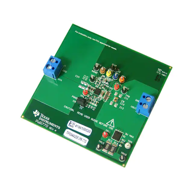
Figure 3-1. TPS54A20EVM-770 Top-Side Assembly
Figure 3-2. TPS54A20EVM-770 Top-Side Layout
Figure 3-3. TPS54A20EVM-770 Internal Layer-1
Layout
Figure 3-4. TPS54A20EVM-770 Internal Layer-2
Layout
TPS54A20 SWIFT™ Step-Down Converter Evaluation Module User's Guide
SLVUAM8B – DECEMBER 2015 – REVISED AUGUST 2021
Submit Document Feedback
Copyright © 2021 Texas Instruments Incorporated
�www.ti.com
Schematic and Bill of Materials
Figure 3-5. TPS54A20EVM-770 Bottom-Side Layout
4 Schematic and Bill of Materials
This section presents the TPS54A20EVM-770 schematic and bill of materials.
SLVUAM8B – DECEMBER 2015 – REVISED AUGUST 2021
TPS54A20 SWIFT™ Step-Down Converter Evaluation Module User's Guide
Submit Document Feedback
Copyright © 2021 Texas Instruments Incorporated
15
�Schematic and Bill of Materials
www.ti.com
4.1 Schematic
Figure 4-1 is the schematic for the TPS54A20EVM-770.
TP1
J1
2
1
Vin = 9.2 V - 14 V
DNPC22
47uF
25V
DNPC23
47uF
25V
C24
22uF
35V
C1
10uF
25V
C2
TP2
10uF
25V
U1
VIN
PGND
3
TP3
R2
80.6k
VG+
R6
TP4PGOOD 15
47.5k
SYNC
14
SSFSEL 6
EN
4
J2
2
1
TP5
J3
R3
R4
22.1k
12.4k DNP
C3
1uF
16V
5
VGA
7
TON
19
VG+ 16
2
1
R1
DNP
47.0k
ILIM
R5
22.1k
C4
1uF
10V 17
VIN
BOOTA
PGOOD
SYNC
SS/FSEL
EN
SCAP
SCAP
NC
SWA
8 BTA
9
20
C5
0.047uF
10V
SCAP
C6
2.2uF
16V SWA
11
13
L1
220nH
ILIM
TP7
VGA
BOOTB
TON
C7
0.047uF
10V
SWB
VG+
SWB
VG-
FB
12
18
TP8
L2
220nH R9
FB
1
AGND
PGND
AGND
PGND
C10
47uF
10V
DNPC11
DNPC12
100uF
100uF
6.3V
6.3V
PGND
0
2
TP6
C8
R8
TPS54A20RNJR
3.32k
PGND
AGND
C9
47uF
10V
1
2
R10
20.0k
PGND
J4
Vout = 1.2 V, 10 A
10 BTB
TP13
R7
14.3k
22pF
50V
5,6,
7,8
TP9
Q1
4
1,2,3
AGND
TP10
R11
51.1
TP11
R12
0.02
R13
0.02
TP12
PGND
Figure 4-1. TPS54A20EVM-770 Schematic
4.2 Bill of Materials
Table 4-1 presents the bill of materials for the TPS54A20EVM-770.
Table 4-1. TPS54A20EVM-770 Bill of Materials
Designator
Quantity
PCB
1
C1, C2
2
10uF
CAP, CERM, 10 uF, 25 V, +/- 20%, X5R, 0603
C3
1
1uF
C4
1
1uF
C5, C7
2
C6
1
16
Value
Description
Package
Part Number
Manufacturer
PWR770
Any
0603
C1608X5R1E106M080AC
TDK
CAP, CERM, 1 uF, 16 V, +/- 10%, X7R, 0603
0603
C1608X7R1C105K080AC
TDK
CAP, CERM, 1 uF, 10 V, +/- 10%, X5R, 0402
0402
GRM155R61A105KE15D
MuRata
0.047uF
CAP, CERM, 0.047 uF, 10 V, +/- 10%, X5R, 0402
0402
C1005X5R1A473K050BA
TDK
2.2uF
CAP, CERM, 2.2 uF, 16 V, +/- 10%, X7R, 1206
1206
GRM31MR71C225KA35L
MuRata
Printed Circuit Board
TPS54A20 SWIFT™ Step-Down Converter Evaluation Module User's Guide
Copyright © 2021 Texas Instruments Incorporated
SLVUAM8B – DECEMBER 2015 – REVISED AUGUST 2021
Submit Document Feedback
�www.ti.com
Schematic and Bill of Materials
Table 4-1. TPS54A20EVM-770 Bill of Materials (continued)
Designator
Quantity
Value
Description
Package
Part Number
Manufacturer
C8
1
22pF
CAP, CERM, 22 pF, 50 V, +/- 5%, C0G/NP0, 0603
0603
06035A220JAT2A
AVX
C9, C10
2
47uF
CAP, CERM, 47 uF, 10 V, +/- 20%, X5R, 0805
0805
GRM21BR61A476ME15
MuRata
C24
1
22uF
CAP, CERM, 22 uF, 35 V, +/- 20%, X5R, 0805
0805
C2012X5R1V226M125AC
TDK
J1, J4
2
Terminal Block, 5.08 mm, 2x1, Brass, TH
2x1 5.08 mm Terminal Block
ED120/2DS
On-Shore Technology
J2, J3
2
Header, 100mil, 2x1, Gold, TH
Header, 100mil, 2x1, TH
HTSW-102-07-G-S
Samtec
L1, L2
2
220nH
Inductor, 220 nH, 7.2 A, 0.0075 ohm, SMD
3.2x2.5mm
MLA-FY12NR22N-M3-RU
Mag Layers
Q1
1
30V
MOSFET, N-CH, 30 V, 65 A, DQJ0008A (VSONP-8)
DQJ0008A
CSD17527Q5A
Texas Instruments
R2
1
80.6k
RES, 80.6 k, 1%, 0.1 W, 0603
0603
CRCW060380K6FKEA
Vishay-Dale
R3
1
12.4k
RES, 12.4 k, 1%, 0.1 W, 0603
0603
CRCW060312K4FKEA
Vishay-Dale
R5
1
22.1k
RES, 22.1 k, 1%, 0.1 W, 0603
0603
RC0603FR-0722K1L
Yageo America
R6
1
47.5k
RES, 47.5 k, 1%, 0.1 W, 0603
0603
RC0603FR-0747K5L
Yageo America
R7
1
14.3k
RES, 14.3 k, 1%, 0.1 W, 0603
0603
CRCW060314K3FKEA
Vishay-Dale
R8
1
3.32k
RES, 3.32 k, 1%, 0.1 W, 0603
0603
CRCW06033K32FKEA
Vishay-Dale
R9
1
20.0k
RES, 20.0 k, 1%, 0.1 W, 0603
0603
CRCW060320K0FKEA
Vishay-Dale
R10
1
0
RES, 0, 5%, 0.1 W, 0603
0603
ERJ-3GEY0R00V
Panasonic
R11
1
51.1
RES, 51.1, 0.1%, 0.1 W, 0603
0603
RT0603BRD0751R1L
Yageo America
R12, R13
2
0.02
RES, 0.02, 1%, 3 W, 2512
2512
CRA2512-FZ-R020ELF
Bourns
SH-J1
1
1x2
Shunt, 100mil, Gold plated, Black
Shunt
SNT-100-BK-G
Samtec
TP1, TP7, TP11
3
Test Point, Multipurpose, Red, TH
Red Multipurpose Testpoint
5010
Keystone
TP2, TP8, TP10, TP12, TP13 5
Test Point, Multipurpose, Black, TH
Black Multipurpose Testpoint
5011
Keystone
TP3
1
Test Point, Multipurpose, Blue, TH
Blue Multipurpose Testpoint
5127
Keystone
TP4
1
Test Point, Multipurpose, Orange, TH
Orange Multipurpose
Testpoint
5013
Keystone
TP5
1
Test Point, Multipurpose, Yellow, TH
Yellow Multipurpose Testpoint 5014
Keystone
TP6
1
Test Point, Multipurpose, Brown, TH
Brown Multipurpose Testpoint 5125
Keystone
TP9
1
Test Point, Multipurpose, White, TH
White Multipurpose Testpoint
5012
Keystone
U1
1
Small, 10MHz 10A, 8V to 14V Input, SWIFT Series Capacitor RNJ0020A
Step-Down Converter, RNJ0020A (VQFN-HR-20)
TPS54A20RNJR
Texas Instruments
C11, C12
0
100uF
CAP, CERM, 100 uF, 6.3 V, +/- 20%, X5R, 1206
1206
JMK316BJ107ML-T
Taiyo Yuden
C22, C23
0
47uF
CAP, CERM, 47 uF, 25 V, +/- 20%, X5R, 1206_190
1206_190
C3216X5R1E476M160AC
TDK
R1
0
47.0k
RES, 47.0 k, 1%, 0.1 W, 0603
0603
RC0603FR-0747KL
Yageo America
R4
0
22.1k
RES, 22.1 k, 1%, 0.1 W, 0603
0603
RC0603FR-0722K1L
Yageo America
SLVUAM8B – DECEMBER 2015 – REVISED AUGUST 2021
Submit Document Feedback
TPS54A20 SWIFT™ Step-Down Converter Evaluation Module User's Guide
Copyright © 2021 Texas Instruments Incorporated
17
�Revision History
www.ti.com
5 Revision History
NOTE: Page numbers for previous revisions may differ from page numbers in the current version.
Changes from Revision A (March 2019) to Revision B (August 2021)
Page
• Updated user's guide title................................................................................................................................... 2
• Updated the numbering format for tables, figures, and cross-references throughout the document. ................2
Changes from Revision * (December 2015) to Revision A (March 2019)
Page
• Changed 1 kΩ to 14.3 kΩ................................................................................................................................... 3
• Updated Figure 2-6 ............................................................................................................................................8
• Updated Figure 3-1 through Figure 3-5............................................................................................................ 14
• Updated Figure 4-1...........................................................................................................................................15
• Updated Table 4-1............................................................................................................................................ 16
18
TPS54A20 SWIFT™ Step-Down Converter Evaluation Module User's Guide
SLVUAM8B – DECEMBER 2015 – REVISED AUGUST 2021
Submit Document Feedback
Copyright © 2021 Texas Instruments Incorporated
�IMPORTANT NOTICE AND DISCLAIMER
TI PROVIDES TECHNICAL AND RELIABILITY DATA (INCLUDING DATA SHEETS), DESIGN RESOURCES (INCLUDING REFERENCE
DESIGNS), APPLICATION OR OTHER DESIGN ADVICE, WEB TOOLS, SAFETY INFORMATION, AND OTHER RESOURCES “AS IS”
AND WITH ALL FAULTS, AND DISCLAIMS ALL WARRANTIES, EXPRESS AND IMPLIED, INCLUDING WITHOUT LIMITATION ANY
IMPLIED WARRANTIES OF MERCHANTABILITY, FITNESS FOR A PARTICULAR PURPOSE OR NON-INFRINGEMENT OF THIRD
PARTY INTELLECTUAL PROPERTY RIGHTS.
These resources are intended for skilled developers designing with TI products. You are solely responsible for (1) selecting the appropriate
TI products for your application, (2) designing, validating and testing your application, and (3) ensuring your application meets applicable
standards, and any other safety, security, regulatory or other requirements.
These resources are subject to change without notice. TI grants you permission to use these resources only for development of an
application that uses the TI products described in the resource. Other reproduction and display of these resources is prohibited. No license
is granted to any other TI intellectual property right or to any third party intellectual property right. TI disclaims responsibility for, and you
will fully indemnify TI and its representatives against, any claims, damages, costs, losses, and liabilities arising out of your use of these
resources.
TI’s products are provided subject to TI’s Terms of Sale or other applicable terms available either on ti.com or provided in conjunction with
such TI products. TI’s provision of these resources does not expand or otherwise alter TI’s applicable warranties or warranty disclaimers for
TI products.
TI objects to and rejects any additional or different terms you may have proposed. IMPORTANT NOTICE
Mailing Address: Texas Instruments, Post Office Box 655303, Dallas, Texas 75265
Copyright © 2022, Texas Instruments Incorporated
�


 工商网监
湘ICP备2023018690号
工商网监
湘ICP备2023018690号
