Product
Folder
Order
Now
Support &
Community
Tools &
Software
Technical
Documents
TPS61088
SLVSCM8C – MAY 2015 – REVISED FEBRUARY 2019
TPS61088 10-A Fully-Integrated Synchronous Boost Converter
1 Features
3 Description
•
•
•
•
The TPS61088 is a high power density, fully
integrated synchronous boost converter with a 11-mΩ
power switch and a 13-mΩ rectifier switch to provide
a high efficiency and small size solution in portable
systems. The TPS61088 has wide input voltage
range from 2.7 V to 12 V to support applications with
single cell or two cell Lithium batteries. The device
has 10-A switch current capability and is capable of
providing an output voltage up to 12.6 V.
1
•
•
•
•
•
•
•
•
•
•
Input Voltage Range: 2.7 to 12 V
Output Voltage Range: 4.5 to 12.6 V
10-A Switch Current
Up to 91% Efficiency at VIN = 3.3 V, VOUT = 9 V,
and IOUT = 3 A
Mode Selection Between PFM Mode and Forced
PWM Mode at Light Load
1.0 µA Current into VIN Pin during Shutdown
Resistor-Programmable Switch Peak Current Limit
Adjustable Switching Frequency: 200 kHz to 2.2
MHz
Programmable Soft Start
Output Overvoltage Protection at 13.2 V
Cycle-by-Cycle Overcurrent Protection
Thermal Shutdown
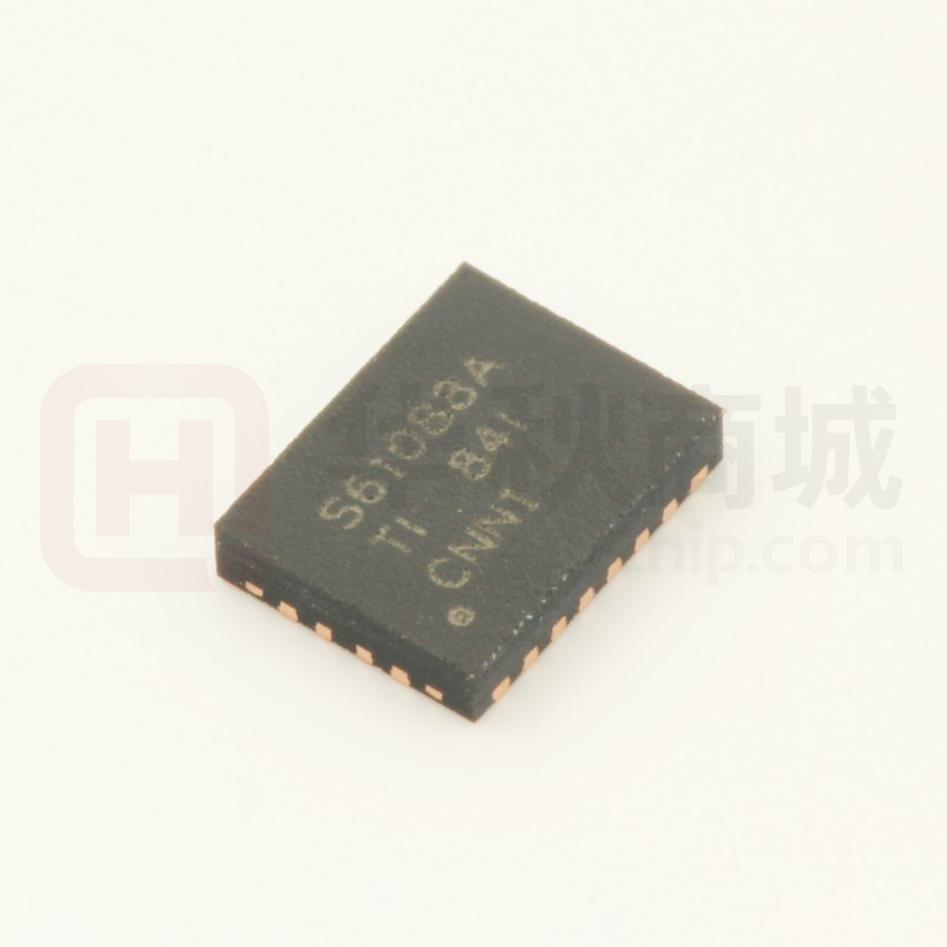
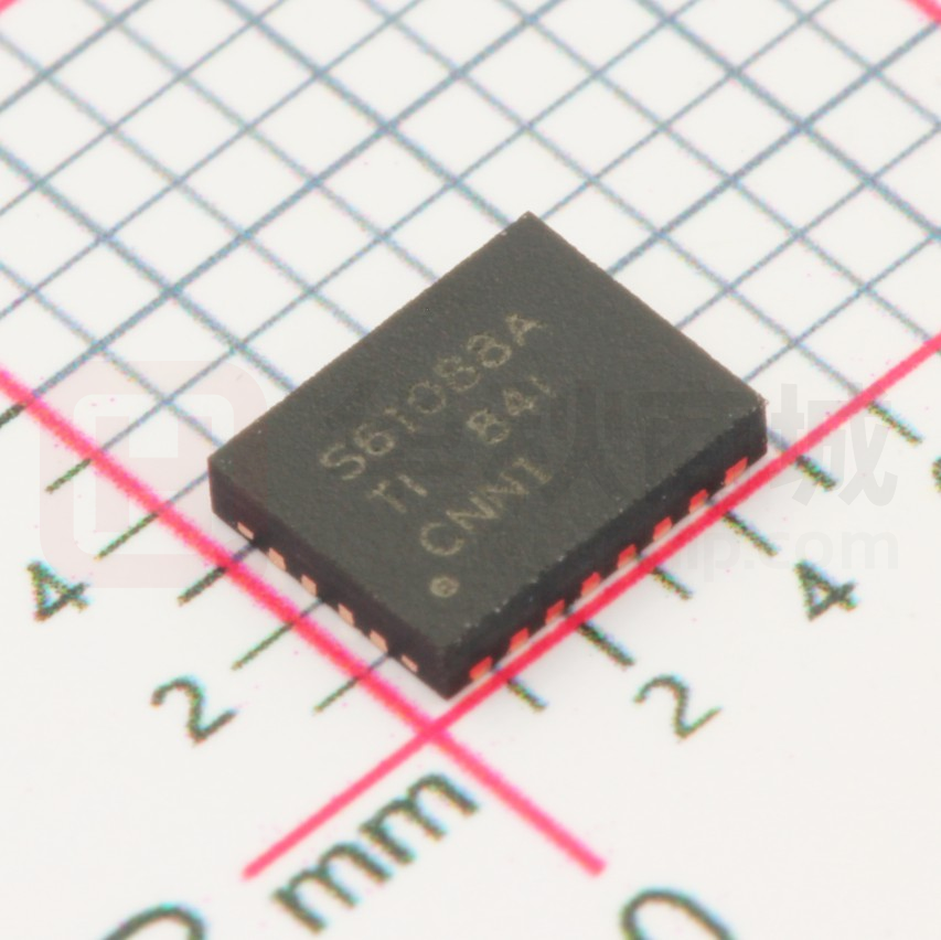
4.50-mm × 3.50-mm 20-Pin VQFN Package
Create a Custom Design Using the TPS61088
with the WEBENCH Power Designer
2 Applications
•
•
•
•
•
Portable POS terminal
Bluetooth™ Speaker
E-Cigarette
Thunderbolt Interface
Quick Charge Power Bank
The TPS61088 uses adaptive constant off-time peak
current control topology to regulate the output
voltage. In moderate to heavy load condition, the
TPS61088 works in the pulse width modulation
(PWM) mode. In light load condition, the device has
two operation modes selected by the MODE pin. One
is the pulse frequency modulation (PFM) mode to
improve the efficiency and another one is the forced
PWM mode to avoid application problems caused by
low switching frequency. The switching frequency in
the PWM mode is adjustable ranging from 200 kHz to
2.2 MHz by an external resistor. The TPS61088 also
implements a programmable soft-start function and
an adjustable switching peak current limit function. In
addition, the device provides 13.2-V output
overvoltage protection, cycle-by-cycle overcurrent
protection, and thermal shutdown protection.
The TPS61088 is available in a 4.50-mm × 3.50-mm
20-pin VQFN package.
Device Information(1)
PART NUMBER
TPS61088
PACKAGE
BODY SIZE (NOM)
VQFN (20)
4.50 mm × 3.50 mm
(1) For all available packages, see the orderable addendum at
the end of the data sheet.
Typical Application Circuit
C6
L1
VIN
SW
BOOT
VOUT
VOUT
C1
R3
C2
VIN
R2
FB
R5
VCC
C3
ON
OFF
C4
R1
FSW
C5
COMP
R4
EN
ILIM
PGND
SS
AGND
MODE
C7
1
An IMPORTANT NOTICE at the end of this data sheet addresses availability, warranty, changes, use in safety-critical applications,
intellectual property matters and other important disclaimers. PRODUCTION DATA.
�TPS61088
SLVSCM8C – MAY 2015 – REVISED FEBRUARY 2019
www.ti.com
Table of Contents
1
2
3
4
5
6
7
Features ..................................................................
Applications ...........................................................
Description .............................................................
Revision History.....................................................
Pin Configuration and Functions .........................
Specifications.........................................................
1
1
1
2
3
4
6.1
6.2
6.3
6.4
6.5
6.6
4
4
4
4
5
6
Absolute Maximum Ratings ......................................
ESD Ratings..............................................................
Recommended Operating Conditions.......................
Thermal Information ..................................................
Electrical Characteristics...........................................
Typical Characteristics ..............................................
Detailed Description .............................................. 8
7.1
7.2
7.3
7.4
Overview ................................................................... 8
Functional Block Diagram ......................................... 9
Feature Description................................................... 9
Device Functional Modes........................................ 11
8
Application and Implementation ........................ 13
8.1 Application Information............................................ 13
8.2 Typical Application .................................................. 13
9 Power Supply Recommendations...................... 20
10 Layout................................................................... 20
10.1 Layout Guidelines ................................................. 20
10.2 Layout Example .................................................... 20
10.3 Thermal Considerations ........................................ 21
11 Device and Documentation Support ................. 22
11.1
11.2
11.3
11.4
11.5
11.6
11.7
Custom Design with WEBENCH Tools.................
Receiving Notification of Documentation Updates
Device Support......................................................
Community Resources..........................................
Trademarks ...........................................................
Electrostatic Discharge Caution ............................
Glossary ................................................................
22
22
22
22
22
22
23
12 Mechanical, Packaging, and Orderable
Information ........................................................... 23
4 Revision History
NOTE: Page numbers for previous revisions may differ from page numbers in the current version.
Changes from Revision B (September) to Revision C
Page
•
Corrected spelling of 'resister' to 'resistor' in the Pin Functions table. ................................................................................... 3
•
Added caption to Functional Block Diagram as auto-number Figure 10................................................................................ 9
•
Added cross-reference hyperlink in the Enable and Startup section pointing to C7 reference in Figure 12. ........................ 9
•
Inserted missing cross-reference hyperlink in Setting Output Voltage section pointing to Figure 12 circuit in the
Typical Application section. .................................................................................................................................................. 14
Changes from Revision A (May 2015) to Revision B
•
Page
Added thermal information for EVM configuration ................................................................................................................. 4
Changes from Original (May 2015) to Revision A
Page
•
Updated device status to production data ............................................................................................................................. 1
•
Updated VCCLPH and VCCLPL typical voltage ............................................................................................................................ 5
•
Fixed legend of Figure 2 and Figure 4 from input to output .................................................................................................. 6
2
Submit Documentation Feedback
Copyright © 2015–2019, Texas Instruments Incorporated
Product Folder Links: TPS61088
�TPS61088
www.ti.com
SLVSCM8C – MAY 2015 – REVISED FEBRUARY 2019
5 Pin Configuration and Functions
VCC
AGND
RHL Package
20 Pin VQFN With Thermal Pad
Top View
ILIM
EN
FSW
COMP
SW
FB
VOUT
SW
RHL
VOUT
SW
SW
VOUT
PGND
MODE
BOOT
VIN
NC
SS
NC
Pin Functions
PIN
NAME
NUMBER
I/O
DESCRIPTION
VCC
1
O
Output of the internal regulator. A ceramic capacitor of more than 1.0 µF is required between
this pin and ground.
EN
2
I
Enable logic input. Logic high level enables the device. Logic low level disables the device
and turns it into shutdown mode.
FSW
3
I
The switching frequency is programmed by a resistor between this pin and the SW pin.
4, 5, 6, 7
I
The switching node pin of the converter. It is connected to the drain of the internal low-side
power MOSFET and the source of the internal high-side power MOSFET.
BOOT
8
O
Power supply for high-side MOSFET gate driver. A ceramic capacitor of 0.1 µF must be
connected between this pin and the SW pin
VIN
9
I
IC power supply input
SS
10
O
Soft-start programming pin. An external capacitor sets the ramp rate of the internal error
amplifier's reference voltage during soft-start
NC
11, 12
—
No connection inside the device. Connect these two pins to ground plane on the PCB for
good thermal dissipation
MODE
13
I
Operation mode selection pin for the device in light load condition. When this pin is connected
to ground, the device works in PWM mode. When this pin is left floating, the device works in
PFM mode.
VOUT
14, 15, 16
O
Boost converter output
FB
17
I
Voltage feedback. Connect to the center tape of a resistor divider to program the output
voltage.
COMP
18
O
Output of the internal error amplifier, the loop compensation network should be connected
between this pin and the AGND pin.
ILIM
19
O
Adjustable switch peak current limit. An external resistor should be connected between this
pin and the AGND pin.
AGND
20
—
Signal ground of the IC
PGND
21
—
Power ground of the IC. It is connected to the source of the low-side MOSFET.
SW
Submit Documentation Feedback
Copyright © 2015–2019, Texas Instruments Incorporated
Product Folder Links: TPS61088
3
�TPS61088
SLVSCM8C – MAY 2015 – REVISED FEBRUARY 2019
www.ti.com
6 Specifications
6.1 Absolute Maximum Ratings
over operating free-air temperature (unless otherwise noted)
(1)
MIN
MAX
BOOT
–0.3
SW + 7
VIN, SW, FSW, VOUT
–0.3
14.5
EN, VCC, SS, COMP, MODE
–0.3
7
ILIM, FB
–0.3
3.6
TJ
Operating junction temperature
–40
150
°C
Tstg
Storage temperature
–65
150
°C
Voltage (2)
(1)
(2)
UNIT
V
Stresses beyond those listed under Absolute Maximum Ratings may cause permanent damage to the device. These are stress ratings
only, which do not imply functional operation of the device at these or any other conditions beyond those indicated under Recommended
Operating Conditions. Exposure to absolute-maximum-rated conditions for extended periods may affect device reliability.
All voltage values are with respect to network ground terminal.
6.2 ESD Ratings
VALUE
Electrostatic
discharge
V(ESD)
(1)
(2)
Human body model (HBM), per ANSI/ESDA/JEDEC JS-001, all pins (1)
±2000
Charged device model (CDM), per JEDEC specification JESD22-C101, all pins (2)
±500
UNIT
V
JEDEC document JEP155 states that 500-V HBM allows safe manufacturing with a standard ESD control process.
JEDEC document JEP157 states that 250-V CDM allows safe manufacturing with a standard ESD control process.
6.3 Recommended Operating Conditions
over operating free-air temperature range (unless otherwise noted)
MIN
NOM
MAX
VIN
Input voltage range
2.7
12
VOUT
Output voltage range
4.5
12.6
L
Inductance, effective value
CI
Input capacitance, effective value
10
CO
Output capacitance, effective value
6.8
TJ
Operating junction temperature
–40
0.47
UNIT
V
V
2.2
10
µH
47
1000
µF
125
°C
µF
6.4 Thermal Information
THERMAL METRIC
(1)
TPS61088
TPS61088
RHL 20 Pins
RHL 20 Pins
Standard
EVM
UNIT
RθJA
Junction-to-ambient thermal resistance
38.8
29.7
°C/W
RθJC(top)
Junction-to-case (top) thermal resistance
39.8
N/A
°C/W
RθJB
Junction-to-board thermal resistance
15.5
N/A
°C/W
ψJT
Junction-to-top characterization parameter
0.6
0.5
°C/W
ψJB
Junction-to-board characterization parameter
15.5
9.8
°C/W
RθJC(bot)
Junction-to-case (bottom) thermal resistance
3.1
N/A
°C/W
(1)
4
For more information about traditional and new thermal metrics, see the Semiconductor and IC Package Thermal Metrics application
report, SPRA953.
Submit Documentation Feedback
Copyright © 2015–2019, Texas Instruments Incorporated
Product Folder Links: TPS61088
�TPS61088
www.ti.com
SLVSCM8C – MAY 2015 – REVISED FEBRUARY 2019
6.5 Electrical Characteristics
Minimum and maximum values are at VIN = 2.7 V to 5.5 V and TJ = -40°C to 125°C. Typical values are at VIN = 3.6 V and TJ =
25°C
PARAMETER
TEST CONDITIONS
MIN
TYP
MAX
UNIT
POWER SUPPLY
VIN
Input voltage range
VIN_UVLO
Undervoltage lockout (UVLO)
threshold
VIN_HYS
VIN UVLO hysteresis
VCC_UVLO
UVLO threshold
IQ
Operating quiescent current from the
VIN pin
Operating quiescent current from the
VOUT pin
2.7
VIN rising
VIN falling
2.4
VCC falling
IC enabled, VEN = 2 V, no load, RILIM = 100
kΩ , VFB = 1.3 V, VOUT = 12 V, TJ up to 85°C
ISD
Shutdown current into the VIN pin
IC disabled, VEN = 0 V, no load, no feedback
resistor divider connected to the VOUT pin, TJ
up to 85°C
VCC
VCC regulation
IVCC = 5 mA, VIN = 8 V
12
V
2.7
V
2.5
V
200
mV
2.1
V
1
3
µA
110
250
µA
1
3
µA
5.8
V
EN AND MODE INPUT
VENH
EN high threshold voltage
VCC = 6 V
VENL
EN low threshold voltage
VCC = 6 V
REN
EN internal pull-down resistance
VCC = 6 V
VMODEH
MODE high threshold voltage
VCC = 6 V
VMODEL
MODE low threshold voltage
VCC = 6 V
RMODE
MODE internal pull-up resistance
VCC = 6 V
1.2
0.4
V
V
800
kΩ
4.0
1.5
V
V
800
kΩ
OUTPUT
VOUT
Output voltage range
VREF
Reference voltage at the FB pin
ILKG_FB
FB pin leakage current
ISS
Soft-start charging current
4.5
PWM mode
1.186
PFM mode
12.6
1.204
1.222
1.212
VFB = 1.2 V
100
V
V
nA
5
μA
20
µA
µA
ERROR AMPLIFIER
ISINK
COMP pin sink current
VFB = VREF +200 mV, VCOMP = 1.5 V
ISOURCE
COMP pin source current
VFB = VREF –200 mV, VCOMP = 1.5 V
20
VCCLPH
High clamp voltage at the COMP pin
VFB = 1 V, RILIM = 100 kΩ
2.3
VCCLPL
Low clamp voltage at the COMP pin
VFB = 1.5 V, RILIM = 100 kΩ, MODE pin floating
1.4
GEA
Error amplifier transconductance
VCOMP = 1.5 V
190
V
µA/V
POWER SWITCH
RDS(on)
High-side MOSFET on-resistance
VCC = 6 V
13
18
mΩ
Low-side MOSFET on-resistance
VCC = 6 V
11
16.5
mΩ
CURRENT LIMIT
ILIM
VILIM
Peak switch current limit in PFM
mode
RILIM = 100 kΩ, VCC = 6 V, MODE pin floating
10.6
11.9
13
A
Peak switch current limit in FPWM
mode
RILIM = 100 kΩ, VCC = 6 V, MODE pin short to
ground
9.0
10.3
11.4
A
Reference voltage at the ILIM pin
1.204
V
SWITCHING FREQUENCY
ƒSW
Switching frequency
RFREQ = 301 kΩ, VIN = 3.6 V, VOUT = 12 V
500
tON_min
Minimum on-time
RFREQ = 301 kΩ, VIN = 3.6 V, VOUT = 12 V
90
180
kHz
ns
13.2
13.6
V
PROTECTION
VOVP
Output overvoltage protection
threshold
VOUT rising
12.7
Submit Documentation Feedback
Copyright © 2015–2019, Texas Instruments Incorporated
Product Folder Links: TPS61088
5
�TPS61088
SLVSCM8C – MAY 2015 – REVISED FEBRUARY 2019
www.ti.com
Electrical Characteristics (continued)
Minimum and maximum values are at VIN = 2.7 V to 5.5 V and TJ = -40°C to 125°C. Typical values are at VIN = 3.6 V and TJ =
25°C
PARAMETER
VOVP_HYS
Output overvoltage protection
hysteresis
TEST CONDITIONS
MIN
TYP
MAX
UNIT
VOUT falling below VOVP
0.25
V
150
°C
20
°C
THERMAL SHUTDOWN
TSD
Thermal shutdown threshold
TJ rising
TSD_HYS
Thermal shutdown hysteresis
TJ falling below TSD
100%
100%
90%
90%
80%
80%
70%
70%
60%
60%
Efficiency
Efficiency
6.6 Typical Characteristics
50%
40%
20%
20%
3-V Input
3.6-V Input
4.2-V Input
10%
0.001
0.01
0.1 0.2 0.5 1
Output Current (A)
0
0.0001
2 3 5 710
90%
90%
80%
80%
70%
70%
60%
50%
40%
0.01
0.1 0.2 0.5 1
Output Current (A)
2 3 5 710
D002
Figure 2. Efficiency vs Output Current, VIN = 3.6 V, FPWM
100%
Efficiency
Efficiency
0.001
D001
100%
60%
50%
40%
3-V Input
3.6-V Input
4.2-V Input
30%
20%
0.0001
5-V Output
9-V Output
12-V Output
10%
Figure 1. Efficiency vs Output Current, VOUT = 9 V, FPWM
0.001
0.01
0.1 0.2 0.5 1
Output Current (A)
5-V Output
9-V Output
12-V Output
30%
2 3 5 710
20%
0.0001
D003
Figure 3. Efficiency vs Output Current, VOUT = 9 V, PFM
6
40%
30%
30%
0
0.0001
50%
0.001
0.01
0.1 0.2 0.5 1
Output Current (A)
2 3 5 710
D004
Figure 4. Efficiency vs Output Current, VIN = 3.6 V, PFM
Submit Documentation Feedback
Copyright © 2015–2019, Texas Instruments Incorporated
Product Folder Links: TPS61088
�TPS61088
www.ti.com
SLVSCM8C – MAY 2015 – REVISED FEBRUARY 2019
Typical Characteristics (continued)
2500
14
PFM Mode
FPWM Mode
12
Frequency (kHz)
Current Limit (A)
2000
10
8
6
1500
1000
4
500
2
0
80
0
120
160
200
240
Resistance (k:)
280
320
0
360
100
200
300
D005
Figure 5. Current Limit vs Setting Resistance
400 500 600
Resistance (k:)
700
800
900
D006
Figure 6. Switching Frequency vs Setting Resistance
140
1.21
1.209
120
Quiescent Current (PA)
Reference Votlage (V)
1.208
1.207
1.206
1.205
1.204
1.203
100
80
60
40
1.202
20
1.201
1.2
-40
-20
0
20
40
60
Temperature (°C)
80
100
120130
0
-40 -30 -20 -10
0
10 20 30 40 50 60 70 80 90
Temperature (°C)
D008
D007
Figure 7. Reference Voltage vs Temperature
Figure 8. Quiescent Current vs Temperature
1
0.9
Shutdown Current (PA)
0.8
0.7
0.6
0.5
0.4
0.3
0.2
0.1
0
-40
-20
0
20
40
Temperature (°C)
60
80
100
D009
Figure 9. Shutdown Current vs Temperature
Submit Documentation Feedback
Copyright © 2015–2019, Texas Instruments Incorporated
Product Folder Links: TPS61088
7
�TPS61088
SLVSCM8C – MAY 2015 – REVISED FEBRUARY 2019
www.ti.com
7 Detailed Description
7.1 Overview
The TPS61088 is a fully-integrated synchronous boost converter with a 11-mΩ power switch and a 13-mΩ
rectifier switch to output high power from a single cell or two-cell Lithium batteries. The device is capable of
providing an output voltage of 12.6 V and delivering up to 30-W power from a single cell Lithium battery.
The TPS61088 uses adaptive constant off-time peak current control topology to regulate the output voltage. In
moderate-to-heavy load condition, the TPS61088 works in the quasi-constant frequency pulse width modulation
(PWM) mode. The switching frequency in the PWM mode is adjustable ranging from 200 kHz to 2.2 MHz by an
external resistor. In light load condition, the device has two operation modes selected by the MODE pin. When
the MODE pin is left floating, the TPS61088 works in the pulse frequency modulation (PFM) mode. The PFM
mode brings high efficiency at the light load. When the MODE pin is short to ground, the TPS61088 works in the
forced PWM mode (FPWM). The FPWM mode can avoid the acoustic noise and other problems caused by the
low switching frequency. The TPS61088 implements cycle-by-cycle current limit to protect the device from
overload conditions during boost switching. The switch peak current limit is programmable by an external
resistor. The TPS61088 uses external loop compensation, which provides flexibility to use different inductors and
output capacitors. The adaptive off-time peak current control scheme gives excellent transient line and load
response with minimal output capacitance.
8
Submit Documentation Feedback
Copyright © 2015–2019, Texas Instruments Incorporated
Product Folder Links: TPS61088
�TPS61088
www.ti.com
SLVSCM8C – MAY 2015 – REVISED FEBRUARY 2019
7.2 Functional Block Diagram
L1
VIN
C3
C1
VIN
BOOT
SW
VOUT
VOUT
C2
Deadtime
Control Logic
Q
VCC
Shutdown
LDO
C4
PGND
Comp
R3
S
R
C5
Comp
CLMIT
FSW
FB
Comp
gm
R1
R4
SS
1/K
Comp
SW
VIN
COMP
Vref
R2
SS Vref
EN
C6
C7
Shutdown
Control
ON/
OFF
Shutdown
Vref
AGND
CLMIT
VOUT
OVP
VIN
UVLO
ILIM
Thermal
Shutdown
Mode
Selection
R5
MODE
Figure 10. Functional Block Diagram
7.3 Feature Description
7.3.1 Enable and Startup
The TPS61088 has an adjustable soft start function to prevent high inrush current during start-up. To minimize
the inrush current during start-up, an external capacitor, connected to the SS pin and charged with a constant
current, is used to slowly ramp up the internal positive input of the error amplifier. When the EN pin is pulled
high, the soft-start capacitor CSS (C7 in Figure 12) is charged with a constant current of 5 μA typically. During this
time, the SS pin voltage is compared with the internal reference (1.204 V), the lower one is fed into the internal
positive input of the error amplifier. The output of the error amplifier (which determines the inductor peak current
value) ramps up slowly as the SS pin voltage goes up. The soft-start phase is completed after the SS pin voltage
exceeds the internal reference (1.204 V). The larger the capacitance at the SS pin, the slower the ramp of the
output voltage and the longer the soft-start time. A 47-nF capacitor is usually sufficient for most applications.
When the EN pin is pulled low, the voltage of the soft-start capacitor is discharged to ground.
Submit Documentation Feedback
Copyright © 2015–2019, Texas Instruments Incorporated
Product Folder Links: TPS61088
9
�TPS61088
SLVSCM8C – MAY 2015 – REVISED FEBRUARY 2019
www.ti.com
Feature Description (continued)
Use Equation 1 to calculate the soft-start time.
VREF u CSS
t SS
ISS
where
•
•
•
•
tSS is the soft start time.
VREF is the internal reference voltage of 1.204 V.
CSS is the capacitance between the SS pin and ground.
ISS is the soft-start charging current of 5 µA.
(1)
7.3.2 Undervoltage Lockout (UVLO)
The UVLO circuit prevents the device from malfunctioning at low input voltage and the battery from excessive
discharge. The TPS61088 has both VIN UVLO function and VCC UVLO function. It disables the device from
switching when the falling voltage at the VIN pin trips the UVLO threshold VIN_UVLO , which is typically 2.4 V. The
device starts operating when the rising voltage at the VIN pin is 200-mV above the VIN_UVLO. It also disables the
device when the falling voltage at the VCC pin trips the UVLO threshold VCC_UVLO, which is typically 2.1 V.
7.3.3 Adjustable Switching Frequency
This device features a wide adjustable switching frequency ranging from 200 kHz to 2.2 MHz. The switching
frequency is set by a resistor connected between the FSW pin and the SW pin of the TPS61088. A resistor must
always be connected from the FSW pin to SW pin for proper operation. The resistor value required for a desired
frequency can be calculated using Equation 2.
V
1
4u(
tDELAY u OUT )
¦SW
9IN
RFREQ
CFREQ
where
•
•
•
•
•
•
RFREQ is the resistance connected between the FSW pin and the SW pin.
CFREQ = 23 pF
ƒSW is the desired switching frequency.
tDELAY = 89 ns
VIN is the input voltage.
VOUT is the output voltage.
(2)
7.3.4 Adjustable Peak Current Limit
To avoid an accidental large peak current, an internal cycle-by-cycle current limit is adopted. The low-side switch
is turned off immediately as soon as the switch current touches the limit. The peak switch current limit can be set
by a resistor at the ILIM pin to ground. The relationship between the current limit and the resistance depends on
the status of the MODE pin.
When the MODE pin is floating, namely the TPS61088 is set to work in the PFM mode at light load, use
Equation 3 to calculate the resistor value:
ILIM
1190000
RILIM
where
•
•
RILIM is the resistance between the ILIM pin and ground.
ILIM is the switch peak current limit.
(3)
When the resistor value is 100 kΩ, the typical current limit is 11.9 A.
When the MODE pin is connected to ground, namely the TPS61088 is set to work in the forced PWM mode at
light load, use Equation 4 to calculate the resistor value.
10
Submit Documentation Feedback
Copyright © 2015–2019, Texas Instruments Incorporated
Product Folder Links: TPS61088
�TPS61088
www.ti.com
SLVSCM8C – MAY 2015 – REVISED FEBRUARY 2019
Feature Description (continued)
ILIM
1190000
1.6
RILIM
(4)
When the resistor value is 100 kΩ. the typical current limit is 10.3 A.
Considering the device variation and the tolerance over temperature, the minimum current limit at the worst case
can be 1.3 A lower than the value calculated by above equations.
7.3.5 Overvoltage Protection
If the output voltage at the VOUT pin is detected above 13.2 V (typical value), the TPS61088 stops switching
immediately until the voltage at the VOUT pin drops the hysteresis value lower than the output overvoltage
protection threshold. This function prevents overvoltage on the output and secures the circuits connected to the
output from excessive overvoltage.
7.3.6 Thermal Shutdown
A thermal shutdown is implemented to prevent damages due to excessive heat and power dissipation. Typically,
the thermal shutdown happens at a junction temperature of 150°C. When the thermal shutdown is triggered, the
device stops switching until the junction temperature falls below typically 130°C, then the device starts switching
again.
7.4 Device Functional Modes
7.4.1 Operation
The synchronous boost converter TPS61088 operates at a quasi-constant frequency pulse width modulation
(PWM) in moderate to heavy load condition. Based on the VIN to VOUT ratio, a circuit predicts the required offtime of the switching cycle. At the beginning of each switching cycle, the low-side N-MOSFET switch, shown in
the Functional Block Diagram, is turned on, and the inductor current ramps up to a peak current that is
determined by the output of the internal error amplifier. After the peak current is reached, the current comparator
trips, and it turns off the low-side N-MOSFET switch and the inductor current goes through the body diode of the
high-side N-MOSFET in a dead-time duration. After the dead-time duration, the high-side N-MOSFET switch is
turned on. Because the output voltage is higher than the input voltage, the inductor current decreases. The highside switch is not turned off until the fixed off-time is reached. After a short dead-time duration, the low-side
switch turns on again and the switching cycle is repeated.
In light load condition, the TPS61088 implements two operation modes, PFM mode and forced PWM mode, to
meet different application requirements. The operation mode is set by the status of the MODE pin. When the
MODE pin is connected to ground, the device works in the forced PWM mode. When the MODE pin is left
floating, the device works in the PFM mode.
7.4.1.1 PWM Mode
In the forced PWM mode, the TPS61088 keeps the switching frequency unchanged in light load condition. When
the load current decreases, the output of the internal error amplifier decreases as well to keep the inductor peak
current down, delivering less power from input to output. When the output current further reduces, the current
through the inductor will decrease to zero during the off-time. The high-side N-MOSFET is not turned off even if
the current through the MOSFET is zero. Thus, the inductor current changes its direction after it runs to zero.
The power flow is from output side to input side. The efficiency will be low in this mode. But with the fixed
switching frequency, there is no audible noise and other problems which might be caused by low switching
frequency in light load condition.
7.4.1.2 PFM Mode
The TPS61088 improves the efficiency at light load with the PFM mode. When the converter operates in light
load condition, the output of the internal error amplifier decreases to make the inductor peak current down,
delivering less power to the load. When the output current further reduces, the current through the inductor will
decrease to zero during the off-time. Once the current through the high side N-MOSFET is zero, the high-side
MOSFET is turned off until the beginning of the next switching cycle. When the output of the error amplifier
continuously goes down and reaches a threshold with respect to the peak current of ILIM / 12, the output of the
Submit Documentation Feedback
Copyright © 2015–2019, Texas Instruments Incorporated
Product Folder Links: TPS61088
11
�TPS61088
SLVSCM8C – MAY 2015 – REVISED FEBRUARY 2019
www.ti.com
Device Functional Modes (continued)
error amplifier is clamped at this value and does not decrease any more. If the load current is smaller than what
the TPS61088 delivers, the output voltage increases above the nominal setting output voltage. The TPS61088
extends its off time of the switching period to deliver less energy to the output and regulate the output voltage to
0.7% higher than the nominal setting voltage. With the PFM operation mode, the TPS61088 keeps the efficiency
above 80% even when the load current decreases to 1 mA. In addition, the output voltage ripple is much smaller
at light load due to low peak current. Refer to Figure 11.
Output Voltage
PFM mode at light load
1.007 × VOUT_NOM
VOUT_NOM
PWM mode at heavy load
Figure 11. PFM Mode Diagram
12
Submit Documentation Feedback
Copyright © 2015–2019, Texas Instruments Incorporated
Product Folder Links: TPS61088
�TPS61088
www.ti.com
SLVSCM8C – MAY 2015 – REVISED FEBRUARY 2019
8 Application and Implementation
NOTE
Information in the following applications sections is not part of the TI component
specification, and TI does not warrant its accuracy or completeness. TI’s customers are
responsible for determining suitability of components for their purposes. Customers should
validate and test their design implementation to confirm system functionality.
8.1 Application Information
The TPS61088 is designed for outputting voltage up to 12.6 V with 10-A switch current capability to deliver more
than 30-W power. The TPS61088 operates at a quasi-constant frequency pulse-width modulation (PWM) in
moderate to heavy load condition. In light load condition, the converter can either operate in the PFM mode or in
the forced PWM mode according to the mode selection. The PFM mode brings high efficiency over entire load
range, but the PWM mode can avoid the acoustic noise as the switching frequency is fixed. The converter uses
the adaptive constant off-time peak current control scheme, which provides excellent transient line and load
response with minimal output capacitance. The TPS61088 can work with different inductor and output capacitor
combination by external loop compensation. It also supports adjustable switching frequency ranging from 200
kHz to 2.2 MHz.
8.2 Typical Application
C6
0.1 µF
L1
VOUT = 9 V
IOUT = 3 A
1.2 µH
VIN = 3.3 to 4.2 V
SW
BOOT
VOUT
R3
C9
1 µF
C4
3× 22 µF
R2
FSW
FB
255 k
C1
C2
2.2 µF
COMP
VCC
C3
ON
OFF
56 k
C8
VIN
10 µF
0.1 µF
R1
360 k
R5
C5
R4 100 k
EN
ILIM
PGND
SS
AGND
C7
47 nF
MODE
Figure 12. TPS61088 3.3 V to 9-V/3-A Output Converter
8.2.1 Design Requirements
Table 1. Design Parameters
Design Parameters
Example Values
Input voltage range
3.3 to 4.2 V
Output voltage
9V
Output voltage ripple
100 mV peak to peak
Output current rating
3A
Operating frequency
600 kHz
Operation mode at light load
PFM
Submit Documentation Feedback
Copyright © 2015–2019, Texas Instruments Incorporated
Product Folder Links: TPS61088
13
�TPS61088
SLVSCM8C – MAY 2015 – REVISED FEBRUARY 2019
www.ti.com
8.2.2 Detailed Design Procedure
8.2.2.1 Custom Design with WEBENCH Tools
Click here to create a custom design using the TPS61088 device with the WEBENCH® Power Designer.
1. Start by entering your VIN, VOUT and IOUT requirements.
2. Optimize your design for key parameters like efficiency, footprint and cost using the optimizer dial and
compare this design with other possible solutions from Texas Instruments.
3. WEBENCH Power Designer provides you with a customized schematic along with a list of materials with real
time pricing and component availability.
4. In most cases, you will also be able to:
– Run electrical simulations to see important waveforms and circuit performance,
– Run thermal simulations to understand the thermal performance of your board,
– Export your customized schematic and layout into popular CAD formats,
– Print PDF reports for the design, and share your design with colleagues.
5. Get more information about WEBENCH tools at www.ti.com/webench.
8.2.2.2 Setting Switching Frequency
The switching frequency is set by a resistor connected between the FSW pin and the SW pin of the TPS61088.
The resistor value required for a desired frequency can be calculated using Equation 5.
V
1
4u(
tDELAY u OUT )
¦SW
9IN
RFREQ
CFREQ
where
•
•
•
•
•
•
RFREQ is the resistance connected between the FSW pin and the SW pin.
CFREQ = 23 pF
ƒSW is the desired switching frequency.
tDELAY = 89 ns
VIN is the input voltage.
VOUT is the output voltage.
(5)
8.2.2.3 Setting Peak Current Limit
The peak input current is set by selecting the correct external resistor value correlating to the required current
limit. Because the TPS61088 is configured to work in the PFM mode in light load condition, use Equation 6 to
calculate the correct resistor value:
ILIM
1190000
RILIM
where
•
•
RILIM is the resistance connected between the ILIM pin and ground.
ILIM is the switching peak current limit.
(6)
For a typical current limit of 11.9 A, the resistor value is 100 kΩ. Considering the device variation and the
tolerance over temperature, the minimum current limit at the worst case can be 1.3 A lower than the value
calculated by Equation 6. The minimum current limit must be higher than the required peak switch current at the
lowest input voltage and the highest output power to make sure the TPS61088 does not hit the current limit and
still can regulate the output voltage in these conditions.
8.2.2.4 Setting Output Voltage
The output voltage is set by an external resistor divider (R1, R2 in the Figure 12 circuit diagram). Typically, a
minimum current of 20 μA flowing through the feedback divider gives good accuracy and noise covering. A
standard 56-kΩ resistor is typically selected for low-side resistor R2.
The value of R1 is then calculated as:
14
Submit Documentation Feedback
Copyright © 2015–2019, Texas Instruments Incorporated
Product Folder Links: TPS61088
�TPS61088
www.ti.com
R1
SLVSCM8C – MAY 2015 – REVISED FEBRUARY 2019
(VOUT
VREF ) u R2
VREF
(7)
8.2.2.5 Inductor Selection
Because the selection of the inductor affects the power supply’s steady state operation, transient behavior, loop
stability, and boost converter efficiency, the inductor is the most important component in switching power
regulator design. Three most important specifications to the performance of the inductor are the inductor value,
DC resistance, and saturation current.
The TPS61088 is designed to work with inductor values between 0.47 and 10 µH. A 0.47-µH inductor is typically
available in a smaller or lower-profile package, while a 10-µH inductor produces lower inductor current ripple. If
the boost output current is limited by the peak current protection of the IC, using a 10-µH inductor can maximize
the controller’s output current capability.
Inductor values can have ±20% or even ±30% tolerance with no current bias. When the inductor current
approaches saturation level, its inductance can decrease 20% to 35% from the value at 0-A current depending
on how the inductor vendor defines saturation. When selecting an inductor, make sure its rated current,
especially the saturation current, is larger than its peak current during the operation.
Follow Equation 8 to Equation 10 to calculate the peak current of the inductor. To calculate the current in the
worst case, use the minimum input voltage, maximum output voltage, and maximum load current of the
application. To leave enough design margin, TI recommends using the minimum switching frequency, the
inductor value with –30% tolerance, and a low-power conversion efficiency for the calculation.
In a boost regulator, calculate the inductor DC current as in Equation 8 .
VOUT u IOUT
IDC
VIN u K
where
•
•
•
•
VOUT is the output voltage of the boost regulator.
IOUT is the output current of the boost regulator.
VIN is the input voltage of the boost regulator.
η is the power conversion efficiency.
(8)
Calculate the inductor current peak-to-peak ripple as in Equation 9.
1
IPP
1
1
u ¦SW
/u
VOUT VIN VIN
where
•
•
•
•
•
IPP is the inductor peak-to-peak ripple.
L is the inductor value.
ƒSW is the switching frequency.
VOUT is the output voltage.
VIN is the input voltage.
(9)
Therefore, the peak current, ILpeak, seen by the inductor is calculated with Equation 10.
I
ILpeak IDC PP
2
(10)
Set the current limit of the TPS61088 higher than the peak current ILpeak. Then select the inductor with saturation
current higher than the setting current limit.
Boost converter efficiency is dependent on the resistance of its current path, the switching loss associated with
the switching MOSFETs, and the inductor’s core loss. The TPS61088 has optimized the internal switch
resistance. However, the overall efficiency is affected significantly by the inductor’s DC resistance (DCR),
equivalent series resistance (ESR) at the switching frequency, and the core loss. Core loss is related to the core
material and different inductors have different core loss. For a certain inductor, larger current ripple generates
higher DCR and ESR conduction losses and higher core loss. Usually, a data sheet of an inductor does not
Submit Documentation Feedback
Copyright © 2015–2019, Texas Instruments Incorporated
Product Folder Links: TPS61088
15
�TPS61088
SLVSCM8C – MAY 2015 – REVISED FEBRUARY 2019
www.ti.com
provide the ESR and core loss information. If needed, consult the inductor vendor for detailed information.
Generally, TI would recommend an inductor with lower DCR and ESR. However, there is a tradeoff among the
inductor’s inductance, DCR and ESR resistance, and its footprint. Furthermore, shielded inductors typically have
higher DCR than unshielded inductors. Table 2 lists recommended inductors for the TPS61088. Verify whether
the recommended inductor can support the user's target application with the previous calculations and bench
evaluation. In this application, the Sumida's inductor CDMC8D28NP-1R2MC is selected for its small size and low
DCR.
Table 2. Recommended Inductors
Part Number
L (µH)
DCR Max (mΩ)
Saturation Current / Heat
Rating Current (A)
Size Max
(L × W × H mm)
Vendor
CDMC8D28NP-1R2MC
1.2
7.0
12.2 / 12.9
9.5 x 8.7 x 3.0
Sumida
744311150
1.5
7.2
14.0 / 11.0
7.3 x 7.2 x 4.0
Wurth
PIMB104T-2R2MS
2.2
7.0
18 / 12
11.2 × 10.3 × 4.0
Cyntec
PIMB103T-2R2MS
2.2
9.0
16 / 13
11.2 × 10.3 × 3.0
Cyntec
PIMB065T-2R2MS
2.2
12.5
12 / 10.5
7.4 × 6.8 × 5.0
Cyntec
8.2.2.6 Input Capacitor Selection
For good input voltage filtering, TI recommends low-ESR ceramic capacitors. The VIN pin is the power supply for
the TPS61088. A 0.1-μF ceramic bypass capacitor is recommended as close as possible to the VIN pin of the
TPS61088. The VCC pin is the output of the internal LDO. A ceramic capacitor of more than 1.0 μF is required at
the VCC pin to get a stable operation of the LDO.
For the power stage, because of the inductor current ripple, the input voltage changes if there is parasite
inductance and resistance between the power supply and the inductor. It is recommended to have enough input
capacitance to make the input voltage ripple less than 100mV. Generally, 10-μF input capacitance is sufficient for
most applications.
NOTE
DC bias effect: High-capacitance ceramic capacitors have a DC bias effect, which has a
strong influence on the final effective capacitance. Therefore, the right capacitor value
must be chosen carefully. The differences between the rated capacitor value and the
effective capacitance result from package size and voltage rating in combination with
material. A 10-V rated 0805 capacitor with 10 μF can have an effective capacitance of less
5 μF at an output voltage of 5 V.
8.2.2.7 Output Capacitor Selection
For small output voltage ripple, TI recommends a low-ESR output capacitor like a ceramic capacitor. Typically,
three 22-μF ceramic output capacitors work for most applications. Higher capacitor values can be used to
improve the load transient response. Take care when evaluating a capacitor’s derating under DC bias. The bias
can significantly reduce capacitance. Ceramic capacitors can lose most of their capacitance at rated voltage.
Therefore, leave margin on the voltage rating to ensure adequate effective capacitance. From the required output
voltage ripple, use the following equations to calculate the minimum required effective capacitance COUT:
(VOUT VIN _ MIN ) u IOUT
Vripple _ dis
9OUT u ¦SW u &OUT
(11)
Vripple _ ESR
ILpeak u RC _ ESR
where
•
•
•
•
•
•
16
Vripple_dis is output voltage ripple caused by charging and discharging of the output capacitor.
Vripple_ESR is output voltage ripple caused by ESR of the output capacitor.
VIN_MIN is the minimum input voltage of boost converter.
VOUT is the output voltage.
IOUT is the output current.
ILpeak is the peak current of the inductor.
Submit Documentation Feedback
Copyright © 2015–2019, Texas Instruments Incorporated
Product Folder Links: TPS61088
�TPS61088
www.ti.com
SLVSCM8C – MAY 2015 – REVISED FEBRUARY 2019
•
•
ƒSW is the converter switching frequency.
RC_ESR is the ESR of the output capacitors.
(12)
8.2.2.8 Loop Stability
The TPS61088 requires external compensation, which allows the loop response to be optimized for each
application. The COMP pin is the output of the internal error amplifier. An external compensation network
comprised of resistor R5, ceramic capacitors C5 and C8 is connected to the COMP pin.
The power stage small signal loop response of constant off time (COT) with peak current control can be modeled
by Equation 13.
§
·§
·
S
S
¨1
¸¨ 1
¸
u S u ¦ESRZ ¹ ©
u S u ¦RHPZ ¹
5O u
'
©
u
GPS (S)
S
2 u Rsense
1
u S u ¦P
where
•
•
•
D is the switching duty cycle.
RO is the output load resistance.
Rsense is the equivalent internal current sense resistor, which is 0.08 Ω.
(13)
2
2S u RO u CO
¦P
where
•
¦ESRZ
CO is output capacitor.
(14)
1
2S u RESR u CO
where
•
¦RHPZ
RESR is the equivalent series resistance of the output capacitor.
RO u 1 D
(15)
2
2S u L
(16)
The COMP pin is the output of the internal transconductance amplifier. Equation 17 shows the small signal
transfer function of compensation network.
Gc(S)
GEA u REA u VREF
u
VOUT
§
¨1
©
§
·
S
¨1
¸
¦
u
S
u
COMZ ¹
©
·§
·
S
S
¸¨ 1
¸
u S u ¦COMP1 ¹©
u S u ¦COMP2 ¹
where
•
•
•
•
•
•
GEA is the amplifier’s transconductance
REA is the amplifier’s output resistance
VREF is the reference voltage at the FB pin
VOUT is the output voltage
ƒCOMP1, ƒCOMP2 are the poles' frequency of the compensation network.
ƒCOMZ is the zero's frequency of the compensation network.
(17)
The next step is to choose the loop crossover frequency, ƒC. The higher in frequency that the loop gain stays
above zero before crossing over, the faster the loop response is. It is generally accepted that the loop gain cross
over no higher than the lower of either 1/10 of the switching frequency, ƒSW, or 1/5 of the RHPZ frequency,
ƒRHPZ.
Then set the value of R5, C5, and C8 (in Figure 12) by following these equations.
Submit Documentation Feedback
Copyright © 2015–2019, Texas Instruments Incorporated
Product Folder Links: TPS61088
17
�TPS61088
SLVSCM8C – MAY 2015 – REVISED FEBRUARY 2019
www.ti.com
S u 9OUT u 5sense u ¦C u &O
± ' u 9REF u *EA
R5
where
•
ƒC is the selected crossover frequency.
(18)
The value of C5 can be set by Equation 19.
RO u CO
C5
2R5
(19)
The value of C8 can be set by Equation 20.
RESR u CO
C8
R5
(20)
If the calculated value of C8 is less than 10 pF, it can be left open.
Designing the loop for greater than 45° of phase margin and greater than 10-dB gain margin eliminates output
voltage ringing during the line and load transient.
8.2.3 Application Curves
Vout(AC)
100 mV/div
Vout(AC)
20 mV/div
Inductor
Current
2 A/div
SW
5 V/div
SW
5 V/div
Inductor
Current
1 A/div
Figure 14. Switching Waveforms in DCM
Figure 13. Switching Waveforms in CCM
Vout(AC)
20 mV/div
EN
1 V/div
SW
5 V/div
Vout
2 V/div
Inductor
Current
1 A/div
Inductor
Current
2 A/div
Figure 15. Switching Waveforms in PFM Mode
18
Submit Documentation Feedback
Figure 16. Startup Waveforms
Copyright © 2015–2019, Texas Instruments Incorporated
Product Folder Links: TPS61088
�TPS61088
www.ti.com
SLVSCM8C – MAY 2015 – REVISED FEBRUARY 2019
EN
1 V/div
Output
Current
1 A/div
Vout
2 V/div
Inductor
Current
2 A/div
Vout(AC)
500 mV/div
Figure 17. Shutdown Waveforms
Figure 18. Load Transient (VOUT = 9 V, IOUT = 1 to 2 A)
Input
Voltage
500 mV/div
Vout(AC)
100 mV/div
Figure 19. Line Transient (VOUT = 9 V, VIN = 3.3 to 3.6 V)
Submit Documentation Feedback
Copyright © 2015–2019, Texas Instruments Incorporated
Product Folder Links: TPS61088
19
�TPS61088
SLVSCM8C – MAY 2015 – REVISED FEBRUARY 2019
www.ti.com
9 Power Supply Recommendations
The device is designed to operate from an input voltage supply range between 2.7 V to 12 V. This input supply
must be well regulated. If the input supply is located more than a few inches from the converter, additional bulk
capacitance may be required in addition to the ceramic bypass capacitors. A typical choice is an electrolytic or
tantalum capacitor with a value of 47 μF.
10 Layout
10.1 Layout Guidelines
As for all switching power supplies, especially those running at high switching frequency and high currents,
layout is an important design step. If layout is not carefully done, the regulator could suffer from instability and
noise problems. To maximize efficiency, switch rise and fall times are very fast. To prevent radiation of highfrequency noise (for example, EMI), proper layout of the high-frequency switching path is essential. Minimize the
length and area of all traces connected to the SW pin, and always use a ground plane under the switching
regulator to minimize interplane coupling.
The input capacitor needs to be close to the VIN pin and GND pin in order to reduce the Iinput supply ripple.
The layout should also be done with well consideration of the thermal as this is a high power density device. A
thermal pad that improves the thermal capabilities of the package should be soldered to the large ground plate,
using thermal vias underneath the thermal pad.
10.2 Layout Example
The bottom layer is a large ground plane connected to the PGND plane and AGND plane on top layer by vias.
AGND
AGND
VCC
L1
VIN
ILIM
EN
COMP
FSW
SW
FB
SW
VOUT
SW
VOUT
SW
MODE
PGND
VIN
NC
NC
SS
CIN
VOUT
VOUT
BOOT
PGND
COUT
Figure 20. Bottom Layer
20
Submit Documentation Feedback
Copyright © 2015–2019, Texas Instruments Incorporated
Product Folder Links: TPS61088
�TPS61088
www.ti.com
SLVSCM8C – MAY 2015 – REVISED FEBRUARY 2019
10.3 Thermal Considerations
The maximum IC junction temperature should be restricted to 125°C under normal operating conditions.
Calculate the maximum allowable dissipation, PD(max), and keep the actual power dissipation less than or equal to
PD(max). The maximum-power-dissipation limit is determined using Equation 21.
125 TA
PD(max)
RTJA
where
•
•
TA is the maximum ambient temperature for the application.
RθJA is the junction-to-ambient thermal resistance given in the Thermal Information table.
(21)
The TPS61088 comes in a thermally-enhanced VQFN package. This package includes a thermal pad that
improves the thermal capabilities of the package. The real junction-to-ambient thermal resistance of the package
greatly depends on the PCB type, layout, and thermal pad connection. Using thick PCB copper and soldering the
thermal pad to a large ground plate enhance the thermal performance. Using more vias connects the ground
plate on the top layer and bottom layer around the IC without solder mask also improves the thermal capability.
Submit Documentation Feedback
Copyright © 2015–2019, Texas Instruments Incorporated
Product Folder Links: TPS61088
21
�TPS61088
SLVSCM8C – MAY 2015 – REVISED FEBRUARY 2019
www.ti.com
11 Device and Documentation Support
11.1 Custom Design with WEBENCH Tools
Click here to create a custom design using the TPS61088 device with the WEBENCH® Power Designer.
1. Start by entering your VIN, VOUT and IOUT requirements.
2. Optimize your design for key parameters like efficiency, footprint and cost using the optimizer dial and
compare this design with other possible solutions from Texas Instruments.
3. WEBENCH Power Designer provides you with a customized schematic along with a list of materials with real
time pricing and component availability.
4. In most cases, you will also be able to:
– Run electrical simulations to see important waveforms and circuit performance,
– Run thermal simulations to understand the thermal performance of your board,
– Export your customized schematic and layout into popular CAD formats,
– Print PDF reports for the design, and share your design with colleagues.
5. Get more information about WEBENCH tools at www.ti.com/webench.
11.2 Receiving Notification of Documentation Updates
To receive notification of documentation updates, navigate to the device product folder on ti.com. In the upper
right corner, click on Alert me to register and receive a weekly digest of any product information that has
changed. For change details, review the revision history included in any revised document.
11.3 Device Support
11.3.1 Third-Party Products Disclaimer
TI'S PUBLICATION OF INFORMATION REGARDING THIRD-PARTY PRODUCTS OR SERVICES DOES NOT
CONSTITUTE AN ENDORSEMENT REGARDING THE SUITABILITY OF SUCH PRODUCTS OR SERVICES
OR A WARRANTY, REPRESENTATION OR ENDORSEMENT OF SUCH PRODUCTS OR SERVICES, EITHER
ALONE OR IN COMBINATION WITH ANY TI PRODUCT OR SERVICE.
11.4 Community Resources
The following links connect to TI community resources. Linked contents are provided "AS IS" by the respective
contributors. They do not constitute TI specifications and do not necessarily reflect TI's views; see TI's Terms of
Use.
TI E2E™ Online Community TI's Engineer-to-Engineer (E2E) Community. Created to foster collaboration
among engineers. At e2e.ti.com, you can ask questions, share knowledge, explore ideas and help
solve problems with fellow engineers.
Design Support TI's Design Support Quickly find helpful E2E forums along with design support tools and
contact information for technical support.
11.5 Trademarks
E2E is a trademark of Texas Instruments.
WEBENCH is a registered trademark of Texas Instruments.
Bluetooth is a trademark of Bluetooth SIG.
All other trademarks are the property of their respective owners.
11.6 Electrostatic Discharge Caution
These devices have limited built-in ESD protection. The leads should be shorted together or the device placed in conductive foam
during storage or handling to prevent electrostatic damage to the MOS gates.
22
Submit Documentation Feedback
Copyright © 2015–2019, Texas Instruments Incorporated
Product Folder Links: TPS61088
�TPS61088
www.ti.com
SLVSCM8C – MAY 2015 – REVISED FEBRUARY 2019
11.7 Glossary
SLYZ022 — TI Glossary.
This glossary lists and explains terms, acronyms, and definitions.
12 Mechanical, Packaging, and Orderable Information
The following pages include mechanical, packaging, and orderable information. This information is the most
current data available for the designated devices. This data is subject to change without notice and revision of
this document. For browser-based versions of this data sheet, refer to the left-hand navigation.
Submit Documentation Feedback
Copyright © 2015–2019, Texas Instruments Incorporated
Product Folder Links: TPS61088
23
�PACKAGE OPTION ADDENDUM
www.ti.com
12-Feb-2019
PACKAGING INFORMATION
Orderable Device
Status
(1)
Package Type Package Pins Package
Drawing
Qty
Eco Plan
Lead/Ball Finish
MSL Peak Temp
(2)
(6)
(3)
Op Temp (°C)
Device Marking
(4/5)
TPS61088RHLR
ACTIVE
VQFN
RHL
20
3000
Green (RoHS
& no Sb/Br)
CU NIPDAU
Level-2-260C-1 YEAR
-40 to 85
S61088A
TPS61088RHLT
ACTIVE
VQFN
RHL
20
250
Green (RoHS
& no Sb/Br)
CU NIPDAU
Level-2-260C-1 YEAR
-40 to 85
S61088A
(1)
The marketing status values are defined as follows:
ACTIVE: Product device recommended for new designs.
LIFEBUY: TI has announced that the device will be discontinued, and a lifetime-buy period is in effect.
NRND: Not recommended for new designs. Device is in production to support existing customers, but TI does not recommend using this part in a new design.
PREVIEW: Device has been announced but is not in production. Samples may or may not be available.
OBSOLETE: TI has discontinued the production of the device.
(2)
RoHS: TI defines "RoHS" to mean semiconductor products that are compliant with the current EU RoHS requirements for all 10 RoHS substances, including the requirement that RoHS substance
do not exceed 0.1% by weight in homogeneous materials. Where designed to be soldered at high temperatures, "RoHS" products are suitable for use in specified lead-free processes. TI may
reference these types of products as "Pb-Free".
RoHS Exempt: TI defines "RoHS Exempt" to mean products that contain lead but are compliant with EU RoHS pursuant to a specific EU RoHS exemption.
Green: TI defines "Green" to mean the content of Chlorine (Cl) and Bromine (Br) based flame retardants meet JS709B low halogen requirements of


 工商网监
湘ICP备2023018690号
工商网监
湘ICP备2023018690号
