Sample &
Buy
Product
Folder
Support &
Community
Tools &
Software
Technical
Documents
TPS62620, TPS62621, TPS62622
TPS62623, TPS62624, TPS62625
SLVS848D – JULY 2009 – REVISED OCTOBER 2015
TPS6262x 600-mA, 6-MHz High-Efficiency Step-Down Converter
In Chip Scale Packaging
1 Features
3 Description
•
•
•
•
•
•
•
•
•
•
The TPS6262x device family provides high-frequency
synchronous step-down DC/DC converters optimized
for battery-powered portable applications. Intended
for low-power applications, the TPS6262x devices
support up to 600 mA load current, and allow the use
of low cost chip inductor and capacitors.
1
•
•
•
•
•
Wide Input Voltage Range from 2.3 V to 5.5 V
6 MHz Regulated Frequency Operation
90% Efficiency at 6 MHz Operation
31 μA Quiescent Current
Best in Class Load and Line Transient
±2% Total DC Voltage Accuracy
Automatic PFM/PWM Mode Switching
Low Ripple Light-Load PFM Mode
Internal Soft Start, 120-μs Start-Up Time
Integrated Active Power-Down Sequencing
(TPS62624 only)
Current Overload and Thermal Shutdown
Protection
Three Surface-Mount External Components
Required (One MLCC Inductor, Two Ceramic
Capacitors)
Complete Sub 1-mm Component Profile Solution
Total Solution Size < 12 mm2
Available in a 6-Pin NanoFree™ (WCSP)
Regular and Ultra-Thin Packaging
2 Applications
•
•
•
•
Mobile Phones, Smartphones
WLAN, GPS and Bluetooth™ Applications
DTV Tuner Applications
DC/DC Micro Modules
spacer
With a wide input voltage range of 2.3 V to 5.5 V, the
devices support applications powered by Li-Ion
batteries with extended voltage range. Different fixed
voltage output versions are available from 1.2 V to
2.3 V.
The TPS6262x devices operate at a regulated 6-MHz
switching frequency and enter the power-save mode
operation at light load currents to maintain high
efficiency over the entire load current range.
The pulse frequency modulation (PFM) mode extends
the battery life by reducing the quiescent current to
31 μA (typical) during light load and standby
operation. For noise-sensitive applications, the device
can be forced into fixed frequency pulse width
modulation (PWM) mode by pulling the MODE pin
high.
The TPS6262x devices operate over a free air
temperature range of –40°C to 85°C. They are
available in a 6-pin chip-scale package (WCSP).
Device Information(1)
PART NUMBER
TPS6262x
PACKAGE
DSBGA (6)
BODY SIZE (NOM)
1.30 mm × 0.96 mm
(1) For all available packages, see the orderable addendum at
the end of the datasheet.
space
VIN
CI
2.2 μF
EN
GND
L
SW
FB
MODE
100
200
VI = 3.6 V,
90 V = 1.8 V
O
0.47 μH
180
160
80
CO
4.7 μF
70
Efficiency - %
TPS6262x
Efficiency vs. Load Current
VOUT
1.8 V @ 600mA
60
Efficiency
PFM/PWM Operation
120
100
50
80
40
30
140
Power Loss
PFM/PWM Operation
60
20
40
10
20
0
0.1
1
10
100
IO - Load Current - mA
Power Loss - mW
Typical Application Schematic
VBAT
2.3 V .. 5.5 V
0
1000
1
An IMPORTANT NOTICE at the end of this data sheet addresses availability, warranty, changes, use in safety-critical applications,
intellectual property matters and other important disclaimers. PRODUCTION DATA.
�TPS62620, TPS62621, TPS62622
TPS62623, TPS62624, TPS62625
SLVS848D – JULY 2009 – REVISED OCTOBER 2015
www.ti.com
Table of Contents
1
2
3
4
5
6
7
8
Features ..................................................................
Applications ...........................................................
Description .............................................................
Revision History.....................................................
Device Comparison Table.....................................
Pin Configuration and Functions .........................
Specifications.........................................................
1
1
1
2
3
3
4
7.1
7.2
7.3
7.4
7.5
7.6
4
4
4
4
5
6
Absolute Maximum Ratings ......................................
ESD Ratings..............................................................
Recommended Operating Conditions.......................
Thermal Information ..................................................
Electrical Characteristics...........................................
Typical Characteristics ..............................................
Detailed Description .............................................. 7
8.1
8.2
8.3
8.4
Overview ...................................................................
Functional Block Diagram .........................................
Feature Description...................................................
Device Functional Modes..........................................
7
7
8
8
9
Application and Implementation ........................ 10
9.1 Application Information............................................ 10
9.2 Typical Application ................................................. 10
10 Power Supply Recommendations ..................... 19
11 Layout................................................................... 19
11.1 Layout Guidelines ................................................. 19
11.2 Layout Example .................................................... 19
11.3 Thermal Information .............................................. 20
12 Device and Documentation Support ................. 20
12.1
12.2
12.3
12.4
12.5
Related Links ........................................................
Community Resources..........................................
Trademarks ...........................................................
Electrostatic Discharge Caution ............................
Glossary ................................................................
20
20
20
20
21
13 Mechanical, Packaging, and Orderable
Information ........................................................... 21
13.1 Package Summary................................................ 21
13.2 Chip Scale Package Dimensions.......................... 21
4 Revision History
NOTE: Page numbers for previous revisions may differ from page numbers in the current version.
Changes from Revision C (August 2011) to Revision D
Page
•
Added ESD Ratings table, Thermal Information table, Feature Description section, Device Functional Modes,
Application and Implementation section, Power Supply Recommendations section, Layout section, Device and
Documentation Support section, and Mechanical, Packaging, and Orderable Information section....................................... 1
•
Changed Chip Scale package marking code from YMSS and LLLL, to YMDS and CC...................................................... 21
Changes from Revision B (December 2009) to Revision C
•
Changed I(SD) specification MAX rating from 1 TO 2.5 in ELEC CHARA table, under SUPPLY CURRENT. ....................... 5
Changes from Revision A (July 2009) to Revision B
•
2
Page
Page
Added YFD package option ................................................................................................................................................. 21
Submit Documentation Feedback
Copyright © 2009–2015, Texas Instruments Incorporated
�TPS62620, TPS62621, TPS62622
TPS62623, TPS62624, TPS62625
www.ti.com
SLVS848D – JULY 2009 – REVISED OCTOBER 2015
5 Device Comparison Table
PART
NUMBER
OUTPUT
VOLTAGE
OUTPUT DISCHARGE
FUNCTION
PACKAGE MARKING
CHIP CODE
TPS62620
1.82 V
No
TPS62621
1.8 V
No
GH
TPS62622
1.5 V
No
GV
TPS62623
1.225 V
No
TPS62624
1.2 V
Yes
GX
TPS62625
1.2 V
No
KC
GF
GE
GZ
K3
6 Pin Configuration and Functions
YFF or YFD Package
6-Pin DSBGA
TPS6262x
(TOP VIEW)
MODE
A1
TPS6262x
(BOTTOM VIEW)
A2
VIN
VIN
A2
A1
MODE
EN
B2
B1
SW
GND
C2
C1
FB
SW
B1
B2
EN
FB
C1
C2
GND
Pin Functions
PIN
NAME
NO.
I/O
DESCRIPTION
This is the mode selection pin of the device. This pin must not be left floating and must be
terminated.
MODE
A1
IN
MODE = Low: The device is operating in regulated frequency pulse width modulation mode
(PWM) at high-load currents and in pulse frequency modulation mode (PFM) at light load
currents.
MODE = High: Low-noise mode enabled, regulated frequency PWM operation forced.
VIN
A2
IN
Power supply input.
SW
B1
IN/OUT
EN
B2
IN
This is the enable pin of the device. Connecting this pin to ground forces the device into
shutdown mode. Pulling this pin to VIN enables the device. This pin must not be left floating and
must be terminated.
FB
C1
IN
Output feedback sense input. Connect FB to the converter’s output.
GND
C2
–
Ground pin.
This is the switch pin of the converter and is connected to the drain of the internal power
MOSFETs.
Copyright © 2009–2015, Texas Instruments Incorporated
Submit Documentation Feedback
3
�TPS62620, TPS62621, TPS62622
TPS62623, TPS62624, TPS62625
SLVS848D – JULY 2009 – REVISED OCTOBER 2015
www.ti.com
7 Specifications
7.1 Absolute Maximum Ratings
Over operating free-air temperature range (unless otherwise noted)
(1)
Voltage at VIN, SW (2)
Voltage at FB (2)
VIN
Voltage at EN, MODE
(2)
Power dissipation
Operating temperature range
TJ (max)
Maximum operating junction temperature
Tstg
Storage temperature
(2)
(3)
MAX
7
UNIT
-0.3
3.6
-0.3
VIN + 0.3
V
Internally limited
(3)
TA
(1)
MIN
–0.3
-40
–65
85
°C
150
°C
150
°C
Stresses beyond those listed under Absolute Maximum Ratings may cause permanent damage to the device. These are stress ratings
only, which do not imply functional operation of the device at these or any other conditions beyond those indicated under Recommended
Operating Conditions. Exposure to absolute-maximum-rated conditions for extended periods may affect device reliability.
All voltage values are with respect to network ground terminal.
In applications where high power dissipation and/or poor package thermal resistance is present, the maximum ambient temperature may
have to be derated. Maximum ambient temperature (TA(max)) is dependent on the maximum operating junction temperature (TJ(max)), the
maximum power dissipation of the device in the application (PD(max)), and the junction-to-ambient thermal resistance of the part/package
in the application (θJA), as given by the following equation: TA(max) = TJ(max) – (θJA x PD(max)). To achieve optimum performance, it is
recommended to operate the device with a maximum junction temperature of 105°C.
7.2 ESD Ratings
VALUE
V(ESD)
(1)
(2)
Electrostatic discharge
Human body model (HBM), per ANSI/ESDA/JEDEC JS-001, all
pins (1)
±2000
Charged device model (CDM), per JEDEC specification
JESD22-C101, all pins (2)
±1000
UNIT
V
JEDEC document JEP155 states that 500-V HBM allows safe manufacturing with a standard ESD control process. The human body
model is a 100-pF capacitor discharged through a 1.5-kΩ resistor into each pin.
JEDEC document JEP157 states that 250-V CDM allows safe manufacturing with a standard ESD control process.
7.3 Recommended Operating Conditions
Over operating free-air temperature range (unless otherwise noted)
MIN
TYP
MAX
UNIT
Supply voltage, VIN
2.3
5.5
V
Operating free air temperature, TA
–40
85
°C
150
°C
Operating junction temperature, TJ
7.4 Thermal Information
TPS626x
THERMAL METRIC (1)
YFF/YFD (DSBGA)
UNIT
6 PINS
RθJA
Junction-to-ambient thermal resistance
130
°C/W
RθJC(top)
Junction-to-case (top) thermal resistance
1.2
°C/W
RθJB
Junction-to-board thermal resistance
22
°C/W
ψJT
Junction-to-top characterization parameter
5.0
°C/W
ψJB
Junction-to-board characterization parameter
22.0
°C/W
RθJC(bot)
Junction-to-case (bottom) thermal resistance
N/A
°C/W
(1)
4
For more information about traditional and new thermal metrics, see the Semiconductor and IC Package Thermal Metrics application
report, SPRA953.
Submit Documentation Feedback
Copyright © 2009–2015, Texas Instruments Incorporated
�TPS62620, TPS62621, TPS62622
TPS62623, TPS62624, TPS62625
www.ti.com
SLVS848D – JULY 2009 – REVISED OCTOBER 2015
7.5 Electrical Characteristics
Minimum and maximum values are at VIN = 2.3 V to 5.5 V, VOUT = 1.82 V, EN = 1.82 V, AUTO mode and TA = –40°C to 85°C.
Typical values are at VIN = 3.6 V, VOUT = 1.82 V, EN = 1.82 V, AUTO mode and TA = 25°C.
PARAMETER
TEST CONDITIONS
MIN
TYP
MAX
UNIT
SUPPLY CURRENT
VIN
Input voltage range
2.3
IQ
Operating quiescent current
I(SD)
Shutdown current
UVLO
Undervoltage lockout threshold
5.5
V
55
μA
IOUT = 0 mA, device not switching
31
IOUT = 0 mA, PWM mode
7.6
EN = GND
0.2
2.5
μA
2.05
2.1
V
mA
ENABLE, MODE
VIH
High-level input voltage
VIL
Low-level input voltage
Ilkg
Input leakage current
1.0
V
0.4
V
1
μA
Input connected to GND or VIN
0.01
TPS62620
TPS62621
TPS62622
VIN = V(GS) = 3.6 V, PWM mode
270
mΩ
VIN = V(GS) = 2.5 V, PWM mode
350
mΩ
TPS62623
TPS62624
VIN = V(GS) = 3.6 V, PWM mode
480
mΩ
VIN = V(GS) = 2.5 V, PWM mode
640
POWER SWITCH
RDS(on)
P-channel MOSFET
on resistance
Ilkg
P-channel leakage current, PMOS
V(DS) = 5.5 V, –40°C ≤ TJ ≤ 85°C
RDS(on)
N-channel MOSFET
on resistance
VIN = V(GS) = 3.6 V, PWM mode
140
VIN = V(GS) = 2.5 V, PWM mode
200
Ilkg
N-channel leakage current, NMOS
RDIS
Discharge resistor for power-down
sequence
TPS6262x
V(DS) = 5.5 V, –40°C ≤ TJ ≤ 85°C
P-MOS current limit
2.3 V ≤ VIN ≤ 4.8 V, open loop
Input current under short-circuit
conditions
VOUT shorted to ground
mΩ
1
975
Thermal shutdown
Thermal shutdown hysteresis
μA
mΩ
mΩ
1
μA
15
50
Ω
1100
1200
mA
19
mA
140
°C
10
°C
OSCILLATOR
fSW
Oscillator frequency
TPS6262x
IOUT = 0 mA, PWM mode
5.4
6
6.6
MHz
2.3 V ≤ VIN ≤ 4.8 V, 0 mA ≤ IOUT ≤ 600 mA
PFM/PWM operation
0.98 × VNOM
VNOM
1.03 × VNOM
V
2.3 V ≤ VIN ≤ 5.5 V, 0 mA ≤ IOUT ≤ 600 mA
PFM/PWM operation
0.98 × VNOM
VNOM
1.04 × VNOM
V
2.3 V ≤ VIN ≤ 5.5 V, 0 mA ≤ IOUT ≤ 600 mA
PWM operation
0.98 × VNOM
VNOM
1.02 × VNOM
V
OUTPUT
Regulated DC
output voltage
VOUT
TPS6262x
Line regulation
VIN = VOUT + 0.5 V (min 2.3 V) to 5.5V, IOUT = 200
mA
Load regulation
IOUT = 0 mA to 600 mA
Feedback input resistance
ΔVO
Power save mode
ripple voltage
Start-up time
0.13
–0.0003
%/V
%/mA
480
kΩ
TPS62620
TPS62621
IOUT = 1 mA
20
mVPP
TPS62623
TPS62624
IOUT = 1 mA
24
mVPP
TPS62620
IOUT = 0 mA, time from active EN to VOUT
120
μs
Copyright © 2009–2015, Texas Instruments Incorporated
Submit Documentation Feedback
5
�TPS62620, TPS62621, TPS62622
TPS62623, TPS62624, TPS62625
SLVS848D – JULY 2009 – REVISED OCTOBER 2015
www.ti.com
7.6 Typical Characteristics
450
45
rDS(on) - Static Drain-Source On-Resistance - mW
50
TA = 85°C
IQ - Quiescent Current - mA
40
TA = 25°C
35
30
25
TA = -40°C
20
15
10
5
0
2.5
2.8 3.1
3.4 3.7 4.0 4.3 4.6
VI - Input Voltage - V
4.9
5.2
425
400
375
TA = 85°C
350
TA = 25°C
325
TA = -40°C
300
275
250
225
200
175
150
125
2.5 2.7 2.9 3.1 3.3 3.5 3.7 3.9 4.1 4.3 4.5 4.7 4.9 5.1 5.3 5.5
5.5
VI - Input Voltage - V
TPS62620
Figure 2. P-Channel RDS(on) vs Input Voltage
Figure 1. Quiescent Current vs Input Voltage
rDS(on) - Static Drain-Source On-Resistance - mW
PWM Mode Operation
300
275
250
225
200
175
TA = 85°C
TA = 25°C
TA = -40°C
150
125
100
75
50
2.5 2.7 2.9 3.1 3.3 3.5 3.7 3.9 4.1 4.3 4.5 4.7 4.9 5.1 5.3 5.5
VI - Input Voltage - V
TPS62620
PWM Mode Operation
Figure 3. N-Channel RDS(on) vs Input Voltage
6
Submit Documentation Feedback
Copyright © 2009–2015, Texas Instruments Incorporated
�TPS62620, TPS62621, TPS62622
TPS62623, TPS62624, TPS62625
www.ti.com
SLVS848D – JULY 2009 – REVISED OCTOBER 2015
8 Detailed Description
8.1 Overview
The TPS6262x synchronous step-down DC/DC converters typically operate at a regulated 6-MHz frequency
pulse width modulation (PWM) mode at moderate to heavy load currents. At light load currents, the TPS6262x
converters operate in power-save mode with pulse frequency modulation (PFM).
The converters use a unique frequency locked ring oscillating modulator to achieve best-in-class load and line
response and allows the use of tiny inductors and small ceramic input and output capacitors. At the beginning of
each switching cycle, the P-channel MOSFET switch is turned on and the inductor current ramps up rising the
output voltage until the main comparator trips, then the control logic turns off the switch.
One key advantage of the non-linear architecture is that there is no traditional feed-back loop. The loop response
to change in VOUT is essentially instantaneous, which explains the transient response. The absence of a
traditional, high-gain compensated linear loop means that the TPS6262x converters are inherently stable over a
range of L and COUT.
Although this type of operation normally results in a switching frequency that varies with input voltage and load
current, an internal frequency lock loop (FLL) holds the switching frequency constant over a large range of
operating conditions.
Combined with best in class load and line transient response characteristics, the low quiescent current of the
device (ca. 31 μA) allows to maintain high efficiency at light load, while preserving fast transient response for
applications requiring tight output regulation.
8.2 Functional Block Diagram
MODE
VIN
Undervoltage
Lockout
Bias Supply
Bandgap
EN
Soft-Start
V REF = 0.8 V
Negative Inductor
Current Detect
Power Save Mode
Switching Logic
Thermal
Shutdown
VIN
Current Limit
Detect
Frequency
Control
R1
FB
Gate Driver
R2
Anti
Shoot-Through
VREF
SW
+
GND
Copyright © 2009–2015, Texas Instruments Incorporated
Submit Documentation Feedback
7
�TPS62620, TPS62621, TPS62622
TPS62623, TPS62624, TPS62625
SLVS848D – JULY 2009 – REVISED OCTOBER 2015
www.ti.com
8.3 Feature Description
8.3.1 Mode Selection
The MODE pin allows to select the operating mode of the device. Connecting this pin to GND enables the
automatic PWM and power-save mode operation. The converter operates in regulated frequency PWM mode at
moderate to heavy loads and in the PFM mode during light loads, which maintains high efficiency over a wide
load current range.
Pulling the MODE pin high forces the converter to operate in the PWM mode even at light load currents. The
advantage is that the converter operates with a fixed frequency that allows simple filtering of the switching
frequency for noise-sensitive applications. In this mode, the efficiency is lower compared to the power-save
mode during light loads.
For additional flexibility, it is possible to switch from power-save mode to forced PWM mode during operation.
This allows efficient power management by adjusting the operation of the converter to the specific system
requirements.
8.3.2 Enable
The device starts operation when EN is set high and starts up with the soft start. For proper operation, the EN
pin must be terminated and must not be left floating.
Pulling the EN pin low forces the device into shutdown, with a shutdown quiescent current of typically 0.1 μA. In
this mode, the P- and N-channel MOSFETs are turned off, the internal resistor feedback divider is disconnected,
and the entire internal-control circuitry is switched off.
8.3.3 Undervoltage Lockout
The undervoltage lockout circuit prevents the device from misoperation at low input voltages. It prevents the
converter from turning on the switch or rectifier MOSFET under undefined conditions. The TPS6262x devices
have a UVLO threshold set to 2.05 V (typical). Fully functional operation is permitted down to 2.1 V input voltage.
8.3.4 Thermal Shutdown
As soon as the junction temperature, TJ, exceeds typically 140°C, the device goes into thermal shutdown. In this
mode, the P- and N-channel MOSFETs are turned off. The device continues its operation when the junction
temperature again falls below typically 130°C.
8.4 Device Functional Modes
8.4.1 Soft Start
The TPS6262x devices have an internal soft-start circuit that limits the inrush current during start-up. This limits
input voltage drops when a battery or a high-impedance power source is connected to the input of the converter.
The soft-start system progressively increases the on-time from a minimum pulse-width of 35 ns as a function of
the output voltage. This mode of operation continues for ca. 100 μs after enable. Should the output voltage not
have reached its target value by this time, such as in the case of heavy load, the soft-start transitions to a second
mode of operation.
The converter then operates in a current limit mode, specifically the P-MOS current limit is set to half the nominal
limit, and the N-channel MOSFET remains on until the inductor current has reset. After a further 100 μs, the
device ramps up to the full current limit operation if the output voltage has risen above 0.5 V (approximately).
Therefore, the start-up time mainly depends on the output capacitor and load current.
8.4.2 Switching Frequency
The magnitude of the internal ramp, which is generated from the duty cycle, reduces for duty cycles either set of
50%. Thus, there is less overdrive on the main comparator inputs which tends to slow the conversion down. The
intrinsic maximum operating frequency of the converter is about 10 MHz to 12 MHz, which is controlled to circa 6
MHz by a frequency locked loop.
8
Submit Documentation Feedback
Copyright © 2009–2015, Texas Instruments Incorporated
�TPS62620, TPS62621, TPS62622
TPS62623, TPS62624, TPS62625
www.ti.com
SLVS848D – JULY 2009 – REVISED OCTOBER 2015
Device Functional Modes (continued)
When high or low duty cycles are encountered, the loop runs out of range and the conversion frequency falls
below 6 MHz. The tendency is for the converter to operate more towards a "constant inductor peak current"
rather than a "constant frequency". In addition to this behavior which is observed at high duty cycles, it is also
noted at low duty cycles.
When the converter is required to operate towards the 6 MHz nominal at extreme duty cycles, the application can
be assisted by decreasing the ratio of inductance (L) to the output capacitor's equivalent serial inductance (ESL).
This increases the ESL step seen at the main comparator's feed-back input thus decreasing its propagation
delay, hence increasing the switching frequency.
8.4.3 Power-Save Mode
If the load current decreases, the converter will enter power save mode operation automatically. During powersave mode the converter operates in discontinuous current (DCM) single-pulse PFM mode, which produces low
output ripple compared with other PFM architectures.
When in power save mode, the converter resumes its operation when the output voltage trips below the nominal
voltage. It ramps up the output voltage with a minimum of one pulse and goes into power-save mode when the
inductor current has returned to a zero steady state. The PFM on-time varies inversely proportional to the input
voltage and proportional to the output voltage giving the regulated switching frequency when in steady-state.
PFM mode is left and PWM operation is entered as the output current can no longer be supported in PFM mode.
As a consequence, the DC output voltage is typically positioned ca. 0.5% above the nominal output voltage and
the transition between PFM and PWM is seamless.
PFM Mode at Light Load
PFM Ripple
Nominal DC Output Voltage
PWM Mode at Heavy Load
Figure 4. Operation in PFM Mode and Transfer to PWM Mode
8.4.4 Output Capacitor Discharge (TPS62624 Only)
The TPS62624 device can actively discharge the output capacitor when it turns off. The integrated discharge
resistor has a typical resistance of 15 Ω. The required time to discharge the output capacitor at the output node
depends on load current and the output capacitance value. All the other voltage options do not have the output
capacitor discharge function enabled.
8.4.5 Short-Circuit Protection
The TPS6262x devices integrate a P-channel MOSFET current limit to protect the device against heavy load or
short circuits. When the current in the P-channel MOSFET reaches its current limit, the P-channel MOSFET is
turned off and the N-channel MOSFET is turned on. The regulator continues to limit the current on a cycle-bycycle basis.
As soon as the output voltage falls below ca. 0.4 V, the converter current limit is reduced to half of the nominal
value. Because the short-circuit protection is enabled during start-up, the device does not deliver more than half
of its nominal current limit until the output voltage exceeds approximately 0.5 V. This needs to be considered
when a load acting as a current sink is connected to the output of the converter.
Copyright © 2009–2015, Texas Instruments Incorporated
Submit Documentation Feedback
9
�TPS62620, TPS62621, TPS62622
TPS62623, TPS62624, TPS62625
SLVS848D – JULY 2009 – REVISED OCTOBER 2015
www.ti.com
9 Application and Implementation
NOTE
Information in the following applications sections is not part of the TI component
specification, and TI does not warrant its accuracy or completeness. TI’s customers are
responsible for determining suitability of components for their purposes. Customers should
validate and test their design implementation to confirm system functionality.
9.1 Application Information
The TPS6262x device family provides high-frequency synchronous step-down DC/DC converters optimized for
battery-powered portable applications. Intended for low-power applications, the TPS6262x devices support up to
600 mA load current, and allow the use of low cost chip inductor and capacitors.
9.2 Typical Application
TPS6262x
VI
CI
L
VIN
SW
EN
FB
VO
CO
GND
MODE
Figure 5. TPS6262x Typical Application Schematic
9.2.1 Design Requirements
The design guideline provides a component selection to operate the device within the recommended operating
conditions.
Table 1 shows the list of components for the Application Curves.
Table 1. List of Components
REFERENCE
DESCRIPTION
MANUFACTURER
L
1 μH
CIN
2.2μF, 6.3V, 0402, X5R
MURATA GRM155R60J225ME15
COUT
4.7μF, 6.3V, 0402, X5R
MURATA GRM155R60J475M
MURATA LQM21PN1R0NGR
9.2.2 Detailed Design Procedure
9.2.2.1 Inductor Selection
The TPS6262x device family of step-down converters have been optimized to operate with an effective
inductance value in the range of 0.3 μH to 1.3 μH and with output capacitors in the range of 4.7 μF to 10 μF. The
internal compensation is optimized to operate with an output filter of L = 0.47 μH and COUT = 4.7 μF. Larger or
smaller inductor values can be used to optimize the performance of the device for specific operation conditions.
For more details, see section Checking Loop Stability.
The inductor value affects its peak-to-peak ripple current, the PWM-to-PFM transition point, the output voltage
ripple and the efficiency. The selected inductor has to be rated for its DC resistance and saturation current. The
inductor ripple current (ΔIL) decreases with higher inductance and increases with higher VIN or VOUT.
10
Submit Documentation Feedback
Copyright © 2009–2015, Texas Instruments Incorporated
�TPS62620, TPS62621, TPS62622
TPS62623, TPS62624, TPS62625
www.ti.com
SLVS848D – JULY 2009 – REVISED OCTOBER 2015
DIL =
VOUT VIN - VOUT
´
VIN
L ´ fSW
where:
•
•
•
fSW = Switching frequency (6 MHz typical)
L = Inductor value
ΔIL = Peak-to-peak inductor ripple current
DIL(MAX) = IO(MAX) +
(1)
DIL
2
where:
•
•
ΔIL = Peak-to-peak inductor ripple current
IL(MAX) = Maximum inductor current
(2)
In high-frequency converter applications, the efficiency is essentially affected by the inductor AC resistance (i.e.
quality factor) and to a smaller extent by the inductor DCR value. To achieve high efficiency operation, care
should be taken in selecting inductors featuring a quality factor above 25 at the switching frequency. Increasing
the inductor value produces lower RMS currents, but degrades transient response. For a given physical inductor
size, increased inductance usually results in an inductor with lower saturation current.
The total losses of the coil consist of both the losses in the DC resistance (R(DC)) and the following frequencydependent components:
• The losses in the core material (magnetic hysteresis loss, especially at high switching frequencies)
• Additional losses in the conductor from the skin effect (current displacement at high frequencies)
• Magnetic field losses of the neighboring windings (proximity effect)
• Radiation losses
The following inductor series from different suppliers have been used with the TPS6262x converters.
Table 2. List Of Inductors (1)
MANUFACTURER
MURATA
DIMENSIONS
2.0 x 1.2 x 1.0 max. height
LQM21PNR54MG0
2.0 x 1.2 x 1.0 max. height
LQM21PNR47MC0
2.0 x 1.2 x 0.55 max. height
LQM21PN1R0MC0
2.0 x 1.2 x 0.55 max. height
LQM21PN1R5MC0
2.0 x 1.2 x 0.55 max. height
HSLI-201210AG-R47
2.0 x 1.2 x 1.0 max. height
HSLI-201210SW-R85
2.0 x 1.2 x 1.0 max. height
JSLI-201610AG-R70
2.0 x 1.6 x 1.0 max. height
TOKO
MDT2012-CX1R0A
2.0 x 1.2 x 1.0 max. height
FDK
MIPS2012D1R0-X2
2.0 x 1.2 x 1.0 max. height
NM2012NR82
2.0 x 1.2 x 1.0 max. height
NM20121NR0
2.0 x 1.2 x 1.0 max. height
HITACHI METALS
TAIYO YUDEN
(1)
SERIES
LQM21PN1R0NGR
See the Third-Party Products disclaimer.
Copyright © 2009–2015, Texas Instruments Incorporated
Submit Documentation Feedback
11
�TPS62620, TPS62621, TPS62622
TPS62623, TPS62624, TPS62625
SLVS848D – JULY 2009 – REVISED OCTOBER 2015
www.ti.com
9.2.2.2 Output Capacitor Selection
The advanced fast-response voltage mode control scheme of the TPS6262x converters allows the use of tiny
ceramic capacitors. Ceramic capacitors with low ESR values have the lowest output voltage ripple and are
recommended. For best performance, the device should be operated with a minimum effective output
capacitance of 1.6 μF. The output capacitor requires either an X7R or X5R dielectric. Y5V and Z5U dielectric
capacitors, aside from their wide variation in capacitance over temperature, become resistive at high frequencies.
At nominal load current, the device operates in PWM mode and the overall output voltage ripple is the sum of the
voltage step caused by the output capacitor ESL and the ripple current flowing through the output capacitor
impedance.
At light loads, the output capacitor limits the output ripple voltage and provides holdup during large load
transitions. A 4.7 μF capacitor typically provides sufficient bulk capacitance to stabilize the output during large
load transitions. The typical output voltage ripple is 1% of the nominal output voltage VOUT.
The output voltage ripple during PFM mode operation can be kept very small. The PFM pulse is time controlled,
which allows to modify the charge transferred to the output capacitor by the value of the inductor. The resulting
PFM output voltage ripple and PFM frequency depend in first order on the size of the output capacitor and the
inductor value. The PFM frequency decreases with smaller inductor values and increases with larger ones.
Increasing the output capacitor value and the effective inductance will minimize the output ripple voltage.
9.2.2.3 Input Capacitor Selection
Because of the nature of the buck converter having a pulsating input current, a low ESR input capacitor is
required to prevent large voltage transients that can cause misbehavior of the device or interferences with other
circuits in the system. For most applications, a 2.2-μF capacitor is sufficient.
Take care when using only ceramic input capacitors. When a ceramic capacitor is used at the input and the
power is being supplied through long wires, such as from a wall adapter, a load step at the output can induce
ringing at the VIN pin. This ringing can couple to the output and be mistaken as loop instability or could even
damage the part. Additional "bulk" capacitance (electrolytic or tantalum) should in this circumstance be placed
between CIN and the power source lead to reduce ringing than can occur between the inductance of the power
source leads and CIN.
9.2.2.4 Checking Loop Stability
The first step of circuit and stability evaluation is to look from a steady-state perspective at the following signals:
• Switching node, SW
• Inductor current, IL
• Output ripple voltage, VOUT(AC)
These are the basic signals that need to be measured when evaluating a switching converter. When the
switching waveform shows large duty cycle jitter or the output voltage or inductor current shows oscillations, the
regulation loop may be unstable. This is often a result of board layout and/or L-C combination.
As a next step in the evaluation of the regulation loop, the load transient response is tested. The time between
the application of the load transient and the turn on of the P-channel MOSFET, the output capacitor must supply
all of the current required by the load. VOUT immediately shifts by an amount equal to ΔI(LOAD) x ESR, where
ESR is the effective series resistance of COUT. ΔI(LOAD) begins to charge or discharge COUT generating a
feedback error signal used by the regulator to return VOUT to its steady-state value. The results are most easily
interpreted when the device operates in PWM mode.
During this recovery time, VO can be monitored for settling time, overshoot or ringing that helps judge the
converter’s stability. Without any ringing, the loop has usually more than 45° of phase margin.
Because the damping factor of the circuitry is directly related to several resistive parameters (e.g., MOSFET
RDS(on)) that are temperature dependant, the loop stability analysis has to be done over the input voltage range,
load current range, and temperature range.
12
Submit Documentation Feedback
Copyright © 2009–2015, Texas Instruments Incorporated
�TPS62620, TPS62621, TPS62622
TPS62623, TPS62624, TPS62625
www.ti.com
SLVS848D – JULY 2009 – REVISED OCTOBER 2015
9.2.3 Application Curves
100
100
VI = 2.7 V
PFM/PWM Operation
90
80
80
VI = 3.6 V
PFM/PWM Operation
60
70
VI = 4.2 V
PFM/PWM Operation
50
VI = 3.6 V
Forced PWM Operation
40
Efficiency - %
Efficiency - %
70
50
VI = 4.2 V
PFM/PWM Operation
40
30
20
20
10
10
VI = 3.6 V
Forced PWM Operation
0
0
1
10
100
IO - Load Current - mA
1000
VOUT = 1.82 V
0.1
91
90
89
88
87
Efficiency - %
86
85
84
83
L = muRata LQM21PN1R0
82
L = muRata LQM21PN0R54
79
78
77
76
100
10
IO - Load Current - mA
VOUT = 1.82 V
VIN = 3.6 V
1000
PFM/PWM Operation
Figure 8. Efficiency vs Load Current, VOUT = 1.82 V,
PWM/PFM Operation
88
87
86
85
84
83
82
81
80
79
78
L = muRata LQM21PN1R0
L = muRata LQM21PN0R54
1
28
VO - Peak-to-Peak Output Ripple Voltage - mV
30
94
92
IO = 300 mA
90
88
86
84
IO = 100 mA
82
80
IO = 1 mA
76
74
72
70
2.3
2.7
VOUT = 1.82 V
3.1
3.5
3.9
4.3
4.7
VI - Input Voltage - V
5.1
5.5
PFM/PWM Operation
Figure 10. Efficiency vs Input Voltage, VOUT = 1.82 V,
PWM/PFM Operation
Copyright © 2009–2015, Texas Instruments Incorporated
VIN = 3.6 V
1000
PFM/PWM Operation
Figure 9. Efficiency vs Load Current, VOUT = 1.2 V,
PWM/PFM Operation
98
96
10
100
IO - Load Current - mA
VOUT = 1.2 V
100
78
1000
L = Aircoil (0.5 mH, DCR = 20 mW)
77
76
75
74
73
72
71
81
1
10
100
IO - Load Current - mA
Figure 7. Efficiency vs Load Current, VOUT = 1.2 V
L = Aircoil (0.5 mH, DCR = 20 mW)
80
1
VOUT = 1.2 V
Figure 6. Efficiency vs Load Current, VOUT = 1.82 V
Efficiency - %
VI = 3.6 V
PFM/PWM Operation
60
30
0.1
Efficiency - %
VI = 2.7 V
PFM/PWM Operation
90
26
VI = 4.8 V
24
22
20
VI = 3.6 V
18
16
14
12
VI = 2.5 V
10
8
6
4
2
0
0
50 100 150 200 250 300 350 400 450 500 550 600
IO - Load Current - mA
VOUT = 1.82 V
Figure 11. Peak-To-Peak Output Ripple Voltage vs Load
Current, VOUT = 1.82 V
Submit Documentation Feedback
13
�TPS62620, TPS62621, TPS62622
TPS62623, TPS62624, TPS62625
VI = 2.5 V
50 100 150 200 250 300 350 400 450 500 550 600
IO - Load Current - mA
VOUT = 1.2 V
t - Time - 5 µs/div
2.7 to 3.3 V Line Step
0 to 150 mA Load Step
t - Time - 2 ms/div
t - Time - 5 ms/div
VIN = 3.6 V
MODE = Low
Figure 14. Combined Line/Load Transient Response,
VOUT = 1.82 V, VIN = 3.6 V
IL - 200 mA/div
VO - 20 mV/div - 1.82 V Offset
50 to 350 mA Load Step
VOUT = 1.82 V
VIN = 3.6 V
50 to 350 mA Load Step
t - Time - 5 µs/div
MODE = Low
Figure 16. Load Transient Response in PFM/PWM
Operation, VOUT = 1.82 V, VIN = 3.6 V
Submit Documentation Feedback
MODE = Low
Figure 15. Load Transient Response in PFM/PWM
Operation, VOUT = 1.82 V, VIN = 3.6 V
t - Time - 5 µs/div
VOUT = 1.82 V
VIN = 3.6 V
VO - 20 mV/div - 1.82 V Offset
VOUT = 1.82 V
14
MODE = Low
VO - 10 mV/div - 1.82 V Offset
IO - 200 mA/div
50 to 350 mA Load Step
VIN = 3.6 V
Figure 13. Combined Line/Load Transient Response, VOUT
= 1.82 V, VIN = 3.6 V
IO - 100 mA/div
VI - 500 mV/div - 2.7 V Offset VO - 20 mV/div - 1.82 V Offset
3.3 to 3.9 V Line Step
VOUT = 1.82 V
Figure 12. Peak-To-Peak Output Ripple Voltage vs Load
Current, VOUT = 1.2 V
IO - 200 mA/div
50 to 350 mA Load Step
IO - 200 mA/div
VI = 3.6 V
VI - 500 mV/div - 3.3 V Offset V - 20 mV/div - 1.82 V Offset
O
VI = 4.8 V
IO - 200 mA/div
34
32
30
28
26
24
22
20
18
16
14
12
10
8
6
4
2
0
0
www.ti.com
IL - 200 mA/div
VO - Peak-to-Peak Output ripple Voltage - mV
SLVS848D – JULY 2009 – REVISED OCTOBER 2015
VOUT = 1.82 V
VIN = 2.7 V
MODE = Low
Figure 17. Load Transient Response in PFM/PWM
Operation, VOUT = 1.82 V, VIN = 2.7 V
Copyright © 2009–2015, Texas Instruments Incorporated
�TPS62620, TPS62621, TPS62622
TPS62623, TPS62624, TPS62625
t - Time - 5 µs/div
t - Time - 5 µs/div
MODE = Low
VOUT = 1.82 V
VIN = 3.6 V
MODE = Low
150 to 500 mA Load Step
IL - 200 mA/div
IL - 200 mA/div
150 to 500 mA Load Step
t - Time - 5 µs/div
t - Time - 5 µs/div
MODE = Low
VOUT = 1.82 V
VIN = 4.8 V
MODE = Low
5 to 200 mA Load Step
IL - 200 mA/div
IL - 200 mA/div
50 to 350 mA Load Step
t - Time - 5 µs/div
t - Time - 5 µs/div
VOUT = 1.2 V
VIN = 3.6 V
MODE = Low
Figure 22. Load Transient Response in PFM/PWM
Operation, VOUT = 1.2 V, VIN = 3.6 V
Copyright © 2009–2015, Texas Instruments Incorporated
VO - 20 mV/div - 1.2 V Offset
Figure 21. Load Transient Response in PFM/PWM
Operation, VOUT = 1.82 V, VIN = 4.8 V
VO - 20 mV/div - 1.2 V Offset
Figure 20. Load Transient Response in PFM/PWM
Operation, VOUT = 1.82 V, VIN = 2.7 V
IO - 200 mA/div
VIN = 2.7 V
IO - 200 mA/div
VOUT = 1.82 V
VO - 20 mV/div - 1.82 V Offset
Figure 19. Load Transient Response in PFM/PWM
Operation, VOUT = 1.82 V, VIN = 3.6 V
VO - 20 mV/div - 1.82 V Offset
Figure 18. Load Transient Response in PFM/PWM
Operation, VOUT = 1.82 V, VIN = 4.8 V
IO - 500 mA/div
VIN = 4.8 V
IO - 500 mA/div
VOUT = 1.82 V
VO - 20 mV/div - 1.82 V Offset
IO - 500 mA/div
150 to 500 mA Load Step
IL - 200 mA/div
50 to 350 mA Load Step
VO - 20 mV/div - 1.82 V Offset
SLVS848D – JULY 2009 – REVISED OCTOBER 2015
IL - 200 mA/div
IO - 200 mA/div
www.ti.com
VOUT = 1.2 V
VIN = 3.6 V
MODE = Low
Figure 23. Load Transient Response in PFM/PWM
Operation, VOUT = 1.2 V, VIN = 3.6 V
Submit Documentation Feedback
15
�TPS62620, TPS62621, TPS62622
TPS62623, TPS62624, TPS62625
10 to 350 mA Load Sweep
t - Time - 5 µs/div
t - Time - 10 µs/div
VIN = 3.6 V
MODE = Low
IL - 200 mA/div IO - 200 mA/div
VO - 20 mV/div - 1.2 V Offset
Figure 24. Load Transient Response in PFM/PWM
Operation, VOUT = 1.2 V, VIN = 3.6 V
10 to 375 mA Load Sweep
VIN = 3.6 V
VIN = 3.6 V
MODE = Low
Figure 25. AC Load Transient Response, VOUT = 1.82 V,
VIN = 3.6 V
1.857
VI = 4.8 V, PFM/PWM Operation
VI = 3.6 V, PFM/PWM Operation
1.839
1.820
VI = 3.6 V, PWM Operation
VI = 2.5 V, PFM/PWM Operation
1.802
1.784
0.1
t - Time - 10 µs/div
VOUT = 1.2 V
VOUT = 1.82 V
VO - DC Output Voltage - V
VOUT = 1.2 V
VO - 20 mV/div - 1.82 V Offset
IL - 200 mA/div
200 to 600 mA Load Step
IL - 200 mA/div IO - 200 mA/div
www.ti.com
VO - 20 mV/div - 1.2 V Offset
IO - 500 mA/div
SLVS848D – JULY 2009 – REVISED OCTOBER 2015
1
MODE = Low
10
100
IO - Load Current - mA
VOUT = 1.82 V
1000
PFM/PWM Operation
Figure 27. DC Output Voltage vs Load Current,
VOUT = 1.82 V
Figure 26. AC Load Transient Response, VOUT = 1.2 V,
VIN = 3.6 V
220
1.224
Always PWM
200
1.212
1.2
VI = 3.6 V, PWM Operation
160
140
PFM to PWM
Mode Change
The Switching Mode
Changes at These Borders
120
100
80
60
VI = 2.5 V, PFM/PWM Operation
1.188
180
IO - Load Current - mA
VO - DC Output Voltage - V
VI = 4.8 V, PFM/PWM Operation
VI = 3.6 V, PFM/PWM Operation
40
PWM to PFM
Mode Change
Always PFM
20
1.176
0.1
1
10
100
IO - Load Current - mA
VOUT = 1.2 V
1000
PFM/PWM Operation
Figure 28. DC Output Voltage vs Load Current,
VOUT = 1.2 V
16
Submit Documentation Feedback
0
2.5 2.8
VOUT = 1.82 V
3.1
3.4 3.7 4.0 4.3 4.6
VI - Input Voltage - V
4.9
5.2 5.5
Mode Change
Figure 29. PFM/PWM Boundaries, VOUT = 1.82 V
Copyright © 2009–2015, Texas Instruments Incorporated
�TPS62620, TPS62621, TPS62622
TPS62623, TPS62624, TPS62625
www.ti.com
SLVS848D – JULY 2009 – REVISED OCTOBER 2015
6.5
260
Always PWM
240
6
IO = 0 mA
IO = 600 mA
IO = 500 mA
220
fs - Switching Frequency - MHz
PFM to PWM
Mode Change
180
160
The Switching Mode
Changes at These Borders
140
120
100
80
60
0
2.5 2.8
Always PFM
4.5
IO = 50 mA
4
3.5
3
2.5
2
1.5
3.1
3.4 3.7 4.0 4.3 4.6
VI - Input Voltage - V
4.9
VOUT = 1.2 V
5.2
2.5 2.7 2.9 3.1 3.3 3.5 3.7 3.9 4.1 4.3 4.5 4.7 4.9 5.1 5.3 5.5
5.5
VI - Input Voltage - V
Mode Change
IL - 200 mA/div
SW Node - 2 V/div
VO - 10 mV/div - 1.82 V Offset
Figure 30. PFM/PWM Boundaries, VOUT = 1.2 V
VOUT = 1.82 V
Figure 31. PWM Switching Frequency vs Input Voltage
SW Node - 2 V/div
20
PWM to PFM
Mode Change
IO = 400 mA
IO = 300 mA
IO = 150 mA
5
VO - 20 mV/div - 1.82 V Offset
40
5.5
IL - 200 mA/div
IO - Load Current - mA
200
t - Time - 250 ns/div
t - Time - 50 ns/div
VIN = 3.6 V
IOUT = 100 mA
MODE = High
VOUT = 1.82 V
IL - 200 mA/div
MODE - 2 V/div
IL - 200 mA/div
t - Time - 1 µs/div
t - Time - 1 µs/div
VOUT = 1.82 V
VIN = 3.6 V
IOUT = 40 mA
Figure 34. Mode Change Response
Copyright © 2009–2015, Texas Instruments Incorporated
IOUT = 40 mA
MODE = Low
Figure 33. Power-Save Mode Operation
VO - 20 mV/div - 1.82 V Offset
MODE - 2 V/div
Figure 32. PWM Operation
VIN = 3.6 V
VO - 20 mV/div - 1.82 V
VOUT =
1.82 V
VOUT = 1.82 V
VIN = 3.6 V
IOUT = 40 mA
Figure 35. Mode Change Response
Submit Documentation Feedback
17
�TPS62620, TPS62621, TPS62622
TPS62623, TPS62624, TPS62625
EN - 2 V/div
www.ti.com
IL - 200 mA/div
IL - 500 mA/div
300 to 1300 mA Load Sweep
VO - 1 V/div
VO - 500 mV/div - 1.82 V Offset
IO - 1 A/div
SLVS848D – JULY 2009 – REVISED OCTOBER 2015
t - Time - 2 µs/div
VOUT = 1.82 V
t - Time - 20 µs/div
VIN = 3.6 V
IOUT = 40 mA
MODE = Low
VOUT = 1.82 V
TPS62620
Figure 36. Over-Current Fault Operation
VIN = 3.6 V
IOUT = 0 mA
MODE = Low
VO - 500 mV/div
EN - 2 V/div
Figure 37. Start-Up
t - Time - 50 µs/div
VOUT = 1.2 V
TPS62624
VIN = 3.6 V
IOUT = 0 mA
MODE = Low
Figure 38. Shutdown
18
Submit Documentation Feedback
Copyright © 2009–2015, Texas Instruments Incorporated
�TPS62620, TPS62621, TPS62622
TPS62623, TPS62624, TPS62625
www.ti.com
SLVS848D – JULY 2009 – REVISED OCTOBER 2015
10 Power Supply Recommendations
The TPS6262x device family has no special requirements for its input power supply. The input power supply' s
output current needs to be rated according to the supply voltage, output voltage and output current of the
TPS6262x.
11 Layout
11.1 Layout Guidelines
As for all switching power supplies, the layout is an important step in the design. High-speed operation of the
TPS6262x devices demand careful attention to PCB layout. Care must be taken in board layout to get the
specified performance. If the layout is not carefully done, the regulator could show poor line and/or load
regulation, stability and switching frequency issues as well as EMI problems. It is critical to provide a low
inductance, impedance ground path. Therefore, use wide and short traces for the main current paths.
The input capacitor should be placed as close as possible to the IC pins as well as the inductor and output
capacitor. In order to get an optimum ESL step, the output voltage feedback point (FB) should be taken in the
output capacitor path, approximately 1 mm away from it. The feed-back line should be routed away from noisy
components and traces (e.g. SW line).
11.2 Layout Example
MODE
CI
L
VIN
ENABLE
CO
GND
VOUT
Figure 39. Suggested Layout (Top)
Copyright © 2009–2015, Texas Instruments Incorporated
Submit Documentation Feedback
19
�TPS62620, TPS62621, TPS62622
TPS62623, TPS62624, TPS62625
SLVS848D – JULY 2009 – REVISED OCTOBER 2015
www.ti.com
11.3 Thermal Information
Implementation of integrated circuits in low-profile and fine-pitch surface-mount packages typically requires
special attention to power dissipation. Many system-dependant issues such as thermal coupling, airflow, added
heat sinks, and convection surfaces, and the presence of other heat-generating components, affect the powerdissipation limits of a given component.
Three
•
•
•
basic approaches for enhancing thermal performance are listed below:
Improving the power dissipation capability of the PCB design
Improving the thermal coupling of the component to the PCB
Introducing airflow into the system
The maximum recommended junction temperature (TJ) of the TPS6262x devices is 105°C. The thermal
resistance of the 6-pin CSP package (YFF-6) is RθJA = 125°C/W. Regulator operation is specified to a maximum
steady-state ambient temperature TA of 85°C. Therefore, the maximum power dissipation is about 160 mW.
TJ(MAX) - TA
105°C - 85°C
PD(MAX) =
=
= 160 mW
RqJA
125°C/W
(3)
12 Device and Documentation Support
12.1 Related Links
The table below lists quick access links. Categories include technical documents, support and community
resources, tools and software, and quick access to sample or buy.
Table 3. Related Links
PARTS
PRODUCT FOLDER
SAMPLE & BUY
TECHNICAL
DOCUMENTS
TOOLS &
SOFTWARE
SUPPORT &
COMMUNITY
TPS62620
Click here
Click here
Click here
Click here
Click here
TPS62621
Click here
Click here
Click here
Click here
Click here
TPS62622
Click here
Click here
Click here
Click here
Click here
TPS62623
Click here
Click here
Click here
Click here
Click here
TPS62624
Click here
Click here
Click here
Click here
Click here
TPS62625
Click here
Click here
Click here
Click here
Click here
12.2 Community Resources
The following links connect to TI community resources. Linked contents are provided "AS IS" by the respective
contributors. They do not constitute TI specifications and do not necessarily reflect TI's views; see TI's Terms of
Use.
TI E2E™ Online Community TI's Engineer-to-Engineer (E2E) Community. Created to foster collaboration
among engineers. At e2e.ti.com, you can ask questions, share knowledge, explore ideas and help
solve problems with fellow engineers.
Design Support TI's Design Support Quickly find helpful E2E forums along with design support tools and
contact information for technical support.
12.3 Trademarks
NanoFree, E2E are trademarks of Texas Instruments.
Bluetooth is a trademark of Bluetooth SIG, Inc.
12.4 Electrostatic Discharge Caution
These devices have limited built-in ESD protection. The leads should be shorted together or the device placed in conductive foam
during storage or handling to prevent electrostatic damage to the MOS gates.
20
Submit Documentation Feedback
Copyright © 2009–2015, Texas Instruments Incorporated
�TPS62620, TPS62621, TPS62622
TPS62623, TPS62624, TPS62625
www.ti.com
SLVS848D – JULY 2009 – REVISED OCTOBER 2015
12.5 Glossary
SLYZ022 — TI Glossary.
This glossary lists and explains terms, acronyms, and definitions.
13 Mechanical, Packaging, and Orderable Information
The following pages include mechanical, packaging, and orderable information. This information is the most
current data available for the designated devices. This data is subject to change without notice and revision of
this document. For browser-based versions of this data sheet, refer to the left-hand navigation.
13.1 Package Summary
CHIP SCALE PACKAGE
(BOTTOM VIEW)
D
A2
A1
B2
B1
C2
C1
CHIP SCALE PACKAGE
(TOP VIEW)
YMDS
CC
A1
Code:
E
•
YM — Year Month date code
•
D — Day of Laser Mark
•
S — Assembly site code
•
CC — Chip code
13.2 Chip Scale Package Dimensions
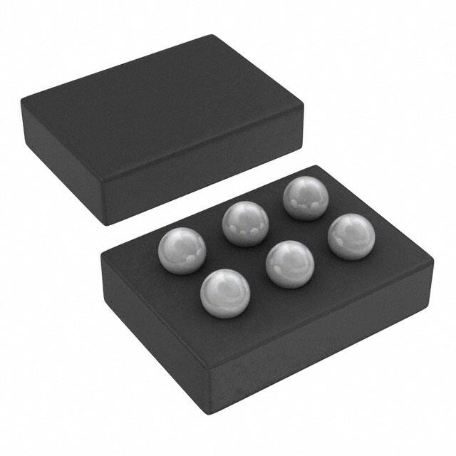
The TPS6262x devices are available in an 6-bump chip scale package (YFF, NanoFree™). The package
dimensions are given as:
• D = 1.30 ±0.03 mm
• E = 0.926 ±0.03 mm
Copyright © 2009–2015, Texas Instruments Incorporated
Submit Documentation Feedback
21
�PACKAGE OPTION ADDENDUM
www.ti.com
20-Aug-2021
PACKAGING INFORMATION
Orderable Device
Status
(1)
Package Type Package Pins Package
Drawing
Qty
Eco Plan
(2)
Lead finish/
Ball material
MSL Peak Temp
Op Temp (°C)
Device Marking
(3)
(4/5)
(6)
TPS62620YFDR
ACTIVE
DSBGA
YFD
6
3000
RoHS & Green
SNAGCU
Level-1-260C-UNLIM
-40 to 85
GE
TPS62620YFDT
ACTIVE
DSBGA
YFD
6
250
RoHS & Green
SNAGCU
Level-1-260C-UNLIM
-40 to 85
GE
TPS62620YFFR
ACTIVE
DSBGA
YFF
6
3000
RoHS & Green
SNAGCU
Level-1-260C-UNLIM
-40 to 85
GF
TPS62620YFFT
ACTIVE
DSBGA
YFF
6
250
RoHS & Green
SNAGCU
Level-1-260C-UNLIM
-40 to 85
GF
TPS62621YFFR
ACTIVE
DSBGA
YFF
6
3000
RoHS & Green
SNAGCU
Level-1-260C-UNLIM
-40 to 85
GH
TPS62621YFFT
ACTIVE
DSBGA
YFF
6
250
RoHS & Green
SNAGCU
Level-1-260C-UNLIM
-40 to 85
GH
TPS62622YFFR
ACTIVE
DSBGA
YFF
6
3000
RoHS & Green
SNAGCU
Level-1-260C-UNLIM
-40 to 85
GV
TPS62622YFFT
ACTIVE
DSBGA
YFF
6
250
RoHS & Green
SNAGCU
Level-1-260C-UNLIM
-40 to 85
GV
TPS62623YFDR
ACTIVE
DSBGA
YFD
6
3000
RoHS & Green
SNAGCU
Level-1-260C-UNLIM
-40 to 85
K3
TPS62623YFDT
ACTIVE
DSBGA
YFD
6
250
RoHS & Green
SAC396
Level-1-260C-UNLIM
-40 to 85
K3
TPS62623YFFR
ACTIVE
DSBGA
YFF
6
3000
RoHS & Green
SNAGCU
Level-1-260C-UNLIM
-40 to 85
GZ
TPS62623YFFT
ACTIVE
DSBGA
YFF
6
250
RoHS & Green
SNAGCU
Level-1-260C-UNLIM
-40 to 85
GZ
TPS62624YFFR
ACTIVE
DSBGA
YFF
6
3000
RoHS & Green
SNAGCU
Level-1-260C-UNLIM
-40 to 85
GX
TPS62624YFFT
ACTIVE
DSBGA
YFF
6
250
RoHS & Green
SNAGCU
Level-1-260C-UNLIM
-40 to 85
GX
TPS62625YFFR
ACTIVE
DSBGA
YFF
6
3000
RoHS & Green
SNAGCU
Level-1-260C-UNLIM
-40 to 85
KC
TPS62625YFFT
ACTIVE
DSBGA
YFF
6
250
RoHS & Green
SNAGCU
Level-1-260C-UNLIM
-40 to 85
KC
(1)
The marketing status values are defined as follows:
ACTIVE: Product device recommended for new designs.
LIFEBUY: TI has announced that the device will be discontinued, and a lifetime-buy period is in effect.
NRND: Not recommended for new designs. Device is in production to support existing customers, but TI does not recommend using this part in a new design.
PREVIEW: Device has been announced but is not in production. Samples may or may not be available.
OBSOLETE: TI has discontinued the production of the device.
Addendum-Page 1
Samples
�PACKAGE OPTION ADDENDUM
www.ti.com
20-Aug-2021
(2)
RoHS: TI defines "RoHS" to mean semiconductor products that are compliant with the current EU RoHS requirements for all 10 RoHS substances, including the requirement that RoHS substance
do not exceed 0.1% by weight in homogeneous materials. Where designed to be soldered at high temperatures, "RoHS" products are suitable for use in specified lead-free processes. TI may
reference these types of products as "Pb-Free".
RoHS Exempt: TI defines "RoHS Exempt" to mean products that contain lead but are compliant with EU RoHS pursuant to a specific EU RoHS exemption.
Green: TI defines "Green" to mean the content of Chlorine (Cl) and Bromine (Br) based flame retardants meet JS709B low halogen requirements of


 工商网监
湘ICP备2023018690号
工商网监
湘ICP备2023018690号
