User's Guide
SLVU877 – February 2013
4.5-V to 18-V Input, Dual 3.5-A Synchronous Step-Down
Converter With I2C Controlled VID and Current Sharing
Evaluation Module
This document is provided with the TPS65273V PMIC evaluation module (EVM) as a supplement to the
TPS65273V datasheet. This user's guide includes the schematic, hardware setup, software installation
and bill of materials (BOM).
1
2
3
4
5
6
7
Contents
Introduction .................................................................................................................. 2
Background .................................................................................................................. 2
TPS65273V Schematic ..................................................................................................... 3
Board Layout ................................................................................................................ 4
Bench Test Setup Conditions ............................................................................................. 7
5.1
Header Description and Jumper Placement .................................................................... 7
5.2
Hardware Requirement ............................................................................................ 8
5.3
Hardware Setup .................................................................................................... 8
5.4
Installing Software ................................................................................................. 9
5.5
Software Operation ............................................................................................... 10
Power-Up Procedure ...................................................................................................... 11
TPS65273V EVM Bill of Materials ....................................................................................... 12
List of Figures
1
TPS65273V Schematic..................................................................................................... 3
2
Component Placement (Top Layer) ...................................................................................... 4
3
Board Layout (Top Layer).................................................................................................. 5
4
Board Layout (Second Layer) ............................................................................................. 5
5
Board Layout (Third Layer) ................................................................................................ 6
6
Board Layout (Bottom Layer) .............................................................................................. 6
7
Header Description and Jumper Placement ............................................................................. 7
8
USB Interface Adapter Quick Connection Diagram .................................................................... 9
9
Screen Capture of TPS65273V Software GUI Interface ............................................................. 10
List of Tables
1
Summary of Performance .................................................................................................. 2
2
Input/Output Connection ................................................................................................... 7
3
Jumpers and Switches ..................................................................................................... 8
4
TPS65273V EVM Bill of Materials....................................................................................... 12
Windows, Microsoft, Internet Explorer are registered trademarks of Microsoft Corporation.
VeriSign is a trademark of VeriSign, Inc.
SLVU877 – February 2013
Submit Documentation Feedback
4.5-V to 18-V Input, Dual 3.5-A Synchronous Step-Down Converter With I2C
Controlled VID and Current Sharing Evaluation Module
Copyright © 2013, Texas Instruments Incorporated
1
�Introduction
1
www.ti.com
Introduction
This document presents the information required to operate the TPS65273V PMIC as well as the support
documentation including schematic, layout, hardware setup, software installation and bill of materials.
2
Background
The TPS65273V PMIC is designed to provide dual 3.5 A of continuous currents with an operational range
of 4.5 to 18 V. The TPS65273V features I2C controlled voltage identification (VID) and the output voltage
can be set by I2C from 0.68 V to 1.95 V. Without I2C, voltage can also be programmed by an external
resistor divider. The TPS65273V features externally programmed switching frequency ranging from 200
kHz to 1.6 MHz, external compensation, soft-start and enable.
As there are many possible options to set the converters, Table 1 presents the performance specification
summary for the EVM.
Table 1. Summary of Performance
Test Conditions
Performance
Vin = 4.5 V to 18 V
Buck1 : 1.0 V, up to 3.5 A, VID control
fsw = 500 kHz (25°C ambient)
Buck2 : 1.1 V, up to 3.5 A, VID control
The EVM is designed to provide access to the features of the TPS65273V. Some modifications can be
made to this module to test performance at different input and output voltages, current and switching
frequency. Please contact TI Field Applications Group for advice on these matters.
2
4.5-V to 18-V Input, Dual 3.5-A Synchronous Step-Down Converter With I2C
Controlled VID and Current Sharing Evaluation Module
Copyright © 2013, Texas Instruments Incorporated
SLVU877 – February 2013
Submit Documentation Feedback
�TPS65273V Schematic
www.ti.com
3
TPS65273V Schematic
Figure 1 shows the TPS65273V PMIC EVM schematic.
Figure 1. TPS65273V Schematic
SLVU877 – February 2013
Submit Documentation Feedback
4.5-V to 18-V Input, Dual 3.5-A Synchronous Step-Down Converter With I2C
Controlled VID and Current Sharing Evaluation Module
Copyright © 2013, Texas Instruments Incorporated
3
�Board Layout
4
www.ti.com
Board Layout
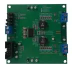
Figure 2 through Figure 6 illustrate the printed-circuit boards for this EVM.
Figure 2. Component Placement (Top Layer)
4
4.5-V to 18-V Input, Dual 3.5-A Synchronous Step-Down Converter With I2C
Controlled VID and Current Sharing Evaluation Module
Copyright © 2013, Texas Instruments Incorporated
SLVU877 – February 2013
Submit Documentation Feedback
�Board Layout
www.ti.com
Figure 3. Board Layout (Top Layer)
Figure 4. Board Layout (Second Layer)
SLVU877 – February 2013
Submit Documentation Feedback
4.5-V to 18-V Input, Dual 3.5-A Synchronous Step-Down Converter With I2C
Controlled VID and Current Sharing Evaluation Module
Copyright © 2013, Texas Instruments Incorporated
5
�Board Layout
www.ti.com
Figure 5. Board Layout (Third Layer)
Figure 6. Board Layout (Bottom Layer)
6
4.5-V to 18-V Input, Dual 3.5-A Synchronous Step-Down Converter With I2C
Controlled VID and Current Sharing Evaluation Module
Copyright © 2013, Texas Instruments Incorporated
SLVU877 – February 2013
Submit Documentation Feedback
�Bench Test Setup Conditions
www.ti.com
5
Bench Test Setup Conditions
5.1
Header Description and Jumper Placement
Figure 7 illustrates the header description and jumper placement for the EVM.
JP1/EN1
J31:
VOUT2
JP2/EN2
JP7/ADDR
JP8/MODE
B
GND
J1:5/12V
2
JP9:I C IO
POWER
A
2
JP15/I C
J18:
VOUT1
Test points:
A: LX of Vout1
B: LX of Vout2
Vout1, Vout2
Figure 7. Header Description and Jumper Placement
Table 2 shows the I/O connections for the EVM.
Table 2. Input/Output Connection
Jumper Number
Function
Description
J1
Vin Connector
Apply power supply to this connector
J18
Buck1 Connector
Output of Buck1
J31
Buck2 Connector
Output of Buck2
SLVU877 – February 2013
Submit Documentation Feedback
4.5-V to 18-V Input, Dual 3.5-A Synchronous Step-Down Converter With I2C
Controlled VID and Current Sharing Evaluation Module
Copyright © 2013, Texas Instruments Incorporated
7
�Bench Test Setup Conditions
www.ti.com
Table 3 shows the jumpers and switches for the EVM.
Table 3. Jumpers and Switches
5.2
Jumper
Number
Function
Placement
Comment
JP1
Buck1 enable (EN1)
Connect EN1 to GND to disable Vout1, connect EN1 to
Vin through a 100-kΩ resistor to enable Vout1; Leave
open to enable Vout1
JP2
Buck2 enable (EN2)
Connect EN2 to GND to disable Vout2, connect EN2 to
Vin through a 100-kΩ resistor to enable Vout2; Leave
open to enable Vout2
JP7
I2C address
I2C address configuration pin. Connect this pin to GND
to set address 0x60H; connect it to Vcc to set address
0x61H; leave it open to set address 0x62H
JP8
Mode
Operation mode control pin. Connect this pin to GND to
set forced PWM mode; leave the pin open to set auto
PSM-PWM; connect this pin to Vcc, set the IC to run in
current share mode.
JP9
I2C Power
Power connected to the I2C IO pull-up resistor; Leave
On board Vcc is 6.25 V
the two pins un-connected set the power to be 3.3V from
the I2C interface adaptor; short the two pins set the
power to be Vcc.
JP15
I2C interface connector
Pin 5 is 3.3 V from adaptor; pin 6 is Ground; pin 9 is
SCL, pin 10 is SDA.
On board Vcc is 6.25 V
Hardware Requirement
This EVM requires an external power supply capable of providing 4.5 V to 18 V at 7 A.
A function generator capable of driving the SYNC pin with 0.4- to 3.3-V amplitude and a 200-kHz to 1.6MHz square wave signal is required for synchronization. The EVM kit includes a USB-TO-GPIO interface
box which, when installed on a PC and connected to the EVM, allows communication with the EVM via a
GUI interface. The minimum PC requirements are:
• Windows® 2000 or Windows XP operating system
• USB port
• Minimum of 30 MB of free hard disk space (100 MB recommended)
• Minimum of 256 MB of RAM
5.3
Hardware Setup
After connecting the power supply to J1, turn on the power supply, and connect JP1 to Vin through a 100kΩ resistor, connect JP2 to Vin through a 100-kΩ resistor, connect JP7 to GND, connect JP8 to GND, the
EVM will regulate the output voltages to the values shown in Table 1. Additional input capacitance may be
required in order to mitigate the inductive voltage droop that may occur during a load transient event.
The output voltage is changed by sending the digital control signal via a PC running the TPS65273V
controller software and USB-TO-GPIO interface box. Change the output voltage with the following steps:
• Connect one end of the USB-TO-GPIO box to the PC using the USB cable and the other end to JP15
of the TPS65273V using the supplied 10-pin ribbon cable as shown in Figure 8. The connectors on the
ribbon cable are keyed to prevent incorrect installation.
• Connect the power supply on J1, and turn on the power supply.
• Run the software as explained in the next section.
8
4.5-V to 18-V Input, Dual 3.5-A Synchronous Step-Down Converter With I2C
Controlled VID and Current Sharing Evaluation Module
Copyright © 2013, Texas Instruments Incorporated
SLVU877 – February 2013
Submit Documentation Feedback
�Bench Test Setup Conditions
www.ti.com
Host
Computer
10-Pin
Ribbon
Cable
USB
Interface
Adapter
USB Cable
Green LED
Indicates
Power
EVM Board
Figure 8. USB Interface Adapter Quick Connection Diagram
5.4
Installing Software
If installing from the TI Web site, go to www.ti.com.
Note: This installation page is best viewed with the Microsoft® Internet Explorer® browser (It may not
work correctly with other browsers)
Click on the install button; your PC should give you a security warning and ask if you want to install this
application. Select Install to proceed. If a pre-release or Beta version is currently installed on your PC, you
must uninstall this version of the software before installing the final version.
To run the software after installation, go to Start → All programs → Texas Instruments → TPS65273V
EVM Software.
At start-up, the software first checks the firmware version of the USB-TO-GPIO adapter box. If an incorrect
firmware version is installed, the software automatically searches on the internet (if connected) for
updates. If a new update is available, the software gives notification of the update, and downloads and
installs the software. Note that after the firmware is updated the USB cable between the adapter and PC
must be disconnected and then reconnected, as instructed during the install process. The host PC
software also automatically searches on the internet (if connected) for updates. If a new update is
available, the software gives notification of the update and downloads and installs it. During future use of
the software, a prompt may be given to install a new version, if one becomes available.
NOTE:
VeriSign™ Code Signing is used to prevent any malicious code from changing this
application. If at any time in the future the binaries are modified, the code will no longer
attempt to run.
SLVU877 – February 2013
Submit Documentation Feedback
4.5-V to 18-V Input, Dual 3.5-A Synchronous Step-Down Converter With I2C
Controlled VID and Current Sharing Evaluation Module
Copyright © 2013, Texas Instruments Incorporated
9
�Bench Test Setup Conditions
5.5
www.ti.com
Software Operation
This section provides descriptions of the EVM software.
The supplied software is used to communicate with the TPS65273V EVM. Click on the icon on the host
computer to start the software. The software displays the main control panel for the user interface
(Figure 9).
Check “Shutdown” box to shutdown
Buck 1 or Buck 2
Check “VID Enable” box to set to output
voltage by VID
Output Voltage Selection Pulldown Boxes
Mode Selection option
Change Vout transition slew rate
Internal Register Values, can be
altered bit by bit if desired. Updates register
when “Write” button is pushed.
Figure 9. Screen Capture of TPS65273V Software GUI Interface
Figure 9 shows the GUI control interface. There are five 8-bit registers embedded in TPS65273V, two to
select the output voltage, two to configure the buck converter’s operation, and one for status feedback.
Changes are made by selecting and checking the components in the GUI on the left hand side and can
also be made by directly clicking the bits of each register. I2C address is set to default 0x60H, this address
is corresponding to the EVM jumper JP7 to connect to GND. Changing the I2C address requires that the
EVM be configured accordingly.
An option is to “write on change”, if this option is set to ON, any change is sent to the EVM immediately; if
this option is set to OFF, “Write” button or “W” button for each register must be clicked to send the control
signal.
Register values can be read back from the EVM by clicking “Read” or “R” for each register.
10
4.5-V to 18-V Input, Dual 3.5-A Synchronous Step-Down Converter With I2C
Controlled VID and Current Sharing Evaluation Module
Copyright © 2013, Texas Instruments Incorporated
SLVU877 – February 2013
Submit Documentation Feedback
�Power-Up Procedure
www.ti.com
6
Power-Up Procedure
Use the following steps to power-up the EVM:
1. Connect I2C adaptor to JP15
2. Apply 4.5 V to J1
3. Toggle JP1 or JP2 to enable Vout1 and Vout2, respectively
4. Apply loads to the output connectors.
SLVU877 – February 2013
Submit Documentation Feedback
4.5-V to 18-V Input, Dual 3.5-A Synchronous Step-Down Converter With I2C
Controlled VID and Current Sharing Evaluation Module
Copyright © 2013, Texas Instruments Incorporated
11
�TPS65273V EVM Bill of Materials
7
www.ti.com
TPS65273V EVM Bill of Materials
Table 4 is the BOM for the EVM.
Table 4. TPS65273V EVM Bill of Materials
#
Value
Qty
Designator
Footprint
MFG
1
10nF
2
C1, C2
0603
Generic
2
10nF
4
C22, C23, C26, C27
0603
Generic
3
10uF
2
C5, C11
1210
Panasonic -ECG
ECJ-4YB1E106M
CAP 10UF 25V CERAMIC X5R 1210
4
10uF
1
C9
0603
Panasonic -ECG
ECJ-1VB1A106M
CAP 10UF 10V CERAMIC X5R 0603
5
1uF
1
C15
0603
Generic
CAP 1UF 10V CERAMIC X5R 0603
6
82pF
2
C18, C31
0603
Generic
CAP 82pF 50V CERAMIC X7R 0603
7
47nF
2
C19, C30
0603
Generic
8
22uF
12
C20, C28, C201, C202, C203, C204, C205,
C281, C282, C283, C284, C285
0805
TDK
C2012X6S0J226M
CAP CER 22UF 6.3V 20% X6S 0805
9 (1)
470uF
DNI
C204, C284
E_CAP_D8_L6.7
Nichicon
RHA0J471MCN1GS
CAP ALUM 470UF 6.3V 20% SMD
10
47pF
DNI
C231, C261
0603
Generic
11 (1)
ED500/2DS
3
J1, J18, J31
TB_2X5.0MM
OnShore Technology Inc
ED500/2DS
Terminal Block, 2-pin, 15-A, 5.0mm
12
HEADER 3 PIN
4
JP1, JP2, JP7, JP8
JMP0.3
Mil-Max
800-10-064-10-001000
Three Pin Header
13
HEADER 2 PIN (2)
1
JP9
JMP0.2
Mil-Max
800-10-064-10-001000
Two Pin Header
14
HEADER 10 PIN (3)
1
JP15,
HEADER10
3M
N2510-6002-RB
Ten Pin Header
15
3.3uH
2
L1, L2
IND3
Coilcraft
MSS1048-332NLB
SMT power inductor
16
100K
2
R1, R2
0603
Generic
RES 100k OHM 1/10W 1% 0603 SMD
17
100K
1
R24
0603
Generic
RES 100k OHM 1/10W 1% 0603 SMD
18
10k
2
R15, R16
0603
Generic
RES 10k OHM 1/10W 1% 0603 SMD
19
60.4K
1
R17
0603
Generic
RES 60.4k OHM 1/10W 1% 0603 SMD
20
40.2K
2
R18, R31
0603
Generic
RES 40.2k OHM 1/10W 1% 0603 SMD
21
0
6
R19, R30, R181, R182, R311, R312
0603
Generic
RES 0 OHM 1/10W 1% 0603 SMD
22
3.74k
2
R23, R26
0603
Generic
RES 3.7k OHM 1/10W 1% =0603 SMD
23
48.7k
1
R32
0603
Generic
24
Test Point White
11
TP1, TP2, TP5, TP15, TP16, TP17, TP18,
TP24, TP31, TP32, TP151
TP
Keystone
5002
TEST POINT PC MINI .040"D WHITE
25
Test Point Black
4
TP10, TP12, TP13, TP14
TP
Keystone
5001
TEST POINT PC MINI .040"D BLACK
3M
SJ-5303 (CLEAR)
Texas Instruments
TPS65273V
26 (4)
4
27 (5)
4
28
1
(1)
(2)
(3)
(4)
(5)
12
MFG Part Number
Description
CAP 10nF 50V CERAMIC X7R 0603
CAP 10nF 50V CERAMIC X7R 0603
CAP 47nF 50V CERAMIC X7R 0603
CAP 47pF 50V CERAMIC X7R 0603
RES 48.7k OHM 1/10W 1% 0603 SMD
Jumper, 2.54mm, applied on item 13
U1
BUMPON HEMISPHERE .44X.20 CLEAR
Item 9, 11: optional
Item 13: split into 3 pins
Item 14: split into 2 pins
Install item 26 on item 13 no order - be consistent
Install item 27 on bottom at corners
4.5-V to 18-V Input, Dual 3.5-A Synchronous Step-Down Converter With I2C
Controlled VID and Current Sharing Evaluation Module
Copyright © 2013, Texas Instruments Incorporated
SLVU877 – February 2013
Submit Documentation Feedback
�IMPORTANT NOTICE
Texas Instruments Incorporated and its subsidiaries (TI) reserve the right to make corrections, enhancements, improvements and other
changes to its semiconductor products and services per JESD46, latest issue, and to discontinue any product or service per JESD48, latest
issue. Buyers should obtain the latest relevant information before placing orders and should verify that such information is current and
complete. All semiconductor products (also referred to herein as “components”) are sold subject to TI’s terms and conditions of sale
supplied at the time of order acknowledgment.
TI warrants performance of its components to the specifications applicable at the time of sale, in accordance with the warranty in TI’s terms
and conditions of sale of semiconductor products. Testing and other quality control techniques are used to the extent TI deems necessary
to support this warranty. Except where mandated by applicable law, testing of all parameters of each component is not necessarily
performed.
TI assumes no liability for applications assistance or the design of Buyers’ products. Buyers are responsible for their products and
applications using TI components. To minimize the risks associated with Buyers’ products and applications, Buyers should provide
adequate design and operating safeguards.
TI does not warrant or represent that any license, either express or implied, is granted under any patent right, copyright, mask work right, or
other intellectual property right relating to any combination, machine, or process in which TI components or services are used. Information
published by TI regarding third-party products or services does not constitute a license to use such products or services or a warranty or
endorsement thereof. Use of such information may require a license from a third party under the patents or other intellectual property of the
third party, or a license from TI under the patents or other intellectual property of TI.
Reproduction of significant portions of TI information in TI data books or data sheets is permissible only if reproduction is without alteration
and is accompanied by all associated warranties, conditions, limitations, and notices. TI is not responsible or liable for such altered
documentation. Information of third parties may be subject to additional restrictions.
Resale of TI components or services with statements different from or beyond the parameters stated by TI for that component or service
voids all express and any implied warranties for the associated TI component or service and is an unfair and deceptive business practice.
TI is not responsible or liable for any such statements.
Buyer acknowledges and agrees that it is solely responsible for compliance with all legal, regulatory and safety-related requirements
concerning its products, and any use of TI components in its applications, notwithstanding any applications-related information or support
that may be provided by TI. Buyer represents and agrees that it has all the necessary expertise to create and implement safeguards which
anticipate dangerous consequences of failures, monitor failures and their consequences, lessen the likelihood of failures that might cause
harm and take appropriate remedial actions. Buyer will fully indemnify TI and its representatives against any damages arising out of the use
of any TI components in safety-critical applications.
In some cases, TI components may be promoted specifically to facilitate safety-related applications. With such components, TI’s goal is to
help enable customers to design and create their own end-product solutions that meet applicable functional safety standards and
requirements. Nonetheless, such components are subject to these terms.
No TI components are authorized for use in FDA Class III (or similar life-critical medical equipment) unless authorized officers of the parties
have executed a special agreement specifically governing such use.
Only those TI components which TI has specifically designated as military grade or “enhanced plastic” are designed and intended for use in
military/aerospace applications or environments. Buyer acknowledges and agrees that any military or aerospace use of TI components
which have not been so designated is solely at the Buyer's risk, and that Buyer is solely responsible for compliance with all legal and
regulatory requirements in connection with such use.
TI has specifically designated certain components as meeting ISO/TS16949 requirements, mainly for automotive use. In any case of use of
non-designated products, TI will not be responsible for any failure to meet ISO/TS16949.
Products
Applications
Audio
www.ti.com/audio
Automotive and Transportation
www.ti.com/automotive
Amplifiers
amplifier.ti.com
Communications and Telecom
www.ti.com/communications
Data Converters
dataconverter.ti.com
Computers and Peripherals
www.ti.com/computers
DLP® Products
www.dlp.com
Consumer Electronics
www.ti.com/consumer-apps
DSP
dsp.ti.com
Energy and Lighting
www.ti.com/energy
Clocks and Timers
www.ti.com/clocks
Industrial
www.ti.com/industrial
Interface
interface.ti.com
Medical
www.ti.com/medical
Logic
logic.ti.com
Security
www.ti.com/security
Power Mgmt
power.ti.com
Space, Avionics and Defense
www.ti.com/space-avionics-defense
Microcontrollers
microcontroller.ti.com
Video and Imaging
www.ti.com/video
RFID
www.ti-rfid.com
OMAP Applications Processors
www.ti.com/omap
TI E2E Community
e2e.ti.com
Wireless Connectivity
www.ti.com/wirelessconnectivity
Mailing Address: Texas Instruments, Post Office Box 655303, Dallas, Texas 75265
Copyright © 2013, Texas Instruments Incorporated
�


 工商网监
湘ICP备2023018690号
工商网监
湘ICP备2023018690号
