User's Guide
SCDU003B – March 2013 – Revised August 2013
TS3A226AE Evaluation Board
This user guide describes the TS3A226AE evaluation module (EVM) usage. This guide contains the EVM
schematics, evaluation examples, and bill of materials to evaluate the performance of the TS3A226AE
device.
1
2
3
4
5
Contents
Introduction ..................................................................................................................
EVM Setuup .................................................................................................................
2.1
Boards ...............................................................................................................
2.2
Setup Procedure ...................................................................................................
Evaluating TS3A226AE ....................................................................................................
3.1
Test with Different Types of Headsets ..........................................................................
EVM Schematics ............................................................................................................
Bill of Materials ..............................................................................................................
1
2
2
2
3
3
4
5
List of Figures
1
TS3A226AE Evaluation board
............................................................................................
2
2
TS3A226AE EVM Schematic..............................................................................................
4
List of Tables
1
1
TS3A226AE Evaluation Module Signal Connections
..................................................................
2
2
Bill of Materials ..............................................................................................................
5
Introduction
The TS3A226AE is an audio headset switch that detects 3- or 4-pole 3.5mm accessories. For a 4-pole
accessory with a microphone, the TS3A226AE also detects the MIC location and routes the microphone
and ground signals automatically. The ground signal is routed through a pair of low-impedance ground
FETs (60mΩ typical), resulting minimal impact on audio cross-talk performance. The autonomous
detection feature allows end users to plug in accessories with different audio pole configurations into the
mobile device and have them operate properly with no added software control and complexity. The ground
FETs of the device are designed to allow FM signal pass-through, making it possible to use the ground
line of the headset as an FM antenna in mobile audio application.
The TS3A226AE EVM is an evaluation module for the Texas Instruments TS3A226AE switch and it
provides the basic functionality evaluation for the device.
SCDU003B – March 2013 – Revised August 2013
Submit Documentation Feedback
TS3A226AE Evaluation Board
Copyright © 2013, Texas Instruments Incorporated
1
�EVM Setuup
2
EVM Setuup
2.1
Boards
www.ti.com
One TS3A226AE Evaluation board is provided per EVM kit:
Figure 1. TS3A226AE Evaluation board
Table 1. TS3A226AE Evaluation Module Signal Connections
Type
Description
Purpose
J3
SMA Connector
FM signal output
If GND is used for FM signal transmission, FM receiver can be connected to this connector
for sensitivity test.
J4
RCA Connector
For MIC signal output
Can be connected to Codec for microphone testing.
J5
RCA Connector
RING1 connection
Can be connected to Audio Amplifier (right channel) output for audio testing.
J6
RCA Connector
TIP connection
Can be connected to Audio Amplifier (left channel) output for audio testing.
J7
Audio Jack Connector Audio Jack for Headset plug in
Plug in different Headset for TS3A226AE function verification
Test Point headers are placed throughout the board to provide testing capability for each pin of the device
and are labeled with the corresponding pin name beside the header pins.
2.2
Setup Procedure
2.2.1
•
•
2.2.2
Equipment Required
Power supply which can provide 2.6V to 4.7V
Multi-meter
Power up
To provide the VDD to the TS3A226AE. Add the jumper for J1 and J2.
2
TS3A226AE Evaluation Board
SCDU003B – March 2013 – Revised August 2013
Submit Documentation Feedback
Copyright © 2013, Texas Instruments Incorporated
�Evaluating TS3A226AE
www.ti.com
External power supply input are supplied to the VDD test point (TP6) for VDD and GND test points (TP12)
for GND.
3
Evaluating TS3A226AE
3.1
Test with Different Types of Headsets
To evaluate the capability of headset detection for TS3A226AE, plug in different types of headsets (4-pole
standard, 4-pole OMTP, or regular TRS) to the headset jack J7, and check the detection result.
(1) 4-Pole Standard/ North American Headsets:
L
R
G
M
If a 4-pole standard/North American headset is plugged-in, below table can be used to check the detection
result by measuring the resistor through the hand multi-meter.
TEST POINTS
Negative Pole
Positive Pole
Measured Value(Ω)
TP13(MICP)
TP15(SLEEVE)
≤10
TP13(MICP)
TP16(RING2)
>1K
TP21(GNDA)
TP15(SLEEVE)
>1K
TP12(GNDB)
TP16(RING2)
≤2
(2) 4-Pole OMTP Headsets:
L
R
M G
If a 4-pole OMTP headset is plugged-in, below table can be used to check the detection result by
measuring the resistor through the hand multi-meter.
TEST POINTS
Negative Pole
Positive Pole
Measured Value(Ω)
TP13(MICP)
TP15(SLEEVE)
>1K
TP13(MICP)
TP16(RING2)
≤10
TP21(GNDA)
TP15(SLEEVE)
≤2
TP12(GNDB)
TP16(RING2)
>1K
(3) RS Audio Headset:
L
R
G
If a regular TRS headset without integrated microphone is plugged-in, below table can be used to check
the detection result by measuring the resistor through the hand multi-meter.
TEST POINTS
Negative Pole
Positive Pole
Measured Value(Ω)
TP13(MICP)
TP15(SLEEVE)
很抱歉,暂时无法提供与“TS3A226AEEVM”相匹配的价格&库存,您可以联系我们找货
免费人工找货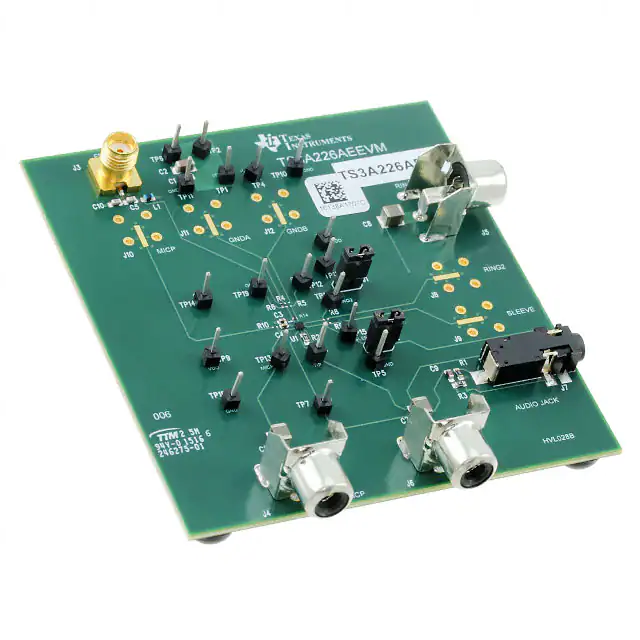


 工商网监
湘ICP备2023018690号
工商网监
湘ICP备2023018690号

