Document 528-1
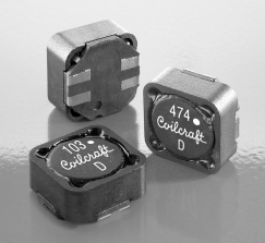
Shielded Coupled Inductors MSD1260
• Tight coupling (k ≥ 0.98)
• 500 Vrms, one minute isolation (hipot) between windings
• Ideal for use in a variety of circuits including flyback, multi-output
buck, SEPIC and Zeta.
• High inductance, high efficiency and excellent current handling
• Can also be used as two single inductors connected in series
or parallel, as a common mode choke or as a 1 : 1 transformer.
+
+
D
L1
C
L2
VOUT
C
VIN
–
SW
–
Typical Flyback Converter
D
L2
+
VOUT
C
AUX
–
0.484
max
12,3
0.484
max
12,3
123
X
+
+
VIN
Dot indicates pin1
L1
D
SW
–
Dash number
–
Typical Buck Converter with auxiliary output
Internal code
D
+
L1
0.236 ±0.008*
6,0 ±0,2
Recommended
Land Pattern
0.197
5,0
VIN
C
–
0.157
4,0
L2
C
4
2
2
1
3
+
1
0.177
4,5
4
–
0.079
2,0
L2
C1
Q
VIN
VOUT
–
Typical SEPIC schematic
+
3
0.059
1,5
+
C1
Q
0.217
5,5
0.197
5,0
0.138
3,5
VOUT
C
L1
C
D
Typical Zeta schematic
C
VOUT
–
* For optional tin-lead and tin-silver-copper
terminations, dimensions are for the mounted
part. Dimensions before mounting can be
an additional 0.012 inch (0,3 mm).
Dimensions are in
inches
mm
1
L1
3
2
L2
4
US +1-847-639-6400 sales@coilcraft.com
UK +44-1236-730595 sales@coilcraft-europe.com
Taiwan +886-2-2264 3646 sales@coilcraft.com.tw
China +86-21-6218 8074 sales@coilcraft.com.cn
Singapore + 65-6484 8412 sales@coilcraft.com.sg
Document 528-1 Revised 11/09/15
© Coilcraft Inc. 2017
This product may not be used in medical or high
risk applications without prior Coilcraft approval.
Specification subject to change without notice.
Please check web site for latest information.
�Document 528-2
Shielded Coupled Inductors – MSD1260 Series
Irms (A)
Coupling Leakage
Inductance2
DCR max3
SRF typ4 coefficient
Inductance5
Isat6 both one
windings7 winding8
Part number1
(µH)
(Ohms)
(MHz)
typ
typ (µH)
(A)
MSD1260-472ML_ 4.7 ±20%
MSD1260-562ML_ 5.6 ±20%
MSD1260-682ML_ 6.8 ±20%
MSD1260-822ML_ 8.2 ±20%
MSD1260-103ML_ 10 ±20%
0.036
0.040
0.048
0.052
0.060
32.0
31.0
28.0
25.0
22.0
0.98
0.98
0.98
0.98
0.99
0.20
0.20
0.24
0.25
0.26
10.3
9.66
9.21
8.55
7.40
3.16
3.00
2.75
2.63
2.45
4.47
4.24
3.88
3.72
3.46
MSD1260-123ML_ 12 ±20%
MSD1260-153ML_ 15 ±20%
MSD1260-183ML_ 18 ±20%
MSD1260-223ML_ 22 ±20%
MSD1260-273ML_ 27 ±20%
0.074
0.085
0.097
0.116
0.124
21.0
17.6
17.0
15.0
13.6
0.99
0.99
0.99
0.98
0.99
0.28
0.32
0.40
0.68
0.50
6.86
6.09
5.30
5.01
4.66
2.21
2.06
1.93
1.76
1.70
3.12
2.92
2.73
2.49
2.41
MSD1260-333ML_ 33 ±20%
MSD1260-393ML_ 39 ±20%
MSD1260-473ML_ 47 ±20%
MSD1260-563ML_ 56 ±20%
MSD1260-683ML_ 68 ±20%
0.134
0.142
0.174
0.198
0.216
12.7
11.7
8.7
7.6
6.1
0.99
0.99
0.99
0.99
>0.99
0.65
1.09
0.80
0.75
0.57
4.22
3.80
3.25
3.07
2.83
1.64
1.59
1.44
1.35
1.29
2.32
2.25
2.03
1.91
1.83
MSD1260-823ML_ 82 ±20%
MSD1260-104ML_ 100 ±20%
MSD1260-124KL_ 120 ±10%
MSD1260-154KL_ 150 ±10%
MSD1260-184KL_ 180 ±10%
0.274
0.322
0.418
0.476
0.536
5.3
5.0
4.4
4.0
3.6
0.99
0.99
0.99
0.99
0.99
1.52
1.41
1.34
1.52
1.80
2.55
2.20
2.05
1.82
1.60
1.15
1.06
0.93
0.87
0.82
1.62
1.50
1.31
1.23
1.16
MSD1260-224KL_
MSD1260-274KL_
MSD1260-334KL_
MSD1260-394KL_
MSD1260-474KL_
0.691
0.806
1.09
1.20
1.59
3.2
2.8
2.5
2.3
2.1
>0.99
>0.99
>0.99
>0.99
>0.99
1.60
2.23
2.39
3.72
2.89
1.51
1.41
1.28
1.16
1.00
0.72
0.67
0.57
0.55
0.48
1.02
0.95
0.81
0.77
0.67
1.81
2.06
2.65
3.06
2.0
1.8
1.5
1.2
>0.99
>0.99
>0.99
>0.99
2.55
5.76
2.86
4.32
0.95
0.88
0.79
0.69
0.45
0.42
0.37
0.34
0.63
0.59
0.52
0.49
220 ±10%
270 ±10%
330 ±10%
390 ±10%
470 ±10%
MSD1260-564KL_ 560 ±10%
MSD1260-684KL_ 680 ±10%
MSD1260-824KL_ 820 ±10%
MSD1260-105KL_
1000 ±10%
1. When ordering, please specify termination and packaging codes:
MSD1260-105KLD
Termination: L = RoHS compliant matte tin over nickel over phos
bronze.
Special order: T = RoHS tin-silver-copper (95.5/4/0.5) or
S = non-RoHS tin-lead (63/37).
Packaging: D
= 13″ machine-ready reel. EIA-481 embossed plastic
tape (500 parts per full reel).
B = Less than full reel. In tape, but not machine ready.
To have a leader and trailer added ($25 charge), use
code letter D instead.
2. Inductance shown for each winding, measured at 100 kHz, 0.1 Vrms,
0 Adc on an Agilent/HP 4284A LCR meter or equivalent. When leads
are connected in parallel, inductance is the same value. When leads are
connected in series, inductance is four times the value.
3. DCR is for each winding. When leads are connected in parallel, DCR
is half the value. When leads are connected in series, DCR is twice the
value.
4. SRF measured using an Agilent/HP 4191A or equivalent. When leads
are connected in parallel, SRF is the same value.
5. Leakage Inductance is for L1 and is measured with L2 shorted.
6. DC current, at which the inductance drops 30% (typ) from its value
without current. It is the sum of the current flowing in both windings.
7. Equal current when applied to each winding simultaneously that causes
a 40°C temperature rise from 25°C ambient. This information is for reference only and does not represent absolute maximum ratings. To predict
temperature rise go to online calculator.
8. Maximum current when applied to one winding that causes a 40°C temperature rise from 25°C ambient. This information is for reference only
and does not represent absolute maximum ratings. To predict temperature rise go to online calculator.
9. Electrical specifications at 25°C.
Refer to Doc 639 “Selecting Coupled Inductors for SEPIC Applications.”
Refer to Doc 362 “Soldering Surface Mount Components” before soldering.
Coupled Inductor Core and Winding Loss Calculator
This web-based utility allows you to enter frequency, peak-to-peak
(ripple) current, and Irms current to predict temperature rise and overall
losses, including core loss. Go to online calculator.
US +1-847-639-6400 sales@coilcraft.com
UK +44-1236-730595 sales@coilcraft-europe.com
Taiwan +886-2-2264 3646 sales@coilcraft.com.tw
China +86-21-6218 8074 sales@coilcraft.com.cn
Singapore + 65-6484 8412 sales@coilcraft.com.sg
Document 528-2 Revised 11/09/15
© Coilcraft Inc. 2017
This product may not be used in medical or high
risk applications without prior Coilcraft approval.
Specification subject to change without notice.
Please check web site for latest information.
�Document 528-3
Shielded Coupled Inductors – MSD1260 Series
Typical L vs Current
Typical L vs Frequency
10000
10000
-105
-474
-104
100
-473
-103
10
-105
1000
Inductance (µH)
Inductance (µH)
1000
-474
-104
100
-473
-103
10
-472
1
0.1
1
-472
10
100
Current (A)
1
0.01
0.1
1
10
Frequency (MHz)
Core material Ferrite
Core and winding loss Go to online calculator
Terminations RoHS compliant matte tin over nickel over phos bronze.
Other terminations available at additional cost.
Weight: 2.8 – 3.2 g
Ambient temperature –40°C to +85°C with (40°C rise) Irms current.
Maximum part temperature +125°C (ambient + temp rise).
Storage temperature Component: –40°C to +125°C.
Tape and reel packaging: –40°C to +80°C
Winding-to-winding isolation 500 Vrms, one minute
Resistance to soldering heat Max three 40 second reflows at
+260°C, parts cooled to room temperature between cycles
Moisture Sensitivity Level (MSL) 1 (unlimited floor life at
很抱歉,暂时无法提供与“MSD1260-103MLB”相匹配的价格&库存,您可以联系我们找货
免费人工找货- 国内价格
- 1+19.44402
- 10+18.72387
- 100+16.56343
- 500+16.13134


 工商网监
湘ICP备2023018690号
工商网监
湘ICP备2023018690号
