Available at Digi-Key
www.digikey.com
2111 Comprehensive Drive
Aurora, Illinois 60505
Phone: 630- 851- 4722
Fax: 630- 851- 5040
www.conwin.com
D
A
T
A
S
H
E
E
T
Bulletin
Page
Revision
Date
SG170
1 of 20
04
29 Nov 2011
125 Series Wi125
GPS Receiver
�TABLE OF CONTENTS
1
INTRODUCTION------------------------------------------------------------------------ 4
2
SPECIFICATION----------------------------------------------------------------------5-6
2.1
2.2
2.3
2.4
Performance --------------------------------------------------------------------------------------------5
Recommended Ratings------------------------------------------------------------------------------6
Absolute Maximum Ratings-------------------------------------------------------------------------6
Block Diagram------------------------------------------------------------------------------------------6
3
PHYSICAL CHARACTERISTICS----------------------------------------------------7-8
3.1
3.2
3.3
Physical Interface Details----------------------------------------------------------------------------7
Wi125 Dimensions-------------------------------------------------------------------------------------8
Solder Pad Size and Placement-------------------------------------------------------------------8
4
SIGNAL DESCRIPTION------------------------------------------------------------ 9-14
4.1
4.2
4.3
4.4
4.5
Power Signals-------------------------------------------------------------------------------------------9
RF Signals--------------------------------------------------------------------------------------------- 10
Emulation/Test Signals----------------------------------------------------------------------------- 10
Control Signals--------------------------------------------------------------------------------------- 11
I/O Signals--------------------------------------------------------------------------------------------- 12
5
SPECIAL FEATURES------------------------------------------------------------------14
5.1
5.2
5.3
User Commands------------------------------------------------------------------------------------- 14
Self-Survey ------------------------------------------------------------------------------------------- 14
Wi125 Embedded Identification------------------------------------------------------------------ 14
6
TAPE AND REEL SPECIFICATIONS-------------------------------------------------15
7
SOLDER PROFILE--------------------------------------------------------------------15
8
APPLICATION HINTS-------------------------------------------------------------16-17
8.1
8.2
8.3
8.4
Power Supply----------------------------------------------------------------------------------------- 16
RF Connection---------------------------------------------------------------------------------------- 16
Grounding---------------------------------------------------------------------------------------------- 17
Battery Backup--------------------------------------------------------------------------------------- 17
ORDERING INFORMATION----------------------------------------------------------18
Wi125 Data Sheet #: SG170
Page 2 of 20
Rev: 04
Date: 11/29/11
© Copyright 2011 The Connor-Winfield Corp. All Rights Reserved Specifications subject to change without notice
�Figure and Table Contents
List of Figures
Figure 1 Wi125 Block Diagram---------------------------------------------------------------------------------------7
Figure 2 Wi125 Form and Size---------------------------------------------------------------------------------------8
Figure 3 Wi125 Dimensions-------------------------------------------------------------------------------------------9
Figure 4 Solder Pad Size and Placement------------------------------------------------------------------------ 10
Figure 5 RF Tracking Example-------------------------------------------------------------------------------------- 17
Figure 6 Grounding the Wi125 with a ground plane----------------------------------------------------------- 18
Figure 7 Typical VBATT Supplies---------------------------------------------------------------------------------- 19
List of Tables
Table 1 Revision History------------------------------------------------------------------------------------------------2
Table 2 Additional Documentation List------------------------------------------------------------------------------3
Table 3 Wi125 Specification--------------------------------------------------------------------------------------------6
Table 4 Absolute Maximum Ratings---------------------------------------------------------------------------------7
Table 5 Absolute Maximum Ratings---------------------------------------------------------------------------------7
Table 6 Wi125 Signal List----------------------------------------------------------------------------------------------8
Table 7 RF Track & Gap Widths------------------------------------------------------------------------------------ 17
Revision History of Version 1.0
Revision
00
Date
07/20/09
Released By
Note
Keith Loiselle
New Release of Wi125 Data Sheet
01
04/13/10
Dave Jahr
Update to 1PPS (timing) Accuracy Specification
02
06/16/10
Dave Jahr
125 Series Revised
03
10/20/11
Dave Jahr
Update to 1PPS (timing) Accuracy Specification
04
11/29/11
Dave Jahr
RoHS Compliant Update
Table 1 Revision History
Other Documentation
The following additional documentation may be of use in understanding this document.
Document
Wi125 User Manual
By
Connor-Winfield
Note
Wi125 Dev Kit User Manual Connor-Winfield
Table 2 Additional Documentation List
Wi125 Data Sheet #: SG170
Page 3 of 20
© Copyright 2011 The Connor-Winfield Corp.
Rev: 04
Date: 11/29/11
All Rights Reserved Specifications subject to change without notice
�1 INTRODUCTION
The 125 Series Wi125 is a small OEM surface mount GPS module specifically designed for
use in synchronization and timing in WiMax applications. This compact module has an onboard programmable NCO oscillator that outputs a synthesized frequency up to 30 MHz that
is steered by a GPS receiver. The self-survey mode of operation allows the receiver to enter
a position hold mode allowing accurate timing to be continued with only one satellite being
tracked.
Additionally, the 125 Series Wi125 has phase alignment of 1 PPS/10 MHz with a very stable
holdover. The 1 PPS/10 MHz outputs maintain phase alignment with holdover being base only
on the local oscillator, dismissing spurious GPS measurements during reacquisition. When the
receiver regains GPS lock after a period of holdover, the 1PPS and 10 MHz outputs maintain
phase alignment and are offset in frequency at the maximum rate of 100 ppb until the 1 PPS
aligns with that of the GPS solution. This slow recovery from holdover allows for uninterrupted
operation of the WiMax base station.
The Wi125 has a highly accurate output frequency, which can achieve full PRC MTIE
performance. Additionally it can track satellites and provide GPS synchronization in weak
signal areas including indoor applications, reducing the need for high antenna placement.
The Wi125 is RoHS compliant and an exceptionally small surface mount package with a
highly integrated architecture that requires a minimum of external components allowing easy
integration into host systems.
Key information includes:
• System Block Diagram
• Maximum Ratings
• Physical Characteristics
Wi125 Dimensions, castellation information
Solder Pad and placement information
• Signal Descriptions
• Special Features
• Application Information
Power supply modes
RF connections
Grounding
Battery Back-up
Over Voltage and Reverse Polarity
LED’s
Features
• 1PPS/ 10 MHz Phase alignment
• Stable Holdover
• Holdover Recovery
• 1 PPS & NCO Frequency Output
• GPS/UTC time/scale synchronization
to 25 ns RMS
• Stable proven design with long term
availability and multi-year support
• 12 channel hardware correlator
processor design
• OEM SM footprint 25 x 27 mm
• Automatic entry into holdover
• Loss-of-lock and entry-into-holdover
indication
• RoHS Compliant
The specifications in the following sections refer to the standard software builds of the Wi125 . The performance
and specification of the Wi125 can be modified with the use of customized software builds.
Wi125 Data Sheet #: SG170
Page 4 of 20
Rev: 04
Date: 11/29/11
© Copyright 2011 The Connor-Winfield Corp. All Rights Reserved Specifications subject to change without notice
�2 SPECIFICATION 1
2.1 Performance
Physical
Module dimensions
Supply voltages
Operating Temp
Storage Temp
Humidity
Max Velocity / Altitude
Max Acceleration / Jerk
25mm (D) x 27mm (W) x 4.2mm (H)
3V3 (Digital I/O), 3V3 (RF), 1V8 (Core option), 3V
(Standby Battery)
-30°C to +85°C
-40°C to +85°C 2
5% to 95% non-condensing
515ms-1 / 18,000m
4g / 1gs-1 (sustained for less than 5 seconds)
Sensitivity
Acquisition w/network assist
Tracking
Acquisition Stand Alone
-185dBW
-186dBW
-173dBW
Acquisition
Time
Hot Start with network assist
Stand Alone (Outdoor)
Outdoor:
很抱歉,暂时无法提供与“WI125”相匹配的价格&库存,您可以联系我们找货
免费人工找货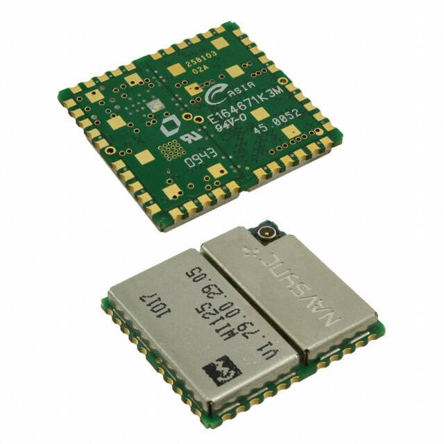


 工商网监
湘ICP备2023018690号
工商网监
湘ICP备2023018690号
