Additional Resources:
Product Page
date
08/30/2021
page
1 of 7
SERIES: PQA30-T Ϳ DESCRIPTION: DC-DC CONVERTER
FEATURES
input
voltage
NU
MODEL
ED
up to 30 W isolated output
2:1 input range (18~36 Vdc, 36~75 Vdc)
smaller package
single, regulated output
1,500 Vdc isolation
short circuit, over current, and over voltage protections
inverse polarity protection
remote on/off
operating temperature range (-40~85°C)
six sided metal shielding
efficiency up to 87%
EN 62368-1
output
voltage
W\S
(Vdc)
range
(Vdc)
PQA30-D24-S3-T
24
18~36
PQA30-D24-S5-T
24
18~36
output
current
output
power
ripple
and noise1
HϒFLHQF\
min
(A)
max
(A)
max
(W)
max
(mVp-p)
W\S
(%)
3.3
0.60
6
20
120
85
5
0.60
6
30
120
86
9
0.333
3.333
30
120
86
12
0.25
2.5
30
120
86
(Vdc)
TI
•
•
•
•
•
•
•
•
•
•
•
•
24
18~36
24
18~36
PQA30-D24-S15-T
24
18~36
15
0.20
2
30
120
87
PQA30-D24-S24-T
24
18~36
24
0.125
1.25
30
120
87
PQA30-D48-S3-T
48
36~75
3.3
0.60
6
20
120
85
PQA30-D48-S5-T
48
36~75
5
0.60
6
30
120
86
PQA30-D48-S12-T
48
36~75
12
0.25
2.5
30
120
87
PQA30-D48-S15-T
48
36~75
15
0.20
2
30
120
87
PQA30-D48-S24-T
48
36~75
24
0.125
1.25
30
120
86
SC
ON
PQA30-D24-S9-T
PQA30-D24-S12-T
Notes:
1. Ripple and noise are measured at 20 MHz BW by “parallel cable” method with 1 µF ceramic and 10 µF electrolytic capacitors on the output.
DI
PART NUMBER KEY
Notes:
PQA30 - DXX - SXX - TX
Base Number
Input Voltage
Output Voltage
*Discontinued heatsink versions.
cui.com
Mounting Type
T = Chassis Mount
Heatsink*
"blank" = no heatsink
H = with heatsink
�Additional Resources:
Product Page
CUI Inc Ϳ SERIES: PQA30-T Ϳ DESCRIPTION: DC-DC CONVERTER
date 08/30/2021 Ϳ page 2 of 7
INPUT
conditions/description
operating input voltage
24 Vdc input models
48 Vdc input models
start-up voltage
24 Vdc input models
48 Vdc input models
under voltage shutdown
24 Vdc input models
48 Vdc input models
surge voltage
for maximum of 1 second
24 Vdc input models
48 Vdc input models
start-up time
nominal input, constant load
min
W\S
max
units
18
36
24
48
36
75
Vdc
Vdc
17.8
35.8
18
36
Vdc
Vdc
16
32
Vdc
Vdc
ED
parameter
-0.7
-0.7
50
100
Vdc
Vdc
10
ms
1
mA
models ON (CTRL open or connect TTL high level, 2.5~12 Vdc)
models OFF (CTRL connect GND or low level, 0~1.2 Vdc)
¿OWHU
SL�¿OWHU
input current (models OFF)
Note
1. CTRL pin voltage is referenced to GND.
OUTPUT
conditions/description
line regulation
load regulation
W\S
max
units
full load, input voltage from low to high
±0.2
±0.5
%
10% to 100% load
±0.5
±1
%
±1
±3
%
voltage accuracy
adjustability
min
TI
parameter
NU
CTRL1
PWM mode
25% load step change
transient response deviation
25% load step change
WHPSHUDWXUH�FRHϒFLHQW
100% load
SC
ON
switching frequency
transient recovery time
±10
%
300
kHz
300
500
±3
±5
±0.02
NjV
%
%/°C
PROTECTIONS
parameter
conditions/description
short circuit protection
hiccup, automatic recovery
over current protection
DI
over voltage protection
3.3 Vdc output models
5 Vdc output models
9 Vdc output models
12 Vdc output models
15 Vdc output models
24 Vdc output models
cui.com
min
120
W\S
max
130
150
3.96
6
10.8
15
18
28
units
%
Vdc
Vdc
Vdc
Vdc
Vdc
Vdc
�Additional Resources:
Product Page
CUI Inc Ϳ SERIES: PQA30-T Ϳ DESCRIPTION: DC-DC CONVERTER
date 08/30/2021 Ϳ page 3 of 7
SAFETY AND COMPLIANCE
parameter
conditions/description
isolation voltage
input to output for 1 minute at 1 mA max.
1,500
min
W\S
max
units
Vdc
1,000
0
input to output at 500 Vdc
FHUWL¿HG�WR����������(1
conducted emissions
CISPR22/EN55022 class A (no circuit required); class B (external circuit required, see Figure 1-b)
radiated emissions
CISPR22/EN55022 class A (no circuit required); class B (external circuit required, see Figure 1-b)
ESD
IEC/EN61000-4-2 class B, contact ± 4kV
radiated immunity
IEC/EN61000-4-3 class A, 10V/m
EFT/burst
IEC/EN61000-4-4 class B, ± 2kV (external circuit required, see Figure 1-a)
surge
IEC/EN61000-4-5 class B, ± 2kV (external circuit required, see Figure 1-a)
conducted immunity
IEC/EN61000-4-6 class A, 3 Vr.m.s
voltage dips & interruptions
IEC/EN61000-4-29 class B, 0%-70%
MTBF
as per MIL-HDBK-217F @ 25°C
2011/65/EU
Note
1. CE mark is only on models without heatsink.
ENVIRONMENTAL
conditions/description
operating temperature
see derating curves
storage temperature
1,000,000
min
W\S
non-condensing
case temperature
at full load, operating temperature curve range
units
-40
85
°C
-55
125
°C
5
vibration
10~55Hz, 30 min. along x, y, and z axis
SC
ON
storage humidity
hours
max
TI
parameter
NU
RoHS
ED
isolation resistance
VDIHW\�DSSURYDOVԏ
95
%
105
°C
10
G
max
units
MECHANICAL
conditions/description
dimensions
chassis mount: 76.0 x 31.5 x 21.2
chassis mount with heatsink: 76.0 x 31.5 x 25.1
case material
aluminum alloy
weight
chassis mount
chassis mount with heatsink
DI
parameter
cui.com
min
W\S
mm
mm
44
57
g
g
�Additional Resources:
Product Page
CUI Inc Ϳ SERIES: PQA30-T Ϳ DESCRIPTION: DC-DC CONVERTER
date 08/30/2021 Ϳ page 4 of 7
MECHANICAL DRAWING
CHASSIS MOUNT
units: mm[inch]
tolerance: ±0.50[±0.020]
wire range: 24~12 AWG
PIN
Function
1
Ctrl
2
GND
3
Vin
4
Trim
0V
6
+Vo
NU
5
Top View
ED
PIN CONNECTIONS
CHASSIS MOUNT WITH HEATSINK
DI
SC
ON
units: mm[inch]
tolerance: ±0.50[±0.020]
TI
Front View
wire range: 24~12 AWG
PIN CONNECTIONS
PIN
Function
1
Ctrl
2
GND
3
Vin
4
Trim
5
0V
6
+Vo
Top View
Front View
cui.com
�Additional Resources:
Product Page
CUI Inc Ϳ SERIES: PQA30-T Ϳ DESCRIPTION: DC-DC CONVERTER
date 08/30/2021 Ϳ page 5 of 7
UE
D
DERATING CURVES
EMC RECOMMENDED CIRCUIT
Figure 1
IN
Table 1
Recommended external circuit components
Vin (Vdc)
24
FUSE
choose according to input current
SC
ON
T
MOV
TEST CONFIGURATION
S14K35
56µH
56µH
TVS
SMCJ48A
SMCJ90A
C0
330µF/50V
330µF/100V
C1, C2
4.7µF/50V
2.2µF/100V
LCM1
1mH
1mH
CY1, CY2
1nF/2kV
1nF/2kV
DI
Table 2
External components
Lin
���Nj+
Cin
���Nj)��(65�������
at 100 kHz
���,QSXW�UHÀHFWHG�ULSSOH�FXUUHQW�LV�PHDVXUHG�ZLWK�DQ�LQGXFWRU�/LQ�DQG�&DSDFLWRU�&LQ�WR�VLPXODWH�VRXUFH�LPSHGDQFH�
cui.com
S14K60
LDM1
Figure 2
1RWH��
48
�Additional Resources:
Product Page
CUI Inc Ϳ SERIES: PQA30-T Ϳ DESCRIPTION: DC-DC CONVERTER
date 08/30/2021 Ϳ page 6 of 7
APPLICATION NOTES
Requirement on output load
7R�HQVXUH�WKLV�PRGXOH�FDQ�RSHUDWH�HϒFLHQWO\�DQG�UHOLDEO\��WKH�PLQLPXP�RXWSXW�ORDG�FDQQRW�EH�OHVV�WKDQ�����RI�WKH�IXOO�ORDG�GXULQJ�
operation. If the actual output power is small, please connect a resistor at the output end in parallel to increase the load.
2.
Recommended circuit
This series has been tested according to the following recommended testing circuit before leaving the factory. This series should be
tested under load (see Figure 3). If you want to further decrease the input/output ripple, you can increase capacitance properly or
choose capacitors with low ESR (see Table 3). However, the capacitance must not exceed the maximum capacitive load or a start-up
problem might arise (see Table 4).
Figure 3
ED
1.
Table 3
Cin
(µF)
Cout
(µF)
3.3
100
220
5
100
220
9
100
100
12
100
100
15
100
100
24
100
47
Vout
(Vdc)
Max.
&DSDFLWLYH�/RDG��Nj)�
3.3
6800
5
6800
NU
Vout
(Vdc)
9
680
12
680
15
680
24
470
TI
3.
Table 4
Output Voltage Trimming
Leave open if not used.
SC
ON
Figure 4
Application Circuit for Trim Pin
(part in broken line is the interior of models)
Formula for Trim Resistor
up: RT =
aR2
-R3
R 2-a
a=
Vref
R1
Vo’-Vref
down: R T =
aR1
-R3
R 1-a
a=
Vo’-Vref
R2
Vref
Note:
�
�
�
DI
�
Notes:
�
�
�
�
�
Value for R1, R2, R3, and Vref (see Table 5)
RT: Trim Resistor
�����������D��8VHU�GH¿QHG�SDUDPHWHU��QR�DFWXDO�PHDQLQJV
Vo': The trim up/down voltage
�
Table 5
Vout
(Vdc)
R1
�N�
R2
�N�
R3
�N�
Vref
(V)
3.3
4.801
2.863
12
1.24
5
2.883
2.864
10
2.5
9
7.5
2.864
15
2.5
12
10.971
2.864
15
2.5
15
14.497
2.864
15
2.5
24
24.872
2.863
20
2.5
1. Minimum load shouldn't be less than 10%, otherwise ripple may increase dramatically. Operation under minimum load will not damage the converter, however, they may
QRW�PHHW�DOO�VSHFL¿FDWLRQV�OLVWHG�
2. Maximum capacitive load is tested at input voltage range and full load.
���$OO�VSHFL¿FDWLRQV�DUH�PHDVXUHG�DW�7D ��&��KXPLGLW\������QRPLQDO�LQSXW�YROWDJH�DQG�UDWHG�RXWSXW�ORDG�XQOHVV�RWKHUZLVH�VSHFL¿HG��
cui.com
�Additional Resources:
Product Page
CUI Inc Ϳ SERIES: PQA30-T Ϳ DESCRIPTION: DC-DC CONVERTER
date 08/30/2021 Ϳ page 7 of 7
REVISION HISTORY
rev.
description
date
1.0
initial release
07/08/2014
1.01
discontinued heat sink versions
06/21/2019
1.02
safeties updated in features and safety approvals line
01/19/2021
GHUDWLQJ�FXUYHV�DQG�FLUFXLW�¿JXUHV�XSGDWHG
08/30/2021
ED
1.03
DI
SC
ON
TI
NU
The revision history provided is for informational purposes only and is believed to be accurate.
Headquarters
20050 SW 112th Ave.
Tualatin, OR 97062
800.275.4899
Fax 503.612.2383
cui.com
techsupport@cui.com
&8,�RϑHUV�D�WZR�����\HDU�OLPLWHG�ZDUUDQW\���&RPSOHWH�ZDUUDQW\�LQIRUPDWLRQ�LV�OLVWHG�RQ�RXU�ZHEVLWH�
CUI reserves the right to make changes to the product at any time without notice. Information provided by CUI is believed to be accurate and reliable. However, no responsibility is
assumed by CUI for its use, nor for any infringements of patents or other rights of third parties which may result from its use.
CUI products are not authorized or warranted for use as critical components in equipment that requires an extremely high level of reliability. A critical component is any component of a
OLIH�VXSSRUW�GHYLFH�RU�V\VWHP�ZKRVH�IDLOXUH�WR�SHUIRUP�FDQ�EH�UHDVRQDEO\�H[SHFWHG�WR�FDXVH�WKH�IDLOXUH�RI�WKH�OLIH�VXSSRUW�GHYLFH�RU�V\VWHP��RU�WR�DϑHFW�LWV�VDIHW\�RU�HϑHFWLYHQHVV�
�
很抱歉,暂时无法提供与“PQA30-D24-S12-T”相匹配的价格&库存,您可以联系我们找货
免费人工找货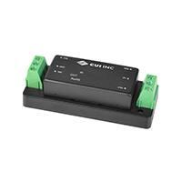


 工商网监
湘ICP备2023018690号
工商网监
湘ICP备2023018690号
