Additional Resources:
Product Page
|
3D Model
date
09/13/2021
page
1 of 8
SERIES: VFK600-DIN │ DESCRIPTION: DC-DC CONVERTER
FEATURES
•
•
•
•
•
•
•
•
•
•
up to 700 W isolated output
rugged metal enclosure with integrated heat sink
2:1 input range (18~36 Vdc, 36~75 Vdc)
single output from 12~48 Vdc
1,500 Vdc isolation
over current, over temperature, over voltage,
and short circuit protections
remote on/off
N+1 current sharing
efficiency up to 92%
comes with DIN-rail mount
MODEL
input
voltage
output
voltage
output
current
output
power
ripple
and noise1
efficiency
range
(Vdc)
(Vdc)
max
(A)
max
(W)
max
(mVp-p)
typ
(%)
VFK600-D24-S12-DIN
18 ~ 36
12
50
600
120
89
VFK600-D24-S24-DIN
18 ~ 36
24
25
600
240
91
VFK600-D24-S28-DIN
18 ~ 36
28
21.5
600
280
90
VFK600-D24-S32-DIN
18 ~ 36
32
19
608
320
91
VFK600-D24-S48-DIN
18 ~ 36
48
12.5
600
480
92
VFK600-D48-S12-DIN
36 ~ 75
12
50
600
120
90
VFK600-D48-S24-DIN
36 ~ 75
24
25
600
240
91
VFK600-D48-S28-DIN
36 ~ 75
28
25
700
280
91
VFK600-D48-S32-DIN
36 ~ 75
32
19
608
320
92
VFK600-D48-S48-DIN
36 ~ 75
48
12.5
600
480
92
Notes:
1. Ripple and noise are measured at full load, 20 MHz BW with 10µF tantalum capacitor and 1µF ceramic capacitor across output
PART NUMBER KEY
VFK600 - DXX - SXX - DIN
Base Number
Input Voltage
Output Voltage
cui.com
Mounting Type
DIN = DIN-rail mount
�Additional Resources:
Product Page
|
3D Model
CUI Inc │ SERIES: VFK600-DIN │ DESCRIPTION: DC-DC CONVERTER
date 09/13/2021 │ page 2 of 8
INPUT
parameter
conditions/description
operating input voltage
24 Vdc input models
48 Vdc input models
input current
24 Vdc input models, Vin = 18 Vdc, full load
48 Vdc input models, Vin = 36 Vdc, full load
typ
max
units
18
36
24
48
36
75
Vdc
Vdc
37.7
21.7
A
A
24 Vdc input
power up
power down
16
15
17
16
18
17
Vdc
Vdc
48 Vdc input
power up
power down
34
32
35
33
36
34
Vdc
Vdc
24 Vdc input
power up
power down
38
40
Vdc
Vdc
48 Vdc input
power up
power down
77
80
Vdc
Vdc
under voltage shutdown
over voltage shutdown
models ON (3.5~7.5 Vdc or open circuit)
CTRL1
positive logic
input fuse
60 A time delay fuse for 24 Vin models,
30 A time delay fuse for 48 Vin models
filter
pi filter
Note:
min
models OFF (0~0.7 Vdc)
1. Open collector refer to -Vin.
OUTPUT
parameter
conditions/description
min
maximum capacitive load
12 V output models
24~48 V output models
470
470
line regulation
load regulation
typ
max
units
10,000
5,000
μF
μF
measured from low line to high line
±0.2
%
measured from zero load to full load
±0.5
%
±1.5
%
voltage accuracy
load share accuracy
50~100% load
±10
adjustability
60
switching frequency
48 V input, 12/28/32 V output models
all other models
transient response
25% step load change
%
110
300
250
kHz
kHz
500
temperature coefficient
%
±0.03
µs
%/°C
PROTECTIONS
parameter
conditions/description
min
short circuit protection
continuous
over current protection
% nominal output current
110
over voltage protection
%Vo
115
over temperature protection
shutdown
typ
max
units
150
%
140
110
%
°C
SAFETY AND COMPLIANCE
parameter
conditions/description
isolation voltage
for 1 minute: input to output; input to case;
output to case
min
isolation resistance
RoHS
2011/65/EU (CE)
cui.com
typ
max
units
1,500
Vdc
10
MΩ
�Additional Resources:
Product Page
|
3D Model
CUI Inc │ SERIES: VFK600-DIN │ DESCRIPTION: DC-DC CONVERTER
date 09/13/2021 │ page 3 of 8
ENVIRONMENTAL
parameter
conditions/description
min
max
units
operating temperature
see derating curves
-40
85
°C
-55
105
°C
max
units
storage temperature
typ
MECHANICAL
parameter
conditions/description
dimensions
7.83 x 5.00 x 2.11 (199.0 x 127.0 x 53.6 mm)
min
case material
steel and aluminum extrusion
typ
inch
weight
1.53
kg
MECHANICAL DRAWING
units: mm[inch]
tolerance: X.XX = ±0.02[±0.5]
X.XXX = ±0.010[±0.25]
wire range: 22~12 AWG
screw size: #6-32
mounts to TS35 rails
0.18 4.5
PIN CONNECTIONS
FUNCTION
+Vin
5, 6
-Vin
7, 8
+Vo
9
+S
10
PC
11
Trim
12
-S
13, 14
-Vo
+Vin
REM Case
6
14
1.29 32.7
5.12 130.0
7.69 195.4
0.07 1.8
7.83 198.9
Top View
-Vin
0.57 14.6
case
1.54[39.0]
REM
4
0.50 12.8
3
7
1
4.63 117.5
5.00 127.0
PIN
1, 2
-Vo
-S -Trim Pc
+S
+Vo
1.38 35.0
2 - DIN RAIL CLIP
OUTPUT
1.57 40.0
INPUT
1.58 40.0
1.91 48.5
Back View
0.75 19.0
Side View
Front View
Bottom View
cui.com
�Additional Resources:
Product Page
CUI Inc │ SERIES: VFK600-DIN │ DESCRIPTION: DC-DC CONVERTER
|
3D Model
date 09/13/2021 │ page 4 of 8
DERATING CURVES
cui.com
�Additional Resources:
Product Page
|
3D Model
CUI Inc │ SERIES: VFK600-DIN │ DESCRIPTION: DC-DC CONVERTER
date 09/13/2021 │ page 5 of 8
TEST CONFIGURATION
Figure 1
Table 1
Recommended External components
cui.com
C1
220 μF/100 V
C2
470 μF/100 V
�Additional Resources:
Product Page
CUI Inc │ SERIES: VFK600-DIN │ DESCRIPTION: DC-DC CONVERTER
|
3D Model
date 09/13/2021 │ page 6 of 8
APPLICATION NOTES
1. Parallel Operation
The VFK600-DIN series are designed for parallel operation. When in parallel the load current can be shared equally between the two
modules by connecting their PC pins. The VFK600-DIN can be setup in two different modes to achieve parallel operation. The
stan dard parallel operation is suitable when load cannot be handled by a single unit, whereas the N+1 redundant operation is suitable
for loads when backup power is required.
STANDARD PARALLEL CONNECTION
PARALLEL CONNECTION WITH PROGRAMMED AND
ADJUSTABLE OUTPUT
N+1 REDUNDANT CONNECTION
N+1 REDUNDANT CONNECTION WITH PROGRAMMED
OUTPUT AND ADJUSTABLE OUTPUT VOLTAGE
cui.com
�Additional Resources:
Product Page
|
3D Model
CUI Inc │ SERIES: VFK600-DIN │ DESCRIPTION: DC-DC CONVERTER
date 09/13/2021 │ page 7 of 8
APPLICATION NOTES (CONTINUED)
2.
Output Voltage Trimming
Leave open if not used.
Figure 2
Trim-Up/Trim-Down Formulas
External Resistors
1.24 ×(
Vf =
7.68 +(
Rt ×33
)
Rt + 33
Rt ×33
)
Rt + 33
Vout = (Vo + VR) × Vf
Note: Rt = 6.8 KΩ
VO is the nominal output voltage
VOUT is the desired output voltage (up or down)
VR is the trim resistor in KΩ
Figure 3
Trim-Up/Trim-Down Formulas
External DC Voltage
Vout = VT × VO
Note: VT is the trim terminal voltage
VO is the nominal output voltage
VOUT is the desired output voltage (up or down)
Note:
1. All specifications measured at nominal line, full load, and 25°C unless otherwise specified.
cui.com
�Additional Resources:
Product Page
|
3D Model
CUI Inc │ SERIES: VFK600-DIN │ DESCRIPTION: DC-DC CONVERTER
date 09/13/2021 │ page 8 of 8
REVISION HISTORY
rev.
description
date
1.0
initial release
12/17/2013
1.01
changed DIN-rail mount
06/16/2014
1.02
company logo updated
02/12/2021
derating curves and circuit figures updated
09/13/2021
1.03
The revision history provided is for informational purposes only and is believed to be accurate.
Headquarters
20050 SW 112th Ave.
Tualatin, OR 97062
800.275.4899
Fax 503.612.2383
cui.com
techsupport@cui.com
CUI offers a two (2) year limited warranty. Complete warranty information is listed on our website.
CUI reserves the right to make changes to the product at any time without notice. Information provided by CUI is believed to be accurate and reliable. However, no responsibility is
assumed by CUI for its use, nor for any infringements of patents or other rights of third parties which may result from its use.
CUI products are not authorized or warranted for use as critical components in equipment that requires an extremely high level of reliability. A critical component is any component of a
life support device or system whose failure to perform can be reasonably expected to cause the failure of the life support device or system, or to affect its safety or effectiveness.
�
很抱歉,暂时无法提供与“VFK600-D24-S24-DIN”相匹配的价格&库存,您可以联系我们找货
免费人工找货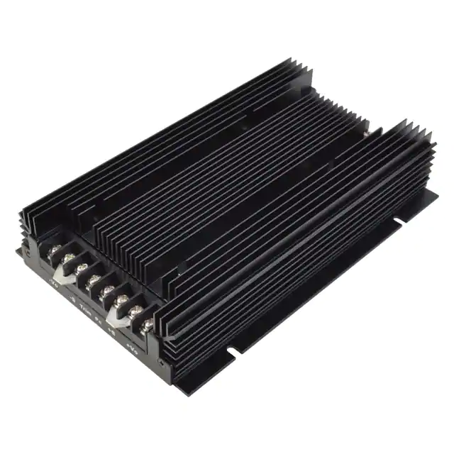


 工商网监
湘ICP备2023018690号
工商网监
湘ICP备2023018690号
