CBC-EVAL-10
EnerChip™ CC Energy Harvester Evaluation Kit
System Features and Overview
• CBC-EVAL-10 is a demonstration kit that provides designers a platform to easily develop Energy Harvesting (EH) solutions using the EnerChip CBC3150TM configured to operate in an energy harvesting mode. The kit combines a small solar panel, power management circuit, energy storage, regulated output voltage, and input/output pins for connection to commercially available microcontroller (MCU) and radio boards. A 16-pin CBC51100 module is included, providing the EH functions, battery management, and 100µAh solid state rechargeable energy storage. CBC-EVAL-10 is a practical, low cost realization of an EH-based power system that can provide many years of service without need of battery maintenance. CBC-EVAL-10 has the following elements: • Energy harvesting circuitry that matches the impedance of photovoltaic cells to ensure maximum power transfer to system load and onboard energy storage devices Solid state energy storage with thousands of charge-discharge cycles available Integrated battery management that controls battery charging and discharge cutoff, ensuring maximum service life of on-board storage cells Provision for additional energy storage (primary or rechargeable batteries) with switchover control circuit to meet application requirements Regulated output voltage with user-configurable voltage settings Input/output headers for connection to system components such as radios and microcontrollers Controls charge voltage and discharge cutoff circuit for maximizing the service life of the EnerChip solid state batteries within the CBC3150 and auxiliary CBC050 energy storage device on the CBC51100 module. Manages internal circuitry for switching from PV power to EnerChip (or external battery) power when ambient light level is too low to power the system and/or recharge the energy storage devices.
•
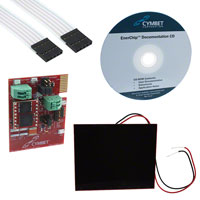
CBC-EVAL-10 is shown in Figure 1, including the 16pin CBC51100 EnerChip EH module and the PV cells attached to the board via a 2-wire cable assembly.
• •
Figure 1: CBC-EVAL-10 Demo Kit.
A block diagram of CBC-EVAL-10 is shown in Figure 2.
Photovoltaic Cells
•
• •
CBC51100 Module
Input Power Tracking Battery Management Power Management Energy Storage
The photovoltaic (PV) panel included in the CBCEVAL-10 converts ambient light energy into electrical energy, which is fed into the CBC3150 device residing on the CBC51100 module. The CBC3150 performs several important functions: • Decouples the load impedance from the PV cell impedance to ensure maximum power conversion efficiency from the PV transducer to the energy storage and system load.
External Battery and Control (Optional)
Output Voltage Regulation I/O Control
Figure 2: EnerChip CBC-EVAL-10 Demo Kit block diagram. The functions in the center block are performed by the EnerChip CBC51100 module.
DS-72-20 Rev A
©2011 Cymbet Corporation • Tel: +1-763-633-1780 • www.cymbet.com
Page 1 of 15
�CBC-EVAL-10 EnerChip CC EH Evaluation Kit
Operating Modes
CBC-EVAL-10 can be configured to operate in any of three modes, as required by the application. The operating mode is set by configuring the various jumpers on the CBC-EVAL-10. [See Figure 3 and the associated tables for jumper settings associated with each of the operating modes.] The three operating modes are as follows: 1. Standard energy harvesting mode using PV cells, on-board EnerChips, regulated output voltage, and switchover control circuit to ensure a seamless transition from PV power to EnerChips when little or no ambient light is available. In this mode, power from the PV cells is used to power the system load and charge the EnerChips when sufficient light is available. With very low or no ambient light, the system operates from on-board EnerChips. Variations of this mode are configured using jumper select pins J11, allowing the user to drive the internal charge pump of the CBC3150 through one of three control methods, as indicated on the silk screen next to J11: a) EH: External control using the BATOFF control line. Used when an external microcontroller derives input from CHARGE/ in an ‘energy-aware’ operating mode. b) CCEH: CBC3150 RESET/ output is fed to CBC3150 ENABLE input in a standard transducer impedance matching mode. c) CPEH: VIN controls the CBC3150 ENABLE line. When the input transducer voltage falls below 2.5V, the CBC3150 charge pump is disabled. 2. Energy harvesting mode that relies on not only the on-board EnerChips for energy storage, but also taps into the capacity of a conventional non-rechargeble battery when the EnerChips are at low state-of-charge, such as during extended periods of darkness. Typical batteries might be 2-series alkaline cells, primary coin cells, or certain cylindrical cells having output voltage of 3V to 3.6V. This ‘battery assist’ energy harvesting mode can be used to supplement conventional batteries, extending their operational life by months or years. 3. Energy harvesting mode that uses not only the PV cells and on-board EnerChips, but also an external rechargeable battery such as a rechargeable coin cell or other small, Li-ion or Li-polymer cells having a charging voltage of ~4.1V. This ‘extra capacity’ operating mode allows the designer to incorporate a higher capacity rechargeable battery in order to achieve longer system run-time in periods of darkness than what the EnerChips can provide, while avoiding the relative bulk associated with non-rechargeable cells. In all operating modes, the input power source - whether PV cells, EnerChips, or external battery - passes through a linear drop-out regulator (LDO) that supplies power to VOUT. The LDO output voltage is set at 2.5V but can be modified to 3.0V - through selection of J12 and J13 solder traces - or to 2.2V or 3.3V by replacing regulator U4 with regulator U6 (not populated) as indicated in the schematic of Figure 4 and Table 1: CBCEVAL-10 Bill of Materials. A power-on-reset (POR) circuit drives the LDO ENABLE pin in all operating modes except when an external non-rechargeable battery is providing power to the LDO. To avoid starving the external system elements of power particularly during start-up or when pulse currents are required by the system, the POR circuit enables the LDO only after the output capacitors are fully charged to a voltage above the LDO drop-out voltage. Consequently, the user must recognize the relationship between the POR trip voltage and the LDO turn-on voltage when designing with a POR/LDO combination other than the components installed on the CBC-EVAL-10 module.
DS-72-20 Rev A
©2011 Cymbet Corporation • Tel: +1-763-633-1780 • www.cymbet.com
Page 2 of 15
�CBC-EVAL-10 EnerChip CC EH Evaluation Kit
External Control of the CBC-EVAL-10 Energy Harvesting Functions
In addition to protecting the EnerChips from being discharged too deeply in low ambient light conditions or abnormally high current load conditions, the CBC3150 power management circuit also ensures that the system load is powered with a smooth power-on transition. The power management circuit has a control line (CHARGE/) for indication to the system controller that the energy harvester is charging the EnerChips. A control line input (BATOFF) is available for the external controller to disable the CBC3150 charge pump. Use of these two control lines is optional. There are several connectors on CBC-EVAL-10 for connection to target devices to be powered. Either the J9 or J10 connector can be used for low power microcontroller-based systems. In the case of a low power wireless end device, the CBC-EVAL-10 has storage energy for approximately 1000 radio transmissions - depending on protocol used - in no/low ambient light conditions. Microcontroller-based systems that are powered by the CBC-EVAL-10 should contain firmware that is “Energy Harvesting Aware” and take advantage of the power management status and control signals available on CBCEVAL-10.
Using Additional EnerChips and External Batteries
The CBC-EVAL-10 is designed to permit attachment of rechargeable and non-rechargeable batteries whereby the energy harvesting circuitry extends the life of those batteries by operating from (i) PV cell power when sufficient light is available, (ii) EnerChips when in an acceptable state-of-charge, and (iii) the external battery when neither of those two conditions exists. Two classes of external batteries may be attached to the CBC-EVAL-10: 1. A primary battery (i.e., non-rechargeable) or series combination of primary batteries may be connected to header pins J3 only. The acceptable voltage range is 2.7 to 3.6. Commonly used batteries in this category are: A single 3V CR-type or BR-type coin cell (e.g., CR2032, BR2032), or two alkaline cells (e.g., AAA, AA, C, D) connected in series. A single 3.6V thionyl chloride cell may also be used. Contact Cymbet for recommendations in selecting a primary battery for your application. 2. A secondary (i.e., rechargeable) battery may be connected to header pins J7 only. The acceptable charging voltage range is 4.0V to 4.2V. The charging source for this battery is the VCHG output pin of the CBC3150 that normally charges the EnerChips to 4.1V. Maximum drive current of this pin is on the order of 1mA. VCHG drive current can be adjusted by populating capacitor C9 (module shipped without a capacitor). See DS-72-03 EnerChip CC CBC3150 Data Sheet for guidelines on sizing the charge pump capacitor. The discharge cutoff voltage is fixed at 3.0V +/- 0.3V. Examples of rechargeable batteries supported by CBCEVAL-10 are the LiR-type coin cells, including LiR-1220 (~8mAh) and LiR-2032 (~40mAh). The charging rate for these external cells will be a function of available light, to a maximum of 1mA as limited by the CBC3150 charge pump drive current. To operate the CBC-EVAL-10 board for use with an external battery, configure the header pins as follows: 1. Non-rechargeable (i.e., primary) battery connected to EXT BAT terminal block J3: J1 and J2 - shorted J4, J5, J6 - not shorted J7 - no connection 2. Rechargeable (i.e., secondary) battery connected to header pins J7: J1, J2 - not shorted J3 - no connection J4, J5, and J6 - shorted
DS-72-20 Rev A
©2011 Cymbet Corporation • Tel: +1-763-633-1780 • www.cymbet.com
Page 3 of 15
�CBC-EVAL-10 EnerChip CC EH Evaluation Kit
CBC-EVAL-10 Module Connectors, Jumpers, and Test Points
TP1 J3 TP2
CONNECTORS
Connector Pin Number 1 Designation External Primary Battery Input (+) External Primary Battery Input (-) J14
J2 J6 J3
J1 J4
J5
J7
TP3 J8 CBC51100 J11 TP4
2
Connector Type: Terminal Block External Rechargeable Battery Input (+) External Rechargeable Battery Input (-)
1
1 J7 2 J10
1
J9
J15 J8 TP5 J12 J13
Connector Type: vias 1 2 PV Cell Input (+) PV Cell Input (-)
Connector Type: Terminal Block 1 2 J9 3 4 5 CHARGE/ BATOFF No Connection GND VOUT
Figure 3: Locations of connectors, jumpers, and test points.
JUMPERS
Jumper J1 J2 J4 J5 J6 J11 Pin Number 1-2 1-2 1-2 1-2 1-2 1-2 3-4 5-6 Designation External Battery to LDO Enable External Battery Mode Enable External Battery Bypass VOUT to LDO Enable Voltage Threshold Detect to LDO Enable External Control of Energy Harvesting Normal Energy Harvesting Mode Disable Energy Harvesting J10
Connector Type: Vertical SIP 1 2 3 4 5 6 BATOFF GND No Connection No Connection VOUT CHARGE/
Connector Type: Right Angle SIP
TEST POINTS
Test Point Designation External Primary Battery (+) GND DC Input (PV+) VOUT GND TP1 TP2 TP3 TP4 TP5
PCB TRACES and PADS
Reference J12 J13 J15 Designation LDO Voltage Select LDO Voltage Select Schottky Diode Bypass
DS-72-20 Rev A
©2011 Cymbet Corporation • Tel: +1-763-633-1780 • www.cymbet.com
Page 4 of 15
�CBC-EVAL-10 EnerChip CC EH Evaluation Kit
CBC-EVAL-10 Module Connector Descriptions
J3: Terminal block for connecting the positive and negative terminals of an external non-rechargeable battery.
See specifications elsewhere in this document for the minimum and maximum allowable battery voltage before attaching a battery to this connector.
J7: Header pins to be used only for the purpose of connecting the positive and negative terminals of an
external 4.1V rechargeable battery. No other connections are allowed on these pins and the pins are not to be shorted together. See specifications elsewhere in this document for the minimum and maximum allowable external battery voltage before attaching a battery to this connector.
J8: Terminal block for connecting a photovoltaic cell (or other DC voltage). See specifications elsewhere in this
document for the minimum and maximum allowable DC voltage to be applied to this connector.
J9 and J10: Power and handshaking signals for connection to a target board - e.g. wireless end-point module.
(For reference, header connector J9 is a 5-pin section of Samtec 50-pin header p/n TSW-150-07-G-S. Header connector J10 is Mill-Max p/n 850-10-006-20-001000; the socket it mates to is Mill-Max p/n 851-93-006-20001000.)
J14: Used for factory test purposes only. Do not make any connections to J14. Cable Assembly - A 5-conductor cable with a header connector at each end is provided with CBC-EVAL-10 to
facilitate connection between the J9 connector and a 5-pin header on the user’s board.
Getting Started
To operate the CBC-EVAL-10 in the standard energy harvesting mode, using the EnerChips as the storage devices, leave each of the several jumpers in the same position as received. The factory default settings are as follows: Header J1 J2 J3 J4 J5 J6 J7 J8 J9 J10 J11 J12 J13 J14 J15 Shorting Jumper, Connector, or Solder Trace/Pad No No No Yes Yes Yes No. DO NOT APPLY A SHORTING JUMPER TO J7 UNDER ANY CIRCUMSTANCES! Doing so will destroy the EnerChips. PV Cell Input (2.5VDC to 5.5VDC) System I/O (See J9 and J10 Pin Descriptions Table) System I/O (See J9 and J10 Pin Descriptions Table) Pin 3 to Pin 4 Leave as is for 2.5V Regulated Output (Cut J12 and Short J13 for 3.0V Regulation) Leave as is for 2.5V Regulated Output (Cut J12 and Short J13 for 3.0V Regulation) No Connections Necessary (Used for Factory Testing) Leave as is for 2.5V Regulated Output
DS-72-20 Rev A
©2011 Cymbet Corporation • Tel: +1-763-633-1780 • www.cymbet.com
Page 5 of 15
�CBC-EVAL-10 EnerChip CC EH Evaluation Kit
After confirming the header pins are properly configured, simply connect the 2-wire cable assembly from the PV panel to jumper J8. [Note polarity; red wire goes to the positive terminal, pin 1.] Expose the PV panel to ambient light of greater than 200 Lux. The EnerChip storage devices on the CBC51100 module will begin to charge and power will be supplied to the load via header pins J9 and J10. The magnitude of power available to the load will be a function of the ambient light, the angle of incidence of light to the PV panel, and the state of charge of the EnerChips. To verify that the circuit is operating properly, measure the voltage on any of the readily accessible test points: Test Point TP1 TP2 TP3 TP4 TP5 Node Description External Battery Terminals System Ground PV Input Regulated Output System Ground
The various header pins may also be used as test measurement points. Refer to the schematic of Figure 4. Reference the CBC3150 data sheet for operating characteristics of the CBC3150. Users may populate R2 and R3 to set the maximum power point of the DC transducer. See the CBC3150 data sheet for recommended resistor values. Note that the resistor divider will present a parasitic load to the transducer.
DS-72-20 Rev A
©2011 Cymbet Corporation • Tel: +1-763-633-1780 • www.cymbet.com
Page 6 of 15
�CBC-EVAL-10 EnerChip CC EH Evaluation Kit
Connecting CBC-EVAL-10 to the System
The CBC-EVAL-10 board has two control lines that can be connected to a microcontroller (MCU) for the purpose of conserving available energy, using incoming power efficiently, and extending EnerChip battery life. The table below describes the functionality of the J9 and J10 connector pins. J9 and J10 Pin Descriptions Pin
BATOFF
Designation
Input control line to the CBC-EVAL-10 for disconnecting the EnerChips from the CBC-EVAL-10 charging circuit. See the section System Design Recommendations to Save Power for additional information. Active low output from the CBC-EVAL-10 indicating that the EnerChips have been charged or are being charged (provided CBC3150 EN pin was/ is high). CHARGE/ is an open drain output with an internal 1.0MΩ pull-up resistor to VOUT. See the section System Design Recommendations to Save Power for additional information. CBC-EVAL-10 output power System ground No connection (J9 has one NC pin and J10 has two NC pins)
CHARGE/
VOUT GND NC
• BATOFF is typically controlled by a microcontroller I/O line. When driven high, the CBC3150 charge pump will be disabled. This feature allows all available power to be delivered to the load rather than to charging the EnerChips, a useful mode when limited transducer power is available or when higher operating current is required from the system. When BATOFF is driven low, the interaction between the charging source and the CBC-EVAL-10 behaves normally. In other words, when BATOFF is low the EnerChips will always be charging when sufficient input power is available. • CHARGE/ is an output signal from the CBC-EVAL-10. CHARGE/ is a logical inversion of the CBC3150 RESET/ output signal. Therefore, CHARGE/ will be driven low (RESET/ driven high) whenever VIN is at a voltage above the VMODE switchover setpoint (nominally 3.0V with VMODE tied to GND). In CCEH mode - as configured by jumper J11 - RESET/ is tied to EN, meaning the charge pump will be active and the batteries will be charging only when RESET/ is high. During operating conditions when RESET/ is toggling on and off at some duty cycle (for example in low light), CHARGE/ will also be toggling. To determine whether the batteries are charged during such conditions, an MCU could be programmed to integrate the total time that CHARGE/ is low over some elapsed time or pre-defined use period. From that data, it can be inferred whether the batteries are charged and available for use in the event input power (VIN) drops below the level required to operate the charge pump at all. • VOUT is the DC output voltage from the CBC-EVAL-10 and is typically 2.5V, depending on system configuration and load current. It provides power to the system according to the Operating Characteristics table shown below. • GND is the ground connection of the CBC-EVAL-10. It is to be connected to the system ground line.
DS-72-20 Rev A
©2011 Cymbet Corporation • Tel: +1-763-633-1780 • www.cymbet.com
Page 7 of 15
�CBC-EVAL-10 EnerChip CC EH Evaluation Kit
Operating Characteristics (1)
Parameter
Input Luminous Intensity (using PV cells provided with kit) Photovoltaic Input Voltage (VIN) External Battery Voltage
Condition
Minimum operating Lux Full charge rate 25°C Non-rechargeable Rechargeable 1000 Lux (FL); battery not charging; continuous output 200 Lux (FL), battery not charging No ambient light, EnerChips charged
Min
250 (2) 800 2.7 4.0 2.48 3.0 0 5000 1000 2500 500 100
(2)
Typical
3.2 (3) 3.0 4.1 300 10 2000 (4) 2.5 3.3 30 (5) 2.5 25 10 50 -
Max
5.5 3.6 4.2 2.52 3.6 70 -
Units
Lux Lux Volts DC Volts DC Volts DC µA µA µA V V mA % per year °C minutes minutes µAh
Continuous Output Power (measured at VOUT pin; 25°C)
VOUT
EnerChip and External Rechargeable Battery Discharge Cutoff Voltage Pulse Discharge Current EnerChip Self-Discharge (non-recoverable) Operating Temperature EnerChip Recharge Cycles (to 80% of rated capacity; 4.1 V charge voltage) 25°C 40°C
Battery charged; 2µA load 4.7kΩ load 25°C ; 20 msec pulse 5-year average 25°C 10% depth-of-discharge 50% depth-of discharge 10% depth-of-discharge 50% depth-of-discharge From 50% state-of-charge
EnerChip Recharge Time (to 80% of rated capacity) From deep discharge EnerChip Storage Capacity 200 µA discharge; 25°C
(1) See DS-72-03 EnerChip CC CBC3150 Data Sheet and DS-72-01 EnerChip CBC050 Data Sheet for complete specifications of the Cymbet components on the CBC51100 module included with CBC-EVAL-10. (2) Fluorescent (FL) light conditions. EnerChip state-of-charge >90%. (3) Dependent on battery state-of-charge and load conditions. State-of-charge will affect average VIN. At 0% battery stateof-charge, 2.6V < VIN < 3.1V, depending on load. At 100% battery state-of-charge, VIN will approach 5.2V at 700Lux. (4) Continuous current for up to 1 minute with CBC51100 EnerChip module. (5) For guidelines on adjusting the pulse current capability, see AN-1025: Using the EnerChip in Pulse Current Applications.
Specifications subject to change without notice.
CBC-EVAL-10 Circuit Schematics
As a result of designing the CBC-EVAL-10 to be versatile and useful for designing to any number of operating environments and system requirements, there are many circuit elements that will not be necessary for any given CCEH implementation. The full schematic of Figure 4 depicts the CBC-EVAL-10 in its entirety. A simpler and more often used embodiment is shown in Figure 5. In Figure 5, the provision for external batteries has been removed, as has the circuitry required for external system control of the CBC3150 charge pump. The schematic of Figure 5 is reduced to the essential elements necessary for implementing an energy harvestingbased design using the CBC3150 circuitry and EnerChip batteries. ©2011 Cymbet Corporation • Tel: +1-763-633-1780 • www.cymbet.com
DS-72-20 Rev A
Page 8 of 15
�CBC-EVAL-10 EnerChip CC EH Evaluation Kit
CBC-EVAL-10 Circuit Schematic
Figure 4: CBC-EVAL-10 Circuit Schematic.
DS-72-20 Rev A
©2011 Cymbet Corporation • Tel: +1-763-633-1780 • www.cymbet.com
Page 9 of 15
�Figure 5: CBC-EVAL-10 Circuit Schematic with External Battery and External System Control Circuits Removed.
DS-72-20 Rev A
©2011 Cymbet Corporation • Tel: +1-763-633-1780 • www.cymbet.com
Page 10 of 15
�CBC-EVAL-10 EnerChip CC EH Evaluation Kit
CBC-EVAL-10 Assembly Diagram
Figure 6: CBC-EVAL-10 Assembly Diagram (Top View). Table 1: CBC-EVAL-10 Bill of Materials.
DS-72-20 Rev A
©2011 Cymbet Corporation • Tel: +1-763-633-1780 • www.cymbet.com
Page 11 of 15
�CBC-EVAL-10 EnerChip CC EH Evaluation Kit
Using Other Energy Harvesting Transducers
CBC-EVAL-10 includes a standard amorphous silicon solar panel (Sanyo AM1815 type) configured as 8 seriesconnected cells on a glass substrate. The output voltage and current vary with incident light intensity, wavelength, and load impedance. DC sources other than the PV cell provided with the CBC-EVAL-10 may also be used as the energy harvesting power transducer. While the CBC-EVAL-10 module has a Zener diode at the transducer input to limit high voltage excursions at 5.6V, it is recommended that any DC transducer input be limited to 5.5V under all anticipated operating conditions. The minimum input voltage required to activate the internal charge pump of the CBC3150 is 2.5V. At


 工商网监
湘ICP备2023018690号
工商网监
湘ICP备2023018690号
