P6KE SERIES
TRANSIENT VOLTAGE
SUPPRESSOR
VBR : 6.8 - 600 Volts
PPK : 600 Watts
DO-15
FEATURES :
1.00 (25.4)
MIN.
0.142 (3.6)
0.102 (2.6)
*
*
*
*
*
Glass passivated jungtion chip
600W surge capability at 1ms
Excellent clamping capability
Low zener impedance
Fast response time : typically less
then 1.0 ps from 0 volt to VBR(min.)
* Typical IR less then 1mA above 10V
0.300 (7.6)
0.230 (5.8)
1.00 (25.4)
MIN.
0.034 (0.86)
0.028 (0.71)
* Moisture Sensitivity Level 1 (Unlimited)
* Pb / RoHS Free
MECHANICAL DATA :
Dimensions in inches and ( millimeters )
* Case : DO-15 Molded plastic
* Epoxy : UL94V-0 rate flame retardant
* Lead : Axial lead solderable per MIL-STD-202,
Method 208 guaranteed
* Polarity : Color band denotes cathode end
* Mounting position : Any
* Weight : 0.4 gram
DEVICES FOR BIPOLAR APPLICATIONS
For Bi-directional use C or CA Suffix
Electrical characteristics apply in both directions
MAXIMUM RATINGS
Rating at 25 C ambient temperature unless otherwise specified.
Rating
Peak Power Dissipation at Ta = 25 °C, Tp=1ms (Note1)
Steady State Power Dissipation at TL = 75 C
Symbol
Value
Unit
PPK
Minimum 600
W
PD
5.0
W
TJ, TSTG
- 65 to + 175
°C
Lead Lengths 0.375", (9.5mm) (Note 2)
Operating and Storage Temperature Range
Notes :
(1) Non-repetitive Current pulse, per Fig. 5 and derated above Ta = 25 C per Fig. 1
(2) Mounted on Copper Leaf area of 1.57 in2 (40mm2).
Page 1 of 4
Rev. 09 : December, 2017
�ELECTRICAL CHARACTERISTICS
Breakdown Voltage @ It
( Note 1 )
Min.
Max.
It
(mA)
Working Peak
Reverse
Voltage
VRWM
(V)
6.12
6.45
6.75
7.13
7.38
7.79
7.65
8.08
8.19
8.65
9.00
9.50
9.90
10.5
10.8
11.4
11.7
12.4
13.5
14.3
14.4
15.2
16.2
17.1
18.0
19.0
19.8
20.9
21.6
22.8
24.3
25.7
25.2
26.6
27.0
28.5
29.7
31.4
32.4
34.2
35.1
37.1
38.7
40.9
42.3
44.7
45.9
48.5
50.4
53.2
55.8
58.9
61.2
64.6
7.48
7.14
8.25
7.88
9.02
8.61
9.35
8.93
10.0
9.55
11.0
10.5
12.1
11.6
13.2
12.6
14.3
13.7
16.5
15.8
17.6
16.8
19.8
18.9
22.0
21.0
24.2
23.1
26.4
25.2
29.7
28.4
30.8
29.4
33.0
31.5
36.3
34.7
39.6
37.8
42.9
41.0
47.3
45.2
51.7
49.4
56.1
53.6
61.6
58.8
68.2
65.1
74.8
71.4
10
10
10
10
10
10
10
10
1.0
1.0
1.0
1.0
1.0
1.0
1.0
1.0
1.0
1.0
1.0
1.0
1.0
1.0
1.0
1.0
1.0
1.0
1.0
1.0
1.0
1.0
1.0
1.0
1.0
1.0
1.0
1.0
1.0
1.0
1.0
1.0
1.0
1.0
1.0
1.0
1.0
1.0
1.0
1.0
1.0
1.0
1.0
1.0
1.0
1.0
5.50
5.80
6.05
6.40
6.63
7.02
6.89
7.27
7.37
7.78
8.10
8.55
8.92
9.40
9.72
10.2
10.5
11.1
12.1
12.8
12.9
13.6
14.5
15.3
16.2
17.1
17.8
18.8
19.4
20.5
21.8
23.1
22.7
23.9
24.3
25.6
26.8
28.2
29.1
30.8
31.6
33.3
34.8
36.8
38.1
40.2
41.3
43.6
45.4
47.8
50.2
53.0
55.1
58.1
Type No.
VBR (V)
P6KE6.8
P6KE6.8A
P6KE7.5
P6KE7.5A
P6KE8.2
P6KE8.2A
P6KE8.5
P6KE8.5A
P6KE9.1
P6KE9.1A
P6KE10
P6KE10A
P6KE11
P6KE11A
P6KE12
P6KE12A
P6KE13
P6KE13A
P6KE15
P6KE15A
P6KE16
P6KE16A
P6KE18
P6KE18A
P6KE20
P6KE20A
P6KE22
P6KE22A
P6KE24
P6KE24A
P6KE27
P6KE27A
P6KE28
P6KE28A
P6KE30
P6KE30A
P6KE33
P6KE33A
P6KE36
P6KE36A
P6KE39
P6KE39A
P6KE43
P6KE43A
P6KE47
P6KE47A
P6KE51
P6KE51A
P6KE56
P6KE56A
P6KE62
P6KE62A
P6KE68
P6KE68A
Page 2 of 4
( Rating at 25 °C ambient temperature unless otherwise specified.)
Maximum
Reverse Leakage
@ VRWM
IR
(mA)
Maximum
Reverse
Current
IRSM
(A)
Maximum
Clamping
Voltage @ IRSM
VRSM
(V)
Maximum
Temperature
Co-efficient
of VBR
1000
1000
500
500
200
200
200
200
150
150
150
150
150
150
5.0
5.0
5.0
5.0
5.0
5.0
5.0
5.0
5.0
5.0
5.0
5.0
5.0
5.0
5.0
5.0
5.0
5.0
5.0
5.0
5.0
5.0
5.0
5.0
5.0
5.0
5.0
5.0
5.0
5.0
5.0
5.0
5.0
5.0
5.0
5.0
5.0
5.0
5.0
5.0
55.5
57.0
51.0
53.0
48.0
50.0
46.0
47.0
44.0
45.0
40.0
41.0
37.0
38.0
35.0
36.0
32.0
33.0
27.0
28.0
26.0
27.0
23.0
24.0
21.0
22.0
19.0
20.0
17.0
18.0
15.0
16.0
15.0
15.5
14.0
14.4
12.6
13.2
11.6
12.0
10.6
11.2
9.6
10.1
8.9
9.3
8.2
8.6
7.4
7.8
6.8
7.1
6.1
6.5
10.8
10.5
11.7
11.3
12.5
12.1
13.0
12.7
13.8
13.4
15.0
14.5
16.2
15.6
17.3
16.7
19.0
18.2
22.0
21.2
23.5
22.5
26.5
25.2
29.1
27.7
31.9
30.6
34.7
33.2
39.1
37.5
40
38.7
43.5
41.4
47.7
45.7
52.0
49.9
56.4
53.9
61.9
59.3
67.8
64.8
73.5
70.1
80.5
77.0
89.0
85.0
98.0
92.0
0.057
0.057
0.061
0.061
0.065
0.065
0.067
0.067
0.068
0.068
0.073
0.073
0.075
0.075
0.078
0.078
0.081
0.081
0.084
0.084
0.086
0.086
0.088
0.088
0.090
0.090
0.092
0.092
0.094
0.094
0.096
0.096
0.096
0.096
0.097
0.097
0.098
0.098
0.099
0.099
0.100
0.100
0.101
0.101
0.101
0.101
0.102
0.102
0.103
0.103
0.104
0.104
0.104
0.104
(% / C)
Rev. 09 : December, 2017
�ELECTRICAL CHARACTERISTICS
Breakdown Voltage @ It
( Note 1 )
Type No.
VBR (V)
Min.
Max.
It
(mA)
( Rating at 25 °C ambient temperature unless otherwise specified.)
Working Peak
Reverse
Voltage
VRWM
(V)
Maximum
Reverse Leakage
@ VRWM
IR
(mA)
P6KE75
67.5
82.5
1.0
60.7
5.0
P6KE75A
71.3
78.8
1.0
64.1
5.0
P6KE82
73.8
90.2
1.0
66.4
5.0
P6KE82A
77.9
86.1
1.0
70.1
5.0
P6KE91
81.9
100.0
1.0
73.7
5.0
P6KE91A
86.5
95.5
1.0
77.8
5.0
P6KE100
90.0
110.0
1.0
81.0
5.0
P6KE100A
95.0
105.0
1.0
85.5
5.0
P6KE110
99.0
121.0
1.0
89.2
5.0
P6KE110A
105.0
116.0
1.0
94.0
5.0
P6KE120
108.0
132.0
1.0
97.2
5.0
P6KE120A
114.0
126.0
1.0
102
5.0
P6KE130
117.0
143.0
1.0
106
5.0
P6KE130A
124.0
137.0
1.0
111
5.0
P6KE150
135.0
165.0
1.0
121
5.0
P6KE150A
143.0
158.0
1.0
128
5.0
P6KE160
144.0
176.0
1.0
130
5.0
P6KE160A
152.0
168.0
1.0
136
5.0
P6KE170
153.0
187.0
1.0
138
5.0
P6KE170A
162.0
179.0
1.0
145
5.0
P6KE180
162.0
198.0
1.0
146
5.0
P6KE180A
171.0
189.0
1.0
154
5.0
P6KE200
180.0
220.0
1.0
162
5.0
P6KE200A
190.0
210.0
1.0
171
5.0
P6KE220
198.0
242.0
1.0
175
5.0
P6KE220A
209.0
231.0
1.0
185
5.0
P6KE250
225.0
275.0
1.0
202
5.0
P6KE250A
237.0
263.0
1.0
214
5.0
P6KE300
270.0
330.0
1.0
243
5.0
P6KE300A
285.0
315.0
1.0
256
5.0
P6KE320
288.0
352.0
1.0
259
5.0
P6KE320A
303.0
337.0
1.0
272
5.0
P6KE350
315.0
385.0
1.0
284
5.0
P6KE350A
332.0
368.0
1.0
300
5.0
P6KE400
360.0
440.0
1.0
324
5.0
P6KE400A
380.0
420.0
1.0
342
5.0
P6KE440
396.0
484.0
1.0
356
5.0
P6KE440A
418.0
462.0
1.0
376
5.0
P6KE480
432.0
528.0
1.0
389
5.0
P6KE480A
456.0
504.0
1.0
408
5.0
P6KE510
459.0
561.0
1.0
413
5.0
P6KE510A
485.0
535.0
1.0
434
5.0
P6KE530
477.0
583.0
1.0
457
5.0
P6KE530A
503.5
556.5
1.0
477
5.0
P6KE540
486.0
594.0
1.0
437
5.0
P6KE540A
513.0
567.0
1.0
459
5.0
P6KE550
495.0
605.0
1.0
470
5.0
P6KE550A
522.5
577.5
1.0
495
5.0
P6KE600
540.0
660.0
1.0
490
5.0
P6KE600A
570.0
630.0
1.0
512
5.0
Notes : ( 1 ) VBR measured after It applied for 300 ms., It = square wave pulse or equivalent.
( 2 ) For Bipolar types moving VR of 10 Volts and under, the IR limit is doubled.
( 3 ) "6KE" will be omitted in marking on the diode.
Page 3 of 4
Maximum
Reverse
Current
IRSM
(A)
Maximum
Clamping
Voltage @ IRSM
VRSM
(V)
Maximum
Temperature
Co-efficient
of VBR
5.5
5.8
5.1
5.3
4.5
4.8
4.2
4.4
3.8
4.0
3.5
3.6
3.2
3.3
2.8
2.9
2.6
2.7
2.5
2.6
2.3
2.4
2.1
2.2
1.75
1.83
1.67
1.75
1.40
1.45
1.31
1.35
1.20
1.25
1.05
1.10
0.95
1.00
0.88
0.90
0.82
0.86
0.76
0.80
0.78
0.81
0.76
0.80
0.71
0.75
108
103
118
113
131
125
144
137
158
152
173
165
187
179
215
207
230
219
244
234
258
246
287
274
344
328
360
344
430
414
460
445
504
482
574
548
631
602
686
658
729
698
798
725
772
740
836
760
911
828
0.105
0.105
0.105
0.105
0.106
0.106
0.106
0.106
0.107
0.107
0.107
0.107
0.107
0.107
0.108
0.108
0.108
0.108
0.108
0.108
0.108
0.108
0.108
0.108
0.108
0.108
0.110
0.110
0.110
0.110
0.110
0.110
0.110
0.110
0.110
0.110
0.110
0.110
0.110
0.110
0.110
0.110
0.110
0.110
0.110
0.110
0.110
0.110
0.110
0.110
(% / C)
Rev. 09 : December, 2017
�RATING AND CHARACTERISTIC CURVES ( P6KE SERIES )
FIG. 2 - TYPICAL JUNCTION CAPACITANCE
UNI-DIRECTIONAL
120
CJ, JUNCTION CAPACITANCE (pF)
PEAK PULSE DERATING IN % OF
PEAK POWER OR CURRENT
FIG.1 - PULSE DERATING CURVE
100
80
60
40
20
0
0
25
50
75
100
125
150
10000
Measured at
Zero Bias
1000
TJ = 25C
f = 1.0 MHz
Vsig = 50mVp-p
Measured at
Stand-off
Voltage, VWM
100
10
175
1
Ta, AMBIENT TEMPERATURE, ( C)
FIG.3 - STEADY STATE POWER DERATING
100
200
FIG.4 - PULSE RATING CURVE
10
Pp,PEAK POWER (kW)
5.00
PD, STEADY STATE POWER
DISSIPATION (W)
10
V(BR), Breakdown Voltage (V)
3.75
2.50
1.25
Single Phase Half Wave
60 Hz Resistive or Inductive load
10
1.0
0.1
0.1ms
1.0ms
10ms
100ms
1.0ms
10ms
0
0
25
50
75
100
125
150
175
200
tp, PULSE WIDTH
TL, LEAD TEMPERATURE (°C)
PEAK PULSE CURRENT - % IRMS
FIG.5 - PULSE WAVEFORM
Tr = 10ms
100
Peak Value
IRMS
TJ=25 °C
Pulse Width (tp) is defined
as that point where the peak
current decays to 50%
of IRSM
Half Value - IRMS
2
50
10X1000 Waveform
tp
0
0
1.0
2.0
3.0
4.0
T, TIME(ms)
Page 4 of 4
Rev. 09 : December, 2017
�
很抱歉,暂时无法提供与“P6KE82A”相匹配的价格&库存,您可以联系我们找货
免费人工找货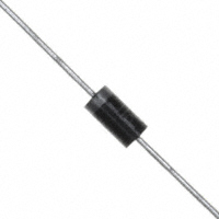


 工商网监
湘ICP备2023018690号
工商网监
湘ICP备2023018690号
