H-Bridge Kit 2Go - Board User Manual
H-Bridge Kit 2Go
Evaluation Board for DC Motor Control with the IFX9201
About this document
Scope and purpose
This board user manual provides a basic introduction to the hardware of the H-Bridge Kit 2Go.
The H-Bridge Kit 2Go is a complete low cost system solution for driving small brushed DC motors. It contains a
32bit microcontroller including debug interface, an on board 5 V voltage regulator, reverse polarity protection
for the power supply and an integrated H-Bridge capable of driving up to 6 A peak, the IFX9201SG.
Intended audience
This board user manual is intended for anyone interested in evaluating DC motor control with the IFX9201.
Board User Manual
www.infineon.com
Please read the Important Notice and Warnings at the end of this document
Revision 1.3
2016-10-19
�H-Bridge Kit 2Go
Evaluation Board for DC Motor Control with the IFX9201
Table of Contents
Table of Contents
About this document ............................................................................................................................................. 1
Table of Contents .................................................................................................................................................. 2
1
Overview ............................................................................................................................................ 3
2
2.1
2.2
2.3
2.4
2.5
Getting Started................................................................................................................................... 4
Power Supply........................................................................................................................................... 4
Selecting a DC motor............................................................................................................................... 4
Connecting the Kit ................................................................................................................................... 4
Software................................................................................................................................................... 5
Port Assignment ...................................................................................................................................... 5
3
3.1
3.2
3.3
Demo operation ................................................................................................................................. 6
Device discovery ...................................................................................................................................... 6
Firmware update using DAVE™ ............................................................................................................... 6
Operation via Terminal interface............................................................................................................ 9
4
4.1
4.2
Hardware Description ...................................................................................................................... 13
Schematics ............................................................................................................................................ 13
Layout .................................................................................................................................................... 17
Board User Manual
2
Revision 1.3
2016-10-19
�H-Bridge Kit 2Go
Evaluation Board for DC Motor Control with the IFX9201
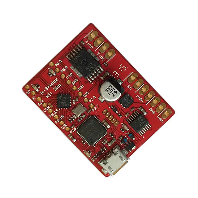
Overview
1
Overview
The H-Bridge Kit 2Go is based on the Infineon microcontroller kit XMC 2Go. For any information on the XMC 2Go
as well as for downloading the software drivers and tools please visit http://www.infineon.com/xmc2go.
H-Bridge
IFX9201
Supply Cap
XMC 2Go
Reverse
Polarity
Protection
5V
Regulator
Micro
USB
Figure 1
Top View H-Bridge Kit 2Go
Figure 2
Block Diagram H-Bridge Kit 2Go
Board User Manual
3
Revision 1.3
2016-10-19
�H-Bridge Kit 2Go
Evaluation Board for DC Motor Control with the IFX9201
Getting Started
2
Getting Started
2.1
Power Supply
For providing the power to drive a DC motor the H-Bridge Kit 2Go needs an external power supply connected to
VBAT. To protect the board from accidentialy reverted supply voltages the H-Bridge Kit 2Go is equipped with a
reverse polarity protection circuit.
As with the XMC 2Go the microcontroller can be supplied by the PC via the Micro USB port. To enable
standalone operation without a connection to the PC the H-Bridge Kit 2Go also features an on board 5 V voltage
regulator which acts a pre-regulator for the 3.3 V regulator of the microcontroller.
Attention: The 5 V regulator is a linear voltage regulator and can get very hot depending on the input voltage!
VBAT can range from 5 V to a maximum of 36 V without damaging the board. However, since the power
dissipation of the 5 V regulator strongly increases with the input voltage it is recommended to keep VBAT below
15 V or to provide additional cooling by attaching a heat sink to the back side of the board.
Another option when applying a higher VBAT is to provide 5 V externally at the V5V input of the board. This will
relieve the on board regulator and enable operation up to 36 V, the maximum supply voltage of the IFX9201.
2.2
Selecting a DC motor
The IFX9201 can drive small DC motors with peak currents of up to 6 A. The achievable continuous drive current
is lower and depends on supply voltage, switching frequency and the cooling conditions. Realistic continuous
drive currents for this kit are in the range of 1 A to 2 A. Many motors for toys, RC models or robotics fall in this
range.
2.3
Connecting the Kit
To get started with the Kit just connect a suitable DC Motor and the power supply as shown in Figure 3.
The power pads are spaced with a 2.54 mm pitch. Each power signal (except V5V) is occupying two pads.
Therefore it is possible to use either 2.54 mm or 5.08 mm spaced connectors or screw terminals.
Figure 3
Connecting Motor, Supply and USB Cable
Board User Manual
4
Revision 1.3
2016-10-19
�H-Bridge Kit 2Go
Evaluation Board for DC Motor Control with the IFX9201
Getting Started
2.4
Software
The kit comes pre-programmed with a simple example routine that applies a 1 kHz PWM signal to the motor
and ramps the speed of the motor up and down by increasing and decreasing the PWM duty cycle. When
reaching a duty cycle of 0% it reverts the rotation direction of the motor and starts again with ramping the
motor speed up and down.
There is demo code available which can be downloaded at http://www.infineon.com/h-bridge-kit-2go. See
chapter 3 for more details. This program was generated using the Infineon code development platform DAVE™
(Version 4). For information on this tool, how to use it and for downloading please visit
http://www.infineon.com/dave.
2.5
Port Assignment
When writing your own routines for driving the IFX9201 please refer to the IFX9201 data sheet and the following
port assignment of XMC microcontroller ports (see Table 1).
Table 1
XMC1100 Port Assignment to IFX9201 signals
Port
IFX9201 signal
Comment
P0.6
SO
SPI serial output
P0.7
SI
SPI serial input
P0.8
SCK
SPI clock input
P0.9
CSN
SPI chip select (low active)
P2.0
DIR
Direction input to define direction of the motor current
P2.10
PWM
Pulse width modulation input
P2.11
DIS
Disable. Disables the outputs (all MOSFETS off)
Board User Manual
5
Revision 1.3
2016-10-19
�H-Bridge Kit 2Go
Evaluation Board for DC Motor Control with the IFX9201
Demo operation
3
Demo operation
As mentioned in section 2.4, there is software available for download at http://www.infineon.com/h-bridge-kit2go. It has extended functionality to control the H-Bridge Kit 2Go with a PC using the Terminal interface. This
chapter describes the firmware update process using DAVE™, the setup of the terminal program and the
available commands.
3.1
Device discovery
Make sure the J-Link driver is installed properly. This is included in the installation of DAVE™ (see
http://www.infineon.com/dave). For more details on J-Link please visit www.segger.com.
Then connect the H-Bridge Kit 2Go to the USB port of your PC. The driver for the H-Bridge Kit 2Go will now be
installed (this may require administrator priviledges). Check in the “Device Manager” that the “JLink CDC UART
Port” has been installed correctly; it should look like Figure 4 (the number of the COM Port may be different).
Figure 4
3.2
Correct installation of JLink UART Port
Firmware update using DAVE™
After download and extraction of the firmware example, do the following in DAVE™:
In DAVE™, go to “File” – “Import”. Then select “Infineon” – “DAVE project” and click “Next”. See Figure 5 for
details.
Board User Manual
6
Revision 1.3
2016-10-19
�H-Bridge Kit 2Go
Evaluation Board for DC Motor Control with the IFX9201
Demo operation
Figure 5
Import project
Select the folder with the extracted demo project and click on “Finish”. Keep “Copy Projects Into Workspace”
checked (see Figure 6).
Figure 6
Import project (2)
Now the demo project will be imported. The screen should look like in Figure 7.
Board User Manual
7
Revision 1.3
2016-10-19
�H-Bridge Kit 2Go
Evaluation Board for DC Motor Control with the IFX9201
Demo operation
Figure 7
DAVE Screen after import of demo project
Now connect the H-Bridge Kit 2Go to a USB port (unless already done). You should see one of the red LEDs go
on and off (5s on, 5s off, …). Click on “Generate Code” and “Build Active Project”. Then click on the “Debug”
button. The following screen will appear (see Figure 8).
Board User Manual
8
Revision 1.3
2016-10-19
�H-Bridge Kit 2Go
Evaluation Board for DC Motor Control with the IFX9201
Demo operation
Figure 8
Debug Configuration
Again, click on “Debug”. There may be a recommendation to update the J-Link interface. If you decide to go for
the update, you will need to click “Debug” again after the update is complete. Then the new demo firmware is
installed on the board.
3.3
Operation via Terminal interface
Open the Terminal software. Select the serial interface and “JLINK CDC UART Port”. See Figure 9.
Board User Manual
9
Revision 1.3
2016-10-19
�H-Bridge Kit 2Go
Evaluation Board for DC Motor Control with the IFX9201
Demo operation
Figure 9
Select “JLINK CDC UART Port”
The port now needs to be configured according to Figure 10.
Figure 10
Set up Serial Port
After completing the above steps, type in “?” to make sure communication is working. A command overview as
shown in Figure 11 or Table 2 is displayed.
Board User Manual
10
Revision 1.3
2016-10-19
�H-Bridge Kit 2Go
Evaluation Board for DC Motor Control with the IFX9201
Demo operation
Figure 11
Command overview, displayed when “?” is entered
Board User Manual
11
Revision 1.3
2016-10-19
�H-Bridge Kit 2Go
Evaluation Board for DC Motor Control with the IFX9201
Demo operation
Table 2
H-Bridge Kit 2Go command list standard operation mode
Command
Argument 1
Argument 2
Example
Description
?
-
-
‘?’
Show available commands
help
-
-
‘help’
Show available commands
dis
0/1
-
‘dis 1’ / ‘dis 0’
Set DIS pin high or low
d
-
-
‘d’
Enable = ‘dis 1’
e
-
-
‘e’
Enable = ‘dis 0’
dir
0/1
-
‘dir 1’ / ‘dir 0’
Set DIR pin high or low
f
-
-
‘f’
Forward = ‘dir 1’
r
-
-
‘r’
Reverse = ‘dir 0’
pwm
Duty cycle [%]
Frequency [Hz]
‘pwm 50 1000’
Set PWM duty cycle and frequency
p
Duty cycle [%]
Frequency [Hz]
‘p 50’
Frequency is optional (default 1 kHz)
spi
Hex value
-
‘spi 2A’
Write to spi; expects 2 digit hex value
s
Hex value
-
‘s 2a’
Lower case or capital
dia
-
-
‘dia’
Show diagnosis register
res
-
-
‘res’
Reset diagnosis register
rev
-
-
‘rev’
Show revision register
ctrl
-
-
‘ctrl’
Show control register
oldis
0/1
-
‘oldis 1’
Disconnect open load current source
sin
0/1
-
‘sin 1’ / sin 0’
Set control via SPI on or off
sen
0/1
-
‘sen 1’ / ‘sen 0’
Set EN via SPI high or low
sdir
0/1
-
‘sdir 1’ / ‘sdir 0’
Set DIR via SPI high or low
spwm
0/1
-
‘spwm 1’ / ‘spwm 0’ Set PWM via SPI high or low
This interface provides a simple method to control the H-Bridge to a PC.
Note: If there is no connection via USB, the device will still operate as explained in section 2.4.
Board User Manual
12
Revision 1.3
2016-10-19
�H-Bridge Kit 2Go
Evaluation Board for DC Motor Control with the IFX9201
Hardware Description
4
Hardware Description
4.1
Schematics
Figure 12
Power Connectors
Figure 13
Reverse Polarity Protection
Board User Manual
13
Revision 1.3
2016-10-19
�H-Bridge Kit 2Go
Evaluation Board for DC Motor Control with the IFX9201
Hardware Description
Figure 14
5 V Regulator
Figure 15
IFX9201 and Peripherals
Board User Manual
14
Revision 1.3
2016-10-19
�H-Bridge Kit 2Go
Evaluation Board for DC Motor Control with the IFX9201
Hardware Description
Figure 16
XMC1100 and Pin Header
Board User Manual
15
Revision 1.3
2016-10-19
�H-Bridge Kit 2Go
Evaluation Board for DC Motor Control with the IFX9201
Hardware Description
Figure 17
3.3 V Regulator and User LEDs
Figure 18
On Board Debugger including UART to USB Bridge
Board User Manual
16
Revision 1.3
2016-10-19
�H-Bridge Kit 2Go
Evaluation Board for DC Motor Control with the IFX9201
Hardware Description
4.2
Layout
Figure 19
Component Placement
Figure 20
Top Layer
Board User Manual
17
Revision 1.3
2016-10-19
�H-Bridge Kit 2Go
Evaluation Board for DC Motor Control with the IFX9201
Hardware Description
Figure 21
Bottom Layer
Board User Manual
18
Revision 1.3
2016-10-19
�Trademarks of Infineon Technologies AG
AURIX™, C166™, CanPAK™, CIPOS™, CoolGaN™, CoolMOS™, CoolSET™, CoolSiC™, CORECONTROL™, CROSSAVE™, DAVE™, DI-POL™, DrBlade™, EasyPIM™,
EconoBRIDGE™, EconoDUAL™, EconoPACK™, EconoPIM™, EiceDRIVER™, eupec™, FCOS™, HITFET™, HybridPACK™, Infineon™, ISOFACE™, IsoPACK™,
i-Wafer™, MIPAQ™, ModSTACK™, my-d™, NovalithIC™, OmniTune™, OPTIGA™, OptiMOS™, ORIGA™, POWERCODE™, PRIMARION™, PrimePACK™,
PrimeSTACK™, PROFET™, PRO-SIL™, RASIC™, REAL3™, ReverSave™, SatRIC™, SIEGET™, SIPMOS™, SmartLEWIS™, SOLID FLASH™, SPOC™, TEMPFET™,
thinQ!™, TRENCHSTOP™, TriCore™.
Trademarks updated August 2015
Other Trademarks
All referenced product or service names and trademarks are the property of their respective owners.
Edition 2016-10-19
Published by
Infineon Technologies AG
81726 Munich, Germany
ifx1owners.
©
2016 Infineon Technologies AG.
All Rights Reserved.
Do you have a question about this
document?
Email: erratum@infineon.com
Document reference
H-Bridge Kit 2Go - Board User Manual
IMPORTANT NOTICE
The information contained in this application note
is given as a hint for the implementation of the
product only and shall in no event be regarded as a
description or warranty of a certain functionality,
condition or quality of the product. Before
implementation of the product, the recipient of this
application note must verify any function and other
technical information given herein in the real
application.
Infineon
Technologies
hereby
disclaims any and all warranties and liabilities of
any kind (including without limitation warranties of
non-infringement of intellectual property rights of
any third party) with respect to any and all
information given in this application note.
The data contained in this document is exclusively
intended for technically trained staff. It is the
responsibility of customer’s technical departments
to evaluate the suitability of the product for the
intended application and the completeness of the
product information given in this document with
respect to such application.
For further information on the product, technology,
delivery terms and conditions and prices please
contact your nearest Infineon Technologies office
(www.infineon.com).
WARNINGS
Due to technical requirements products may
contain dangerous substances. For information on
the types in question please contact your nearest
Infineon Technologies office.
Except as otherwise explicitly approved by Infineon
Technologies in a written document signed by
authorized
representatives
of
Infineon
Technologies, Infineon Technologies’ products may
not be used in any applications where a failure of
the product or any consequences of the use thereof
can reasonably be expected to result in personal
injury.
�


 工商网监
湘ICP备2023018690号
工商网监
湘ICP备2023018690号
